KADİR HAS UNIVERSITY
GRADUATE SCHOOL OF SCIENCE AND ENGINEERING PROGRAM OF PhD IN ELECTRONICS ENGINEERING
SPARSE CHANNEL ESTIMATION AND DATA
DETECTION ALGORITHMS FOR OFDM-BASED
UNDERWATER ACOUSTIC COMMUNICATION
SYSTEMS
Mhd Tahssin ALTABBAA
DOCTOR of PHILOSOPHY THESIS
Mhd Ta hssi n AL TA B B AA P h.D. T he sis 2018 S tudent’ s F ull Na me P h.D. (or M.S . or M.A .) The sis 20 11
SPARSE CHANNEL ESTIMATION AND DATA
DETECTION ALGORITHMS FOR OFDM-BASED
UNDERWATER ACOUSTIC COMMUNICATION
SYSTEMS
Mhd Tahssin ALTABBAA
DOCTOR of PHILOSOPHY THESIS
Submitted to the Graduate School of Science and Engineering of Kadir Has University in partial fulfillment of the requirements for the degree of Doctorate’s in the Program of
Electronics Engineering
DECLARATION OF RESEARCH ETHICS / METHODS OF DISSEMINATION
I, Mhd Tahssin ALTABBAA, hereby declare that;
this Doctorate’s Thesis is my own original work and that due references have been appropriately provided on all supporting literature and resources;
this Doctorate’s Thesis contains no material that has been submitted or accepted for a degree or diploma in any other educational institution;
I have followed “Kadir Has University Academic Ethics Principles” prepared in accordance with the “The Council of Higher Education’s Ethical Conduct Principles” In addition, I understand that any false claim in respect of this work will result in disciplinary action in accordance with University regulations.
Furthermore, both printed and electronic copies of my work will be kept in Kadir Has Information Center under the following condition as indicated below:
The full content of my thesis/project will be accessible from everywhere by all means.
Mhd Tahssin ALTABBAA
__________________________
KADIR HAS UNIVERSITY
GRADUATE SCHOOL OF SCIENCE AND ENGINEERING
ACCEPTANCE AND APPROVAL
This work entitled SPARSE CHANNEL ESTIMATION AND DATA DETECTION ALGORITHMS FOR OFDM-BASED UNDERWATER ACOUSTIC
COMMUNICATION SYSTEMS prepared by Mhd Tahssin ALTABBAA has been judged to be successful at the defense exam held on 09/11/2018 and accepted by our jury as DOCTORATE’S THESIS.
TABLE OF CONTENTS
TABLE OF CONTENTS ... 7 ABSTRACT ... i ÖZET ... iii ACKNOWLEDGMENTS ... v LIST OF TABLES ... viLIST OF FIGURES ... vii
LIST OF ABBREVIATIONS ... ix
1. INTRODUCTION ... 1
1.1 Motivation ... 1
1.2 State-of-the-art on Channel Estimation Algorithms ... 1
1.3 Contribution of This Work ... 5
2. STATE-OF-THE-ART ON UNDERWATER ACOUSTIC COMMUNICATIONS ... 7
2.1 History of Underwater Acoustical Communications ... 7
2.2 Why Acoustic Signals ... 7
2.3 Characteristics of Underwater Acoustic Channel ... 8
2.3.1 Sound Velocity ... 9
2.3.2 Propagation Loss ... 9
2.3.2.1 Absorptive Loss ... 10
2.3.2.2 Scattering Loss ... 11
2.3.3 Ambient Noise and Interference ... 12
2.3.4 Large Doppler Shift ... 14
2.3.5 Long propagation Delay ... 15
2.3.6 Multipath Propagation and Channel Models ... 15
2.4 Bellhop Acoustic Toolbox ... 18
2.4.1 Overview ... 18
2.4.2 Environmental Profile ... 19
3. SPARSE CHANNEL ESTIMATION AND DATA DETECTION FOR
OFDM-BASED UNDERWATER ACOUSTIC SYSTEMS IN RICIAN FADING ... 21
3.1 Introduction ... 21
3.2 System and Channel Model ... 22
3.3 Sparse Multipath Channel Estimation ... 29
3.3.1 Preprocessing ... 29
3.3.2 Path Delays and Doppler Spread Estimation ... 30
3.3.3 Path Gains Estimation 𝒉𝓵 ... 31
3.3.4 ML Estimation of the Prior Unknown Mean and Variance 𝝁𝓵, 𝒔𝓵𝓵𝑳 − 𝟏 34 3.4 Equalization and data Detection ... 37
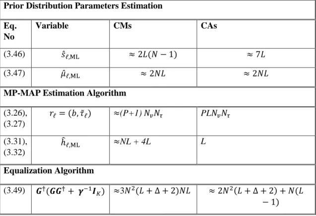
3.5 Computation Complexity ... 38
3.6 Computer Simulations with BELLHOP Simulated Channels in Sapanca Lake ... 40
3.7 OMP-MAP Estimation ... 48
3.7.1 OMP-MAP Algorithm ... 49
3.7.2 Simulation Results for UWA Channel undergoing Rician Fading with different non-uniform Doppler rates ... 51
3.7.3 Simulation Results for UWA Channel undergoing log-normal and Nakagami-m Fading with different non-uniform Doppler rates ... 56
3.7.4 Conclusion ... 60
4. SPARSE CHANNEL ESTIMATION FOR SPACE-TIME BLOCK CODED OFDM-BASED UNDERWATER ACOUSTIC CHANNELS ... 61
4.1 Introduction ... 61
4.2 Alamouti’s Transmit Diversity Scheme For OFDM Systems ... 63
4.3 Representation of The Discrete UWA Channel ... 64
4.4 EM-Based Map Sparse Channel Estimation ... 66
4.4.1 initialization ... 68
4.4.2 Computation of 𝚪𝝁𝒒 for QPSK Signalling ... 70
4.4.3 Final Sparse Channel Estimation ... 70
4.5 Simulation Results ... 72
4.6 Conclusion ... 76
i
SPARSE CHANNEL ESTIMATION AND DATA DETECTION ALGORITHMS FOR OFDM-BASED UNDERWATER ACOUSTIC COMMUNICATION SYSTEMS
ABSTRACT
Communication over acoustic signals in underwater results into a scale multi-lag channels, which occurs due to the multipath propagation. Hence, a robust channel estimation technique has to be present at the receiver, and the solutions of the terrestrial-based systems are not applicable. In this work, using path-based channel model that characterizes underwater channels by a delay, a Doppler shift, and an attenuation factors, three new pilot assisted, time domain-based channel estimation algorithms are proposed for single-input single-output communication-based and diversity communication-communication-based underwater acoustic systems. The multicarrier transmission technique assumed is OFDM. In addition, depending on the base stations deployment in underwater, the sparse underwater channels undergo Rician or Rayleigh fading, where channels in this work are generated using Bellhop software. In the first two proposed approach, the overall sparse channel tap delays and constant Doppler shifts are estimated using Matching Pursuit and Orthogonal Matching Pursuit algorithms, where the sparse complex channel path gain vector is estimated by maximum a posteriori probability (MAP) technique, and the prior densities of the channel gains follow Rician distribution with unknown mean and variance vectors, where Maximum Likelihood is proposed for their estimation. The first approach considers a colored noise and uniform Doppler spread, and the second approach considers a non-uniform Doppler shifts with white noise. The third proposed approach considers transmitter diversity with Alamouti’s coding, where the channel estimator iteratively estimates the complex channel parameters of each subcarrier using the expectation maximization method, which in turn converges to a true maximum a posteriori probability estimation of the unknown channel, where Karhunen-Loeve expansion and ESPRIT algorithm are assumed for complexity reduction and delay estimation, respectively. Finally, in
ii
order to assess the performance of the proposed algorithms, the computer simulations show the behavior in terms of mean square error and symbol error rate.
Keywords: Channel estimation, detection, equalization, underwater acoustic communication, Alamouti coding, space-time coding, expectation maximization algorithm, maximum a posteriori channel estimation.
iii
DFBÇ TABANLI SUALTI AKUSTİK HABERLEŞME SİSTEMLERİ İÇİN SEYREK KANAL KESTİRİMİ VE VERİ TESPİT ALGORİTMALARI
ÖZET
Sualtındaki akustik sinyallerle haberleşme çokyollu yayılımdan dolayı çok ölçekli çok gecikmeli kanallara yol açmaktadır. Bu nedenle, kara tabanlı çözümler uygulanamamakta ve alıcı tarafında kuvvetli kanal kestirim teknikleri sunulmalıdır. Bu çalışmada, tek girişli tek çıkışlı haberleşme tabanlı ve çeşitli haberleşme tabanlı sualtı akustik sistemleri için sualtı kannallarını gecikme, Doppler kayması ve sönümleme unsuru ile karakterize eden yol tabanlı kanal modeli kullanılarak iki yeni kılavuz yardımcılı, zaman bölgesi tabanlı kanal kestirim algoritmaları önerilmiştir. Çok-taşıyıcılı verici tekniği olarak dikey frekans bölmeli çoklama (DFBÇ) kabul edilmiştir. Ek olarak, baz istasyonlarının konuşlanmalarına bağlı olarak, seyrek sualtı kanalları Rician veya Rayleigh sönümlemesine uğramaktadır ve her ikisi de bu çalışmada göz önünde bulundurulmuştur ve Bellhop yazılımı bunların üretimi için kullanılmıştır. İlk önerilen yaklaşımda, seyrek karmaşık kanal yol kazanç vektörünün maksimum sonsal olasılık (MSO) tekniğiyle kestirildiği durumda, kanal kazancının öncelikli yoğunluğunun bilinmeyen ortalama gradiyent ve varyans vektörlerine sahip Rician dağılımı takip ettiği ve bunların kestirimi için enbüyük olabilirlik (EO) tekniğinin önerildiği durumda genel seyrek kanal çıkma gecikmeleri ve sabit Doppler kaymaları Matching Pursuit (MP) algoritması kullanılarak kestirilmiştir. İlk yaklaşıma bir genişletme yapılmış, algoritmada düzensiz Doppler kayması değerlendirilmiş ve Orthogonal Matching Pursuit (OMP) kullanışmıştır. İkinci önerilen yaklaşımda ise Alamouti kodlamasıyla verici çeşitliliği değerlendirilmiş, kanal kestirici tekrarlı olarak her bir alt taşıyıcının karmaşık kanal parametrelerini beklenti maksimizasyonu (BM) metoduyla kestirmekte olup, bilinmeyen kanalın kestirimi doğru maksimum sonsal olasılık (MSO) kestirimine yakınsamış, ve karmaşıklık azaltmak ve gecikme hesabı için sırasıyla Karhunen-Loeve genişletmesi
iv
ve ESPRIT algoritması kabul edilmiştir. Son olarak, önerilmiş algoritmanın performansını değerlendirmek için bilgisayar benzetimleriyle sistem davranışı ortalama karesel hata (OKH) ve işaret hata oranı (İHO) cinsinden gösterilmiştir.
Anahtar Sözcükler: Kanal kestirimi, belirleme, eşitleme, sualtı akustik haberleşme, Alamouti kodlama, uzay-zaman kodlama, beklenti maksimizasyonu algoritması, maksimum sonsal olasılık kestirimi
v
ACKNOWLEDGMENTS
Praises and thankfulness to Allah, the most merciful and most compassionate for the great bounties bestowed upon me and granting me the strength to seek knowledge. A PhD thesis is a singularly authored document, but not one that is written in isolation. I would like to start with expressing my sincere gratitude to my thesis advisor Prof. Dr. Erdal PANAYIRCI for his beneficial advices, incessant encouragement, enduring patience, and constant support. I am indebted to Prof. PANAYIRCI for providing me with clear explanations and always giving me his time. It was a great honor for me to serve as a teaching and research assistant during my doctorate studies at Kadir Has University. However, I would like to show my appreciation to the members of the school of science and engineering faculty, notably, my admiration for Assoc. Prof. Serhat ERKÜÇÜK and Assoc. Prof. Metin ŞENGÜL for their encouragements along my PhD studies. In addition, I would like to thank Asst. Prof. Atilla ÖZMEN and Asst. Prof. Selçuk ÖĞRENCİ for their kindness and friendliness when I was attending their courses as an assistant in the lab. I would like to thank Asst. Prof. Bahattin KARAKAYA from Istanbul University, for his guidance and help in setting up Bellhop software. I also would like to show my appreciation to my colleagues at Kadir Has University and say “good luck to all of you. Working with you guys was an advantageous for me and full of fun”. Last but not the least, I would like to show my appreciation to my family, my mother, my sisters and their lovely families.
This work would not have been possible without support from the Suasis as a sub-contract of the Turkish Scientific and Research Council (TUBITAK) under Grant 1140029, and in part by the U.S. National Science Foundation under Grant CCF-1420575, and in part by KAUST under grant No. OSR-2016-CRG 5-2958-02.
vi
LIST OF TABLES
Table 2.1Comparison of acoustic, EM and optical waves in underwater medium ... 8 Table 3.1Computational complexity details ... 39 Table 3.2 Channel and simulation parameters for Sapanca Lake ... 44
vii
LIST OF FIGURES
Figure 2.1 Illustration of the overall AQUO methodology. ... 13
Figure 2.2 Short-range propagation. ... 16
Figure 2.3 Long-range propagation... 16
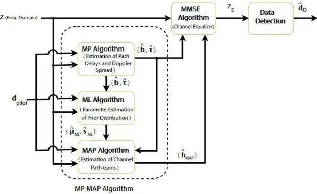
Figure 3.1 Block diagram of the MP-MAP channel estimation and equalization algorithm. ... 38
Figure 3.2 Source and destination stations in Sapanca Lake ... 40
Figure 3.3 Ray tracing for a range of 5km ... 41
Figure 3.4 Sound speed profile for Sapanca Lake ... 42
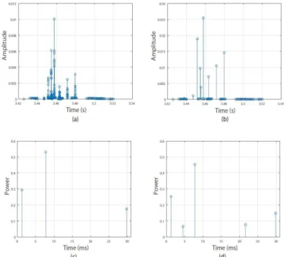
Figure 3.5 CIR for a range of 5km. (a) Original CIR with 607 paths; (b) Clustered paths with 79 clusters; (c) L = 3, delay spread = 28.5383 ms (normalized); (d) L = 5, delay spread = 28.5383 ms (normalized). ... 43
Figure 3.6 MSE vs. SNR performance comparisons of the MP-MAP and MP algorithms for different constellations: 𝜚 = 8, 𝑏𝑚𝑎𝑥 = 10 − 3, 𝛥𝑝 = 4. ... 45
Figure 3.7 SER vs. SNR performance comparisons of the MP-MAP and MP algorithms for different constellations: 𝜚 = 8, 𝑏𝑚𝑎𝑥 = 10 − 3, 𝛥𝑝 = 4. ... 45
Figure 3.8 MSE vs. SNR performance of the MP-MAP algorithm for different resolution factors: 𝑏𝑚𝑎𝑥 = 10 − 3, 𝛥𝑝 = 4, 16QAM signaling. ... 46
Figure 3.9 SER vs. SNR performance of the MP-MAP algorithm for different resolution factors: 𝑏𝑚𝑎𝑥 = 10 − 3, 𝛥𝑝 = 4,16QAM signaling. ... 46
Figure 3.10 MSE vs. SNR performance of the MP-MAP algorithm for different Doppler rates: 𝜚 = 8, 𝛥𝑝 = 4, 16QAM signaling. ... 47
Figure 3.11 SER vs. SNR performance of the MP-MAP algorithm for different Doppler rates: 𝜚 = 8, 𝛥𝑝 = 4, 16QAM signaling. ... 47
Figure 3.12 MSE vs. SNR performance of the MP-MAP algorithm for different pilot spacings: 𝜚 = 16, 𝑏𝑚𝑎𝑥 = 10 − 3, 16QAM signaling. ... 48
Figure 3.13 SER vs. SNR performance of the MP-MAP algorithm for different pilot spacings: 𝜚 = 16, 𝑏𝑚𝑎𝑥 = 10 − 3, 16QAM signaling. ... 48
Figure 3.14 Block diagram of the OMP-MAP channel estimation and equalization algorithm ... 49
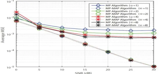
Figure 3.15 MSE vs. SNR performance comparisons of the OMP-MAP and OMP algorithms for different constellations: 𝜚 = 4, 𝑏𝑚𝑎𝑥 = 10 − 4, 𝛥𝑝 = 4. ... 51
Figure 3.16 SER vs. SNR performance comparisons of the OMP-MAP and OMP algorithms for different constellations: 𝜚 = 4, 𝑏𝑚𝑎𝑥 = 10 − 4, 𝛥𝑝 = 4. ... 52
Figure 3.17 MSE vs. SNR performances of the OMP-MAP and OMP algorithms for different resolution factors: 𝑏𝑚𝑎𝑥 = 10 − 3, 𝛥𝑝 = 4,16QAM signaling. ... 53
Figure 3.18 SER vs. SNR performances of the OMP-MAP and OMP algorithms for different resolution factors: 𝑏𝑚𝑎𝑥 = 10 − 3, 𝛥𝑝 = 4,16QAM signaling. ... 53
Figure 3.19 MSE vs. Doppler rate performances of the OMP-MAP and OMP algorithms for different Doppler rates: 𝜚 = 8, 𝛥𝑝 = 4, 16QAM signaling. ... 54
Figure 3.20 SER vs. Doppler rate performances of the OMP-MAP and OMP algorithms for different Doppler rates: 𝜚 = 8, 𝛥𝑝 = 4, 16QAM signaling. ... 54
Figure 3.21 SER vs. SNR performance of the OMP-MAP algorithm for different pilot spacings: 𝜚 = 4, 𝑏𝑚𝑎𝑥 = 10 − 4, 16QAM signaling. ... 55
Figure 3.22 MSE vs. SNR performances of the OMP-MAP, OMP and FISTA algorithms with QPSK signaling, 𝜚 = 4, 𝑏𝑚𝑎𝑥 = 10 − 4, 𝛥𝑝 = 4. ... 56
viii
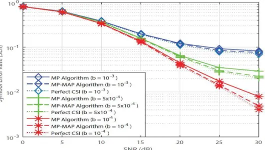
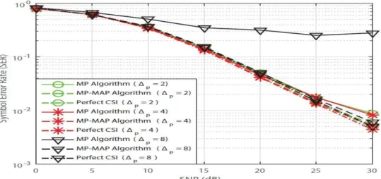
Figure 3.23 SER vs. SNR performances of the OMP-MAP, OMP and FISTA algorithms with QPSK signaling, 𝜚 = 4, 𝑏𝑚𝑎𝑥 = 10 − 4, 𝛥𝑝 = 4. ... 56 Figure 3.24 MSE vs. SNR comparisons of the OMP-MAP and OMP algorithms for different fading models with QPSK signaling, 𝜚 = 4, 𝑏𝑚𝑎𝑥 = 10 − 4, 𝛥𝑝 = 4 (random case channel). ... 59 Figure 3.25 SER vs. SNR comparisons of the OMP-MAP and OMP algorithms for different fading models with QPSK signaling, 𝜚 = 4, 𝑏𝑚𝑎𝑥 = 10 − 4, 𝛥𝑝 = 4 (random case channel). ... 59 Figure 4.1 MSE vs. SNR performance of the MAP-EM-ESPRIT algorithm for different residual Doppler rates b= [ 10 − 3, 5 × 10 − 3, 10 − 3] with 𝛥𝑠𝑐= 4. ... 73 Figure 4.2 SER vs. SNR performance of the MAP-EM-ESPRIT algorithm for different residual Doppler rates b= [ 10 − 3, 5 × 10 − 3, 10 − 3] with 𝛥𝑠𝑐= 4. ... 74 Figure 4.3 MSE vs. SNR performance of the MAP-EM-ESPRIT algorithm for different pilot spacings 𝛥𝑠𝑐= [2, 4, 8], with b = 10 − 3Hz. ... 75 Figure 4.4 SER vs. SNR performance of the MAP-EM-ESPRIT algorithm for different pilot spacings 𝛥𝑠𝑐= [2, 4, 8], with b = 10 − 3Hz. ... 75
ix
LIST OF ABBREVIATIONS
Acronym Definition
AOA Angle of Arrival
A/D Analog-to-Digital
BER Bit Error Rate
BP Basic Pursuit
CE Channel Estimation
CFO Carrier Frequency Offset
CIR Channel Impulse Response
CP Cyclic Prefix
CSI Channel State Information
CAs Complex Additions
CMs Complex Multiplications
DFT Direct Fourier Transform
EM Electromagnetic
ESPRIT Estimation of Signal Parameters via Rotational Invariance Techniques
FFT Fast Fourier Transform
FISTA Fast Iterative Shrinkage-Thresholding Algorithm
ICI Intercarrier Interference
ISI Intersymbol Interference
IDFT Inverse Direct Fourier Transform
IFFT Inverse Fast Fourier Transform
ISI Intersymbol Interference
LMMSE Linear Minimum Mean Square Error
LMS Least-Mean-Squares
LR Linear Regression
LS Least-Squares
LOS Line of Sight
MAP Maximum a posteriori
MIMO Multiple Input Multiple Output
MISO Multiple Input Single Output
ML Maximum Likelihood
MP Matching Pursuit
x
OFDM Orthogonal Frequency Division Multiplexing
OMP Othrogonal Matching Pursuit
PDF Probability Density Function
PSK Phase-Shift Keying
QAM Quadrature Amplitude Modulation
QPSK Quadrature Phase Shift-Keying
RF Radiofrequency
RLS Recursive Least-Squares
SAGE Space Alternating Generalized Expectation-maximization
SER Symbol Error Rate
SFBC Space-Frequency Block Coded
SISO Single Input Single Output
SNR Signal to Noise Ratio
SSP Sound Speed Profile
SPM Statistical Prediction Model
SVD Singular Value Decomposition
UASP Underwater Acoustic Signal processing
UHF Ultra High Frequency
UWAC Underwater Acoustic Communications
1
1. INTRODUCTION
1.1 Motivation
The surface of the earth planet is covered by more than two thirds of water including oceans, seas, rivers and lakes, where the need of having a robust communication system in the underwater environment is essential. Various applications for several domains that operate in aquatic environments require a wireless communication link for reporting and data exchange. Research laboratories and governments tend to develop this type of wireless communication in order to meet different applications such as submarine communication, seismic (tsunami) detectors, offshore oil field exploration and monitoring, intrusion detection for tactical surveillance (port and border security), maritime archaeology, data collection, environmental (pollution) monitoring and various of military applications that even wireless sensor networks found their way to such environment (Liu et al., 2008) (Chen et al., 2014.) (Zhang, et al., 2014) (Bernard and Meinig, 2011) (Mandalapa et al., 2016). The channel estimator design at the receiver side is a challenging problem in underwater due to the impairments that the signals face in such medium, which the overall system performance depends on it. The performance of an acoustical communication system in underwater depends on estimating different parameters regarding the communication channel, where the characteristics of the channel in this medium affect the channel impulse response.
1.2 State-of-the-art on Channel Estimation Algorithms
Different approaches are well-studied for a robust channel estimation. Space-time coding and multi-input multi-output (MIMO) configurations as well as orthogonal frequency division multiplexing (OFDM)-based communication systems, which were originally introduced in the context of terrestrial radiofrequency (RF) wireless communication, have been successfully applied to underwater communications in recent studies (Pelekanakis
2
and Baggeroer, 2011) (Li, et al., 2009). These techniques seem to be primary candidates for next generation UWA systems, due to their high information capacity and robustness to large multipath spreads (Tu, et al., 2011) (Emre et al., 2008) and bring significant improvements in both throughput rate and error rate performance. On the other hand, when the deployment of multi transmit/receive elements is not possible due to space or power limitations and pathloss becomes a performance limiting factor, relay-assisted (cooperative) communication has also been applied to UWA systems to take advantage of diversity benefits. These works have been mostly focused on capacity and power allocation (Choudhuri and Mitra, 2009) for UWA relay channels with intersymbol interference (ISI), distributed channel coding and space time corporative schemes for UWA channels (Vajapeyam et al., 2008) (Jalil and Ghrayeb, 2014), and on channel estimation and equalization for amplify-and-forward cooperative relay based OFDM systems in UWA channels (Panayirci et al., 2016). Notably, in (Panayirci et al., 2016), Rayleigh fading channels between source, relay and destination, an efficient algorithm is developed based on the space-alternating generalized expectation-maximization (SAGE) technique for the latter purpose.
The fundamental performance bounds of such systems are determined by the inherent characteristics of the underwater channel and by reliable channel state information (CSI) available at the destination, to enable high transmission speeds and high link reliability. However, almost all the existing works assume perfect channel estimation, which is a critical task in the receiver design, and is extremely challenging in the UWA communication context due to the large number of unknowns as a result of large delay and Doppler spread. A work on channel estimation of doubly selective UWA channels based on the use of a basis expansion model first, to reflect the time-varying nature of the channel (Qu and Yang, 2008) (Leus and Van Walree, 2008) through which some subspace algorithms, namely root-MUSIC and ESPRIT, can be applied for channel estimation (Van Trees, 2002) (Pesavento, et al., 2000).
Inspired from array processing, a subspace method can be applied to determine the distinct path arrivals, after which the complex path gains can be estimated based on pilot subcarriers. However, it has been shown that these techniques work well only for channels that have limited Doppler-spread. Also, the number of the unknowns that need to be estimated increases substantially depend on the time varying nature of the UWA channel,
3
imposing substantial demands on the channel estimation (Qu and Yang, 2008) (Leus and Van Walree, 2008). Channels with mild or more severe Doppler distortion require dedicated intercarrier interference (ICI) equalization (e.g., (Li, et al., 2008) and (Huang et al., 2011)) and channel estimation is typically accomplished using pilots only (Li at al., 2008), (Huang et al., 2011), (Stojanovic, 2008), or decision feedback instead or in addition to pilots (Li et al., 2009), (Radosevic et al., 2011).
The channel estimation algorithms described in the recent literature have been mainly based on exploiting the sparse nature of UWA channels (Li and Preisig, 2007), (Stojanovic, 2008). Given sufficiently wide transmission bandwidth, the impulse response of the underwater acoustic channel is often sparse as the multipath arrivals become resolvable (Stojanovic, 2009). Also, in the presence of large Doppler spread, channel estimation algorithms have been recently shown to be highly effective, based on experimental results for both single-carrier (Cotter and Rao, 2002) and multi-carrier (Berger et al., 2010), underwater transmissions. In these works, orthogonal matching pursuit (OMP) and other basis pursuit (BP) variants have been tested and based on the simulation and experimental studies, it was shown that BP has better performance than OMP in the UWA environment.
A channel estimation for relay-based UWA systems is investigated in (Panayirci et al., 2016). The authors considered a sparse CIR and a non-Gaussian channel gains in their channel model. The expectation-maximization (EM) along with the matching pursuit (MP) algorithms were employed for the Doppler shift and the delay estimation. In (Ma et al., 2017), the authors adopted superposition coding with OFDM for downlink communication in the presence of multiple stations (sensors).
Based on statistical representation of each underwater station’s channel state information (CSI), a resource allocation mechanism is proposed that obtains the transmitting power of each subcarrier for each user. An adaptive channel estimator based on least squares (LS) and recursive least-squares (RLS) is proposed in (Shi and yang, 2016). The results show a promising bit error rate (BER) performance and the average mean square error (MSE) can be obtained better than the linear minimum mean square error (LMMSE) or the LS. The authors of (Kumar and Sarvgaya, 2016) investigated different modulation, channel estimation, and channel equalization techniques for OFDM-based and pilot-assisted UWA systems. They assumed in their simulations a channel that follows a
4
Rayleigh distribution. Their results show that QPSK, DPSK, and 16QAM are the most suitable modulation schemes for UWA applications. The authors of (Yu et al., 2015) proposed a low computational complexity channel estimation algorithm based on fast block-Fourier transform (FFT) and orthogonal matching pursuit (OMP) in the presence of large pilot spacing. In (Peng et al., 2015), the authors proposed an OMP-based algorithm for channel coefficients estimation with no prior CSI knowledge in the presence of doubly selective channel. Two different Doppler estimation techniques are discussed in (Ahmed, 2015) for pilot-assisted OFDM-based UWAC systems. The first technique consider a cross correlation operation performed on the observed signal with the local known OFDM symbol, then the peak location(s), after that, the authors compare each peak location with the corresponding known peak location, where the difference determines the Doppler scale. The other technique is very close to the first one; mainly, after determining the peak using the local signal, an auto correlation operation is performed on the successive data OFDM symbol to determine the peak location(s). The authors compare the peak location with the reference of the corresponding peak location, where the difference in peak location pairs defines the Doppler shift (𝛾̂). In both approaches, however, a sampling operation is performed in the time domain on the observed signal in order to compensate the dominant Doppler shift, i.e. 𝑡
1+ 𝛾̂.
The noise generated in acoustic type of communication in underwater has also received efforts, due to the fact of its high power. In such environment, the main resource of noise is not only the activities of the ships, and other man-made sources, shrimps, rainfall, and wind contribute in noise generation. Authors of (Jenserud and Ivansson, 2015) proposed a study that shows a better channel impulse response modeling when out-of-plane scattering and reverberation are taken into account, whereas the authors of (Kuai et al., 2016) proposed an algorithm where the receiver can detect the impulsive noise positions using the signal amplitude in the time domain, and the impulsive noise and the Doppler shift estimation are based on the null subcarriers of the OFDM symbol.
In (Chen et al., 2017), the authors consider impulsive noise in the underwater region due to the generated by snapping shrimps and other sources noise sources, where an impulsive noise mitigation operation is carried out on the received signal. Basically, the authors consider the non-zero channel coefficients at the pilots, where the impulsive noise is detected by calculating the average power of the current OFDM block, then collects the
5
positions of possible impulsive noise into a vector that are greater than a predefined power threshold, then the algorithm subtracts the estimated impulsive noise from the received signals. Another channel estimation approach was discussed in (Liu, et al., 2016). The authors consider the non-zero paths in their channel estimation (CE) procedure, where an inverse direct Fourier transform (IDFT) operation is performed and then the algorithm selects the paths with high powers, then convert it back to the frequency domain through direct Fourier transform (DFT) operation, then the signal is equalized.
The reminder of this work is organized as follows. Chapter 2, investigates the state of the art of the underwater acoustic communications, the underwater channel characteristics, and an introduction to Bellhop acoustical toolbox. Chapter 3, discusses the proposed channel estimator along with the proposed channel and system models. In addition, chapter 3 proposes an extension to the proposed model with detailed formula derivations and simulation results with comparisons. Chapter 4, discusses the proposed channel estimation algorithm proposed for a multiple-input-single-output type of communication. Finally, chapter 5 contains concluding remarks.
1.3 Contribution of This Work
In this work, a synthetic type of channel impulse response (CIR) generated using Bellhop MATLAB-wrapper acoustic toolbox is proposed for the channel estimation problem considering the characteristic of underwater region of Sapanca Lake in Turkey. However, the proposed channel estimators are computational friendly. In the first approach, a SISO type of communication is proposed with correlated colored Gaussian noise to be added to the received signal in order to simulate a real underwater environment, where the second approach assumes a MISO type of communication with white noise, which also fits in underwater environments. In addition, the first approach assumes Rician fading channel, whereas the second algorithm assumes Rayleigh fading.
The main difference of the work in chapter 3 and (Panayirci et al., 2016) is that, this work is concerned with a synthetic type of channel based on a real environment obtained from Sapanca Lake in Turkey using the BELLHOP-MATLAB acoustic toolbox (Porter, last accessed, 2018), whereas the work in (Panayirci et al., 2016) assumes an exponentially decaying type of channel. In addition, the channels proposed in chapter 3 assumes Rician fading, whereas the channels in (Panayirci et al., 2016) undergo Rayleigh fading.
6
Moreover, in this work of chapter 3, maximum a posteriori (MAP) is proposed for channel gains estimation with maximum likelihood (ML) for the prior densities estimation, whereas in (Panayirci et al., 2016) Expectation Maximization (EM) algorithm was employed. Finally, the work in (Panayirci et al., 2016) investigates a system model with cooperative-based system, while in this work in chapter 3 the system model deals with direct communication.
The main difference of the work in chapter 4 and (Cirpan, Panayirci, & Dogan, 2006) is that this work assumes space-time type of diversity, whereas the work in (Cirpan et al., 2006) assumes a space-frequency one. In addition, the work in chapter 4 uses a sparse underwater channel generated by BELLHOP-MATLAB acoustic toolbox for Sapanca Lake in Turkey, where the work in (Cirpan et al., 2006) uses an exponentially decaying channel. Finally, the work in chapter 4 is extended by using ESPRIT algorithm for sparse channel delay estimation and a comparison of it is shown with the work discussed in (Cirpan et al., 2006).
7
2. STATE-OF-THE-ART ON UNDERWATER ACOUSTIC
COMMUNICATIONS
In this chapter, the main characteristics of underwater acoustic communication will be discussed. The objective of this chapter is to provide an insightful knowledge on the challenges and impairments that acoustic signals face in underwater environment.
2.1 History of Underwater Acoustical Communications
In 400 BC, Aristotle had noted that sound could be heard in underwater medium as well as in the air. In 15th century, Leonardo da Vinci observed the wireless communication can be made over acoustical signals in underwater environment, where his words were “If you cause your ship to stop, and place the head of a long tube in the water and place the outer extremity to your ear, you will hear sips at a great distance from you” (Vaccaro, 1998). Due to the development of electronic devices, the use of underwater acoustics has been made through hydrophones, where the latter converts the acoustic energy into electrical signal (and vice versa). Since then, several articles were made on underwater acoustic signal processing (UASP) considering solutions of multipath spread, rapid channel fluctuations, significant ambient noise, and channel estimation.
2.2 Why Acoustic Signals
Many contributions regarding wireless communications in underwater environment are well studied to enhance the performance of the overall wireless-based communication system. In order to fulfill a wireless communication link in underwater environment; there exist three candidate type of signal waves (electromagnetic, optical, and acoustic) proposed to achieve this task, where the acoustic signals are found to be the most suitable. Electromagnetic (EM) waves have been deployed in wireless communication for over a
8
century achieving a superior performance in terrestrial wireless communications offering a robust wireless link with a decent speed of propagation that provides an insignificant delay for real-time applications. Unfortunately, the radio waves were found to experience high attenuation for underwater wireless communications because of the conductive nature of the underwater medium, where a higher transmission power has to be used in order to solve this problem (Zhou and Wang, 2014).
Lately, the trend of communication over visible light has received a lot of interest among researchers, and numerous number of well-written papers are proposed for communication over this type of signals. Regrettably, due to the nature underwater medium, the optical signals scatters, and the optical powers can be absorbed rapidly (Webster et al., 2017).
Fortunately, acoustic signals are found to be capable of achieving this type of wireless communication with minimal damage and considered as the best candidate for wireless communication in underwater environment. Research papers for this type of signals in underwater medium are increasing tremendously due to its unique characteristics such as temporal variations, abundance of transmission paths, and wideband property in nature (Bernard and Meinig, 2011). Table-2.1. summarizes the different characteristic of acoustic, EM, and optical waves in underwater medium (Zhou and Wang, 2014).
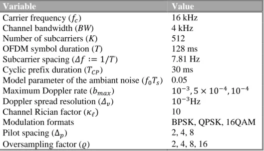
Table 2.1Comparison of acoustic, EM and optical waves in underwater medium Acoustic Electromagnetic Optical Nominal speed (m/s) ~ 1500 ~ 33 333 333 ~ 33 333 333 Power loss relatively small large ∝ turbidity
Bandwidth ~ kHz ~ MHz ~ 10 - 150 MHz
Frequency band ~ kHz ~ MHz ~ 1014 - 1015Hz
Antenna size ~ 0.1 m ~ 0.5 m ~ 0.1 m
Effective range ~ km ~ 10 m ~ 10 - 100 m
2.3 Characteristics of Underwater Acoustic Channel
Acoustical signals experience a different type of dilemmas other than those that can be found in terrestrial communication over EM or optical waves. In the next context, part of the characteristics that distinguish underwater acoustical communication will be
9
introduced, which make underwater acoustical channel one of the most challenging channels for wireless communication.
2.3.1 Sound Velocity
The propagation speed of the sound signals is extremely slow compared to the EM and optical waves. The average speed of acoustic signals in underwater medium is 1500 m/s (Wang and Wang, 2016). Acoustic signals propagate with different speeds in underwater environments. Basically, the acoustic signals propagate with different speeds that depend on the depth, the water temperature, and the water salinity (Porter, last accessed, 2018). However, a typical speed of sound in water near the ocean surface is about 1520 m/s, which is more than 4 times faster than the speed of sound in air (~ 343 m/s), but five orders of magnitude smaller than the speed of light. The water layers can be categorized into three main layers (Zhou and Wang, 2014)
Surface layer: this layer is also referred to as mixed layer. The depth of this layer is within tens of meters away from the water surface, where the salinity and the temperature of the water in this layer tend to be homogenous (due to the effect wind) that leads to a constant sound velocity of the acoustic waves. This layer is also called shallow water.
Seasonal and permanent thermocline layers: this layer is the second deeper layer than the surface layer, where the water temperature decreases in this layer as the depth increases, and the temperature varies from season to season.
Deep isothermal layer: in this layer, the temperature is almost constant for all depths, where the water pressure plays role in determining the acoustic wave speed.
2.3.2 Propagation Loss
The strength of the received signal is quite related to the placement of base stations, in the underwater environment. Based on the surface (sea conditions) and the bottom topology of the underwater area, each channel gain can be assumed to have different distribution statistical characterization. For instance, when the receiver is in shallow water and close to the transmitter, diffuse random multipath contributions are negligible and the
10
channel tap gains can be assumed to obey the Rician distribution. On the other hand, with increasing distance between the transmitter and the receiver, the large sea dynamics prevent direct path contributions, and consequently, the diffuse multipaths dominate, resulting in the channel gains having Rayleigh distribution. Since the underwater communication topology is in a continuous change, the channel tap gains may also obey other type of distributions, such as log-normal and Nakagami-m distributions.
Acoustical waves experience two different energy loss factors while propagation in underwater medium. Mainly, the absorptive and the scattering (the bottom and the surface loss) loss due to the geometry of the underwater region. The scattering of sound coming from the sea surface and the scattering and the absorption of the sound waves from the sea floor can also contribute significantly into signal attenuation and dominant when the base stations are placed in shallow water.
Finally, the refraction and reflection of sound (which mainly depend on the sea conditions, sea floor type, isothermal layer depth, sudden and unexpected temperature changes in underwater etc.,) can create the so called phenomena shadow zone resulting in a significant attenuation of signal energy (Nguyen et al., 2009). Due to the scattering and the large fading of the acoustic signals, the channel impulse response is considered to be a time variant sparse channel, and only received taps with significant powers are considered.
2.3.2.1 Absorptive Loss
In general, underwater applications operate in low frequency, where the pH of the water in the underwater region plays an important role in the attenuation, that is, the higher the pH, the larger the attenuation, where an accurate attenuation computation is a must (Browning et al., 1988). In underwater medium, the energy of acoustic wave converts to heat. The frequency-dependent loss experienced by acoustic waves occurs due to the existence of the chemical substances (boric acid 𝛼1, magnesium sulphate 𝛼2, and viscosity of water 𝛼3). Different contributions on underwater absorption were made for
a better acoustic wave attenuation estimation. The frequency-dependent loss can be expressed as (Moll, et al., 2009):
𝛼 = 𝛼1 + 𝛼2+ 𝛼3, (2.1)
11 𝛼1 = 𝐴1 𝑓1𝑓 2 𝑓12+ 𝑓2𝑒(𝑝𝐻−8)/𝑃1 o 𝑓1 = 𝐹1 ( 𝑆 35) 𝑠1 𝑒𝑇/𝑇1, 𝛼2 = 𝐴2 (1 + 𝑇 𝜃2) ( 𝑆 35) ( 𝑓2𝑓2 𝑓22+ 𝑓2) 𝑒 −𝑧/𝑍2, o 𝑓2 = 𝐹2 𝑒𝑇/𝑇2, 𝛼3 = 𝐴3𝑃3𝑓2,
where 𝐴3 and 𝑃3 can be estimated as follows:
o 𝐴3 = 4.937 10−4− 2.59 10−5 𝑇 + 9.11 10−7𝑇2− 1.5 10−8 𝑇3 , for
𝑇 ≤ 20 °C,
o 𝐴3 = 3.964 10−4− 1.146 10−5 𝑇 + 1.45 10−7𝑇2− 6.5 10−10 𝑇3, for
𝑇 > 20 °C,
o 𝑃3 = 1 − 3.83 10−2𝑧 + 4.9 10−4 𝑧2,
where 𝑓 is in kHz, pH in NBS, salinity (S) in g/kg, temperature (T) in Celsius, depth (z) in km. The formula results in an absorption value measure in decibels per kilometer (dB/km). For simplicity, a simplified version of the attenuation formula can be used called Thorpe attenuation which can be expressed as (Zhou & Wang, 2014):
𝛼𝑇ℎ𝑜𝑟𝑝𝑒(𝑓) = 40 𝑓
2
4100 + 𝑓2+
0.1 𝑓2
1 + 𝑓2 (2.2)
where 𝑓 is the carrier frequency in kHz and 𝛼𝑇ℎ𝑜𝑟𝑝𝑒 is in units of dB/m. For the case of an ultra-high frequency (UHF) deployment is assumed in underwater mediums (up to 10 GHz), Akhiezer and Landau-Rumer type of attenuation should be considered (Telichko, et al., 2015).
2.3.2.2 Scattering Loss
In underwater medium, the scattering loss of the sound waves increases as the acoustic wavelength decreases. Scattering in underwater is induced by the roughness of the water surface and sea bottom, whereas high interface roughness induces large spatial energy dispersion. The scattering occurred by the bottom mainly depends on the roughness of the geology of the sea bottom such as, sand ripples, and roughness of the rocks.
12
An important scattering parameter in the surface side is the environmental conditions of the sea, that is, in the presence of high wind, where the wind-generated waves increases the roughness of sea surface, and the higher the scattering order is experienced (Yuan et al., 2016).
2.3.3 Ambient Noise and Interference
In any communication system, signal-to-noise ratio (SNR) is very essential for ensuring a smooth and reliable carriage of the transmitted data. SNR, however, gives a comparison of the strength of the intended signal to that of the noise. In underwater acoustical communication, depending on the sea conditions, the acoustic channel can be considerably affected by the ambient noise generated by the diverse origins.
The ambient noise experienced in underwater environment is relatively high. Different natural sources of noise such as surface waves, rainfall, biological sources (marine mammal vocalizations, snapping shrimp) and other man-made sources (underwater machineries, ships and boats) affect the acoustic communication in underwater medium (Chitre et al., 2006) (Guimarães et al., 2014). For instance, in (Adzhani et al., 2016), the experiment shows a wind noise of 50 dB, where the experiment in (Prince et al., 2015), shows an aerial noise in the range of [46.8, 53] dB, where the rainfall (depending on the precipitation) can produce noise up to 50 dB, whereas noise spectrum level decreases with increasing frequency from about 140 dB at 1Hz to 30 dB at 100 KHz (Santoso et al., 2015). Consequently, modulation order in underwater coherent communication systems plays an important role in data detection at the receiver side. SNR can be given in the following formula:
𝑆𝑁𝑅(𝑑, 𝑓) = 10 log10 (𝑃𝑆) − 𝑇𝑙− 10 log10 (𝑃𝑁), (2.3)
where 𝑃𝑆 is the total signal power, 𝑇𝑙 is the transmission lose, 𝑃𝑁 is the total noise power,
and the final result of SNR is then measured in dB. However, the transmission loss 𝑇𝑙 presented in (2.3)is a function of the distance, (d) and the attenuation factor 𝛼(𝑓) (discussed in subsection 2.3.2.1). It was stated in (Iqbal et al., 2013), that the total noise power (𝑃𝑁) can be divided into four main sources, mainly, noise generated by ships
activities, noise generated by wind, noise generated by heat, and noise generated by turbulence. Consequently, the noise equation can be formulated as:
13 𝑁(𝑓) = 𝑁𝑠(𝑓, 𝑆) + 𝑁𝑤(𝑓, 𝑊) + 𝑁ℎ(𝑓) + 𝑁𝑡(𝑓), (2.4) where 𝑁𝑠(𝑓, 𝑆) = 40 + 20 (𝑠 − 0.5) + 26 log10(𝑓) − 60 log10(𝑓 + 3), 𝑁𝑤(𝑓, 𝑊) = 50 + 7.5√𝑤 + 20 log10(𝑓) − 40 log10(𝑓 + 0.4), 𝑁ℎ(𝑓) = −15 + 20 log10(𝑓), 𝑁𝑡(𝑓) = 17 − 30 log10(𝑓).
There exist huge efforts for acoustical noise estimation and measurements in underwater environments, i.e., QUONOPS and LIDO systems (André, et al., 2016). QUONOPS system is connected to several underwater sensors at different bathymetries, while temperature and salinity measurements process is carried on. In LIDO is responsible for automatic processing of an acoustic data from the observed signals. Basically, it measures the noise levels, then identifies the acoustic source that contributed to the measured acoustical noise. Finally, an online interface can be accessed for real-time monitoring. On the other hand, the EU Ocean of Tomorrow program has started AQUO project to achieve quieter oceans by shipping noise footprint reduction. The was methodology was to take into account all the key components and measurements of noise coming from ships as the noise source at the receivers, basically sensors. The procedure they pursued is presented in Fig. 2.1 (André, et al., 2016).
14
However, the main two parts of their study regarding the man-made noise reduction are:
A noise footprint assessment tool development was formed,
A development of the radiated noise model of ships was developed, that consider a variety of commercial ships and their corresponding characteristics.
However, depending on the underwater area and sea conditions, the noise modelling for wireless acoustical communication in such environment has been growing. For instance, (Liling and Dupeng, 2017) came up with a solution for underwater noise stimulated by an airborne source. The study uses the propagator matrix and the wave number integration to establish an air and underwater acoustic field spatial distribution model stimulated by the moving source in the air.
2.3.4 Large Doppler Shift
Due to the nature of acoustic signals, a major change in the wavelength (frequency) of the sound wave that arises as a result of the medium instability (i.e., movement of the transmitter/receiver due to wind) (Beygi and Mitra, 2015). This kind of frequency change is referred to as Doppler shift or Doppler effect. Because the moving surface of the sea, the Doppler shifts have an unpredictable variant values. Consequently, underwater acoustic communications (UWACs) are fragile to Doppler shift, where the relatively low sound speed in underwater medium generates a large Doppler shift. For example, in the presence of an acoustic wireless communication with a carrier frequency centered at 𝑓𝑐 = 20 kHz, where the average velocity of the sound wave in underwater medium is approximately. 1500 m/s, thus the Doppler shift induced by the moving sea surface for a system placed in shallow water with a received line of sight (LOS) signal can be determined as (Ha et al., 2017):
𝑓𝑇X𝑆𝑛 = 𝑉𝑆𝑛 × 𝑓𝑐 𝐶𝑆 cos(𝜃𝑆𝑛) = 1.5 × 20,000 1500 = 20 Hz,
where 𝜃𝑆𝑛 is the angle between the surface-normal velocity 𝑉𝑆𝑛and the scatterer-transmitter axis, 𝐶𝑆 is the speed of the acoustical signal. For the case when the received signal is a scattered component, the Doppler shift formula can be expressed as:
𝑓𝑆𝑛𝑅X = (𝑓𝑐+ 𝑓𝑇X𝑆𝑛) ×
𝑉𝑆𝑛
15
where 𝜃𝑅𝑛is the angle between the surface-normal velocity 𝑉𝑆𝑛 and the scatterer-receiver axis, and the total Doppler shift generated by the sea surface can be expressed as:
𝑓𝐷,𝑆𝑛 = 𝑓𝑆𝑛𝑅X+ 𝑓𝑇X𝑆𝑛.
However, Doppler shift can also arise due to the movement of the receiver, and thus, can be given by this formula
𝑓𝑖,𝑛 = 𝑓𝑐 × 𝑉𝑅
𝐶𝑆 cos(𝛼𝑖𝑛) cos(𝜋 − 𝛼𝑉
𝑅),
where 𝑓𝑖,𝑛 is the resulting Doppler shift of the 𝑛𝑡ℎpath 𝛼𝑖𝑛 is the angle of arrival (AOA), and 𝑖 = 1, 2 which denotes the signal is reflected from surface (i=1) or bottom (i=2), respectively.
2.3.5 Long propagation Delay
Multipath spread is a significant characteristic of the underwater acoustic communication channels affecting the channel impulse response at the receiver side, where the long propagation delay experienced in this region is due to the low sound speed. In addition, the reflection of the sound wave off the sea surface and sea floor as well as the refraction of sound such as bending rays of the propagation paths create many different propagation paths, and hence, the underwater channel is considered to be time-variant. Mainly, the nature of the underwater environment is responsible of creating the multipath channel, where the longer the communication range, the longer the delay experienced at the receiver side. The wave reflections from the surface and the bottom generate several arriving taps (sparse type of channel with large delay spread) can be observed at the receiver in applications that use transmitter/receiver placement in shallow water, whereas, the applications where transmitter/receiver are placed in deep water, the surface and bottom reflections can be neglected (Zhou and Wang, 2014)] (Nguyen et al.,2009) (Mason et al., 2008).
2.3.6 Multipath Propagation and Channel Models
Channel modelling provide an excellent tool for predicting the performance of underwater acoustic communication systems before their deployment, and, of course, they are very essential for system design.
16
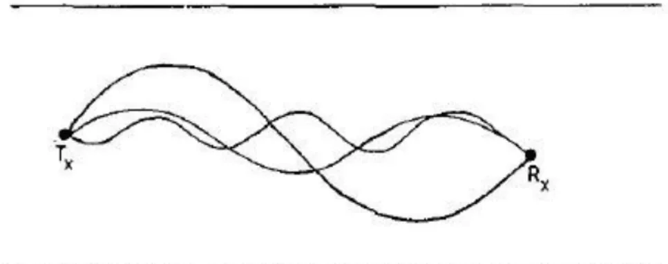
One of the essential dilemmas in the underwater acoustical communication is the corruption of the data, due to multipath interference. Underwater acoustic communications suffer from the time variant type of channel. A particular underwater channel can be represented depending on the sea conditions, the range of communication, and the depth of the stations. At the receiver, the received signals can be direct, reflected, scattered from the surface and bottom, or refracted by variations in the acoustic velocity profile, which lead to multipath propagation. Thus, the received signals then suffer from severe and rapid amplitude fluctuations and fading. When the communication range is short, then the receiver will experience a direct path (steady component), and different random paths (diffused components) which can be as a result of boundary scattering. In the case of long communication range, the received signal is then a superposition of a number of time-delayed, randomly propagated components arriving via different paths (Falahati et al., 1991).
Figs 2.2 and 2.3 attempt to simulate the time-varying characteristics of underwater channels observed experimentally.
Figure 2.2 Short-range propagation.
17
Multipath causes a receiving of a series of pluses at the receiver, that are originally a single impulse sent from the transmitter. In the case of a multiple echoes, the received data can overlap in time, thus, become degraded. This type of interference can be largely avoided by using asynchronous serial transmission. In this type of transmission, the transmitter sends of short signal, each followed by a much longer quiet period. However, a suitable arrangement of the transmitting and receiving transducers has to be made. However, all the signals are then received before the next burst is transmitted.
Successful channel models that can be found in the literature are based on statistics. Mainly, a statistical channel model encounter physical laws of acoustic propagation (frequency-dependent attenuation, bottom/surface reflections). In addition, these statistical channel models reflect the effects of inevitable random local displacements. Specifically, random displacements that involve distances on the order of a few wavelengths (small-scale effects), and those that involve many wavelengths (large-scale effects). The small-scale type of effects includes the scattering and the motion-induced Doppler shifting. The aforementioned effects are responsible for the fast variations of the instantaneous channel response. On the other hand, the large-scale type of effects describes the location uncertainty and the changing environmental conditions, and thus, affects the averaged power of the received signals. Since the transmission conditions in the underwater environment differ from the nominal ones due to the changes in system geometry and environmental conditions. Consequently, the necessity of having a
relatively accurate channel model is a must. However, the channel model is responsible
for allocating the appropriate resources (power, bandwidth) before system deployment, as well as to examine the pre-designed signals processing techniques on both the physical link layer and the higher network layers. Channels can be generated at labs. Using a ocean
wave basin, a real underwater channel can be modeled. Moreover, an experimental type
of channel is always preferred to study the behavior of channel estimators. Experimental channels take into consideration the exact depths of the underwater area, the sediments, the Doppler scales per path, real-time delays, and the exact type of sea bottom including the what exist at the bottom i.e.,sand ripples roughness of the rocks. However, a technique for channel modeling known as beam tracing that consider underwater acoustic communications can be found in an acoustical toolbox known as BELLHOP, more about BELLHOP is discussed in the next section.
18 2.4 Bellhop Acoustic Toolbox
In this section, an overview about BELLHOP acoustical toolbox will be given. Note that, BELLHOP is an open source software, and it does not come in a standalone fashion, it comes wrapped in another compiler, i.e. MATLAB-wrapper BELLHOP.
2.4.1 Overview
Bellhop is a set of algorithms that trace the ray in underwater environment. It was originally written in Fortran language, later on, programmers prepared many versions of Bellhop written in different languages to support different operating systems (Porter, last accessed, 2018). BELLHOP uses ray theory to provide an accurate deterministic picture of the underwater channel.
In addition, Bellhop is capable of producing various useful outputs such as, ray coordinates, travel time and amplitude forming channel impulse response, eigenrays, and transmission loss. The ray trace, which shows the propagation paths of the acoustic signals for the given underwater region and communication specifications along the communication range. In addition, user can find the channel impulse response through requesting the time of arrival and amplitude of the arriving acoustic signals. In order to run Bellhop, the user inputs the sound speed profile associated with the specifications of the underwater region, and requests the desired output.
Bellhop considers sea surface heights with a single valued function of position and time, whereas in Virtex (Virtual Timeseries EXperiment), which is an update version of Bellhop, it approximates the motion of the environment itself by a sequence of snapshots with different heights instead of one snapshot as in Bellhop. In addition, Virterx, along with its advancements, has the ability to include the motion of the source, and/or the receiver in its calculation, with an unsteady sea surface motion, where the Doppler introduced by the unsteady sea surface motion is calculated by the eigenray data produced by Bellhop. Virterx was developed to simulate the effect of channel variation in a manner that is computationally more efficient than repeated application of the Bellhop beam tracing. This algorithm operates by tracing multiple interrelated beams to assess the cumulative effect on the signal of a given frequency. However, the complexity of Virterx may still have an issue. For instance, it takes around of 15 seconds for a two-transmitters
19
and six-receivers underwater communication system to simulate a channel using Virterx. In each second, Virtex requires around 30 channel realizations, which leads to a total of 5400 runs of BELLHOP, considering a Doppler distortion of the order of 0.015 KHz (Qarabaqi and Stojanovic , 2013).
2.4.2 Environmental Profile
The input file to Bellhop is called environmental profile. In this profile, the specifications of the underwater region along with the acoustical wireless communication link are imputed in the file manually along with the intended output. The wireless communication link information consists of the carrier frequency, the antenna aperture, the depth and the number of the transmitter/receiver, the number of beams to be sent considered per transmission, and the communication range. In addition, Bellhop offers a set of interpolation techniques (cubic spline interpolation, C-linear interpolation, N2-linear interpolation, and analytic interpolation) where user can specify the technique in order to find the sound speed and its derivatives along the ray.
Moreover, different acoustic pressure approximations are proposed by Bellhop to be inserted in the environmental profile (geometric beams, Cartesian beams, use ray-centered beams, Gaussian beam bundles). In addition, attenuation can be specified in different units (dB/m (kHz), Nepers/m, Q-factor, and dB/wavelength). However, Bellhop gives the ability for users to include the surface type and bottom shape as flat shaped or user can include them using an external file for a better ray tracing and arrival signal channel. One of the most important aspects of the communication over acoustic signals in underwater environment is the sound speed profile. This profile reflects the speed of the signal at different depths in the underwater region.
In other words, according to the transmitter/receiver depths, the signal propagates in the underwater region towards the bottom of the underwater region and the surface sides, where the speed of the sounds is not constant along the depths, consequently the channel impulse response is affected. Unfortunately, BELLHOP does not encounter the random channel variation (Qarabaqi and Stojanovic, 2013).
In order to cope with channel modeling, different studies were carried on modelling the UWA channel stochastically, e.g., (Qarabaqi and Stojanovic, 2009) (Ruiz-Vega, Clemente, Otero, & Paris, 2012). However, these studies were shaped based on the
20
analysis of an experimental type of an acoustic data, collected in a particular location. Depending on the system model of the study, the underwater channel was found to obey a Rician fading (Qarabaqi and Stojanovic, 2009), (Radosevic et al., 2009) or Rayleigh fading (Socheleau et al., 2009), (Galvin and Coats, 1996), (Chitre M. , 2007).
In addition, fading of underwater channels was also detected to follow log-normal distribution (Qarabaqi and Stojanovic, 2011) (Tomasi et al., 2010), K-distribution (Yang and Yang, 2006) (Zhang et al., 2010), and a general class of Rician shadowed distribution (Ruiz-Vega et al., 2012).
2.4.3 Sound speed profile
In order to fulfill the task of Bellhop, the sound speed profile (SSP) consists mainly of the sound speeds at different depths. In the case of lack of information regarding the underwater region; users can estimate the sound speed profile through various formulas, such as Medwin formula as follows (Bahrami et al., 2016):
𝑆𝑆𝑃(𝑇, 𝑆, 𝐷) = 1449.2 + 4.6𝑇 − 0.055𝑇2+ 0.00029𝑇3
+ (1.34 − 0.01𝑇) (𝑆 − 35) + 0.016𝐷. (2.5)
The formula shows that the speed of acoustic signal in underwater medium grows when any of the parameters (T, S, D) increases. At a certain depth, depending on the water temperature, water salinity, and water depth, the formula accurately calculates the speed of the acoustic signal at that specific depth, and the resulting value is the sound speed that can be used along with the corresponding depth in the SSP of Bellhop’s environmental profile.
21
3. SPARSE CHANNEL ESTIMATION AND DATA DETECTION
FOR OFDM-BASED UNDERWATER ACOUSTIC SYSTEMS IN
RICIAN FADING
In the following sections and subsections, two new pilot assisted channel estimation techniques that employ OFDM transmission scheme in doubly-selective Rician UWA channels are proposed. The chapter fully discusses the first algorithm and presents its simulation results, then the second algorithm, which is an extension of the first one, is then presented with simulations.
3.1 Introduction
The main contribution in this work is twofold. First, the sparse structure of the UWA channel impulse response is exploited to improve the performance of the channel estimation algorithm, due to the reduced number of taps to be estimated. The resulting algorithm initially estimates the overall sparse channel tap delays and the Doppler shift by using a conventional matching pursuit (MP) algorithm (Cotter & Rao, 2002) (Zhang, Han, Huang, & Nramdt-Pearce, OFDM transmission over time-varying channel with self interference cancellation, 2014), assuming correlated ambient Gaussian noise affecting the system from source to destination.With the path delays and Doppler spread information, then a computationally efficient and low complexity novel channel estimation algorithm is proposed by combining MP and maximum a posteriori probability (MAP) estimation to estimate the complex channel path gains whose prior densities have Rician distributions with unknown means and variances. They are, in turn, estimated separately by the maximum likelihood (ML) technique. The likelihood function of those parameters is determined by properly averaging it over the Rician distributed complex channel gains.
22
This chapter is organized as follows. Section 3.2 presents the system and channel model for an OFDM-based underwater wireless communication system and describes the main parameters of the UWA channel and the ambient noise. Section 3.3 proposes the new sparse channel estimation algorithm. Section 3.4 describes the equalization and detection algorithms for the overall OFDM based UWA communications system. The computation complexity is presented in 3.5, and the computer simulations with BELLHOP simulated channels in Sapanca Lake are presented in 3.6. Section 3.7 presents the second proposed approach which extends the work to a non-uniform Doppler scale and use orthogonal matching pursuit (OMP) instead of MP in the case of white noise. All related equations and simulations of this extension can be found under subsection 3.7. Finally conclusions regarding the two approaches are presented in section 3.8.
3.2 System and Channel Model
The proposed UWA communication scenario is OFDM-based in which a single-antenna source node S transmits information to a single-antenna destination node D. The UWA channel between source and destination nodes is characterized by multipath propagation, typically with a few significant paths, resulting in a sparse multipath channel model (Mason, Berger, Zhou, & Willett, 2008). This type of channels can be represented by a parametric channel model, consisting of a limited number of distinct paths parameterized by the path delays and path gains. The parametric channel model effectively reduces the dimension of the signal estimation problem, and the corresponding channel estimation can achieve better performance than that of non-parametric channel model-based estimators.
The time-varying UWA channel impulse response (CIR) from source to destination (S ⟶ D) link is sparse and characterized by
ℎ(𝑡, 𝜏) = ∑ 𝐴ℓ(𝑡) 𝛿(𝜏 − 𝜏ℓ(𝑡))
𝐿−1
ℓ=0
(3.1)
where, 𝐿, 𝐴ℓ(𝑡) and 𝜏ℓ(𝑡) denote the number of non-zero paths, the real channel path
amplitudes and the time-varying path delays, respectively. In this work, the path gains are assumed on each link to remain constant over one OFDM symbol transmission and vary independently from symbol to symbol. That is, 𝐴ℓ(𝑡) = 𝐴ℓ, ℓ = 0, 1, … , 𝐿 − 1.
23
The continuously time-varying delays 𝜏ℓ(𝑡) are caused by the motion of the transmitter/receiver as well as scattering of the moving sea surface or reflections due to sound speed variations (Mason, Berger, Zhou, & Willett, 2008). For the duration of an OFDM symbol, the time variations of the path delays can be approximated well by a Doppler rate as 𝜏ℓ(𝑡) = 𝜏ℓ− 𝛾𝑡 (Kuai, Sun, & Cheng, 2016) (Beygi & Mitra, 2015). The path delays, 𝜏ℓ, are assumed to be constant over an OFDM symbol duration and all paths
have a similar Doppler scaling factor, that is 𝛾ℓ ≡ 𝛾. However, in general, the Doppler scaling factor can be different for each path (Mason, Berger, Zhou, & Willett, 2008). However, it was stated in (Li, et al., 2009) that as long as the dominant Doppler shift is caused by the direct transmitter/receiver motion, this assumption can be justified.
Taking these assumptions and approximations into account, the time-varying continuous-time multipath UWA channel impulse response model above is simplified to
ℎ(𝑡, 𝜏) = ∑ 𝐴ℓ 𝛿(𝜏 − (𝜏ℓ− 𝛾𝑡)) 𝐿−1
ℓ=0
. (3.2)
The baseband equivalent channel impulse response of ℎ(𝑡, 𝜏) in (3.2) can be determined as: ℎ𝑏(𝑡, 𝜏) = ∑ ℎℓ 𝑒𝑗2𝜋𝑓𝑐𝛾𝑡 𝛿(𝜏 − (𝜏 ℓ− 𝛾𝑡)) 𝐿−1 ℓ=0 (3.3) where ℎℓ ≜ 𝐴ℓ 𝑒−𝑗2𝜋𝑓𝑐𝛾𝜏ℓ.
The model in (3.2) deals only with real channel path amplitudes, 𝐴ℓ, obtained from a ray tracing technique. However, there are many diffuse multipath components diffracted or scattered by the rough sea and bottom surface. Consequently, the multipath components will have random phases uniformly distributed over [0, 2𝜋], and by the central limit theorem. In addition, the channel coefficients (taps) ℎℓ’s on the link are assumed to be
complex Gaussian random variables with independent real and imaginary parts.
Based on the sea conditions, each channel gain |ℎℓ| can be assumed to have a different distribution. When the receiver is in shallow water and close to the transmitter, diffuse random multipath contributions are negligible and the channel tap gains may be assumed to obey the Rician distribution. On the other hand, with increasing distance between transmitter and receiver, large sea dynamics prevent direct path contributions and mostly the diffuse multipaths dominate, resulting in the channel gains having Rayleigh