Generalized Theory of Fo
̈rster-Type Nonradiative Energy Transfer in
Nanostructures with Mixed Dimensionality
Pedro Ludwig Hernández-Martínez,
†,‡Alexander O. Govorov,
§and Hilmi Volkan Demir*
,†,‡†LUMINOUS! Center of Excellence for Semiconductor Lighting and Display, School of Electrical and Electronics Engineering, Physics and Applied Physics Division, School of Physical and Mathematical Sciences, Nanyang Technological University, Singapore 639798, Singapore
‡Department of Physics, Department of Electrical and Electronics Engineering, UNAM - National Nanotechnology Research Center and Institute of Materials Science and Nanotechnology, Bilkent University, Ankara 06800, Turkey
§Department of Physics and Astronomy, Ohio University, Athens, Ohio 45701, United States
ABSTRACT: Förster-type nonradiative energy transfer (NRET) is widely used, especially utilizing nanostructures in
different combinations and configurations. However, the
existing well-accepted Förster theory is only for the case of a single particle serving as a donor together with another particle serving as an acceptor. There are also other special cases previously studied; however, there is no complete picture and unified understanding. Therefore, there is a strong need for a complete theory that models Förster-type NRET for the cases
of mixed dimensionality including all combinations and configurations. We report a generalized theory for the Förster-type NRET, which includes the derivation of the effective dielectric function due to the donor in different confinement geometries and the derivation of transfer rates distance dependencies due to the acceptor in different confinement geometries, resulting in a complete picture and understanding of the mixed dimensionality.
I. INTRODUCTION
Semiconductor nanostructures have been studied extensively in the past decade.1−3 Today nanotechnology offers means to assemble and study superstructures, for example, those composed of nanocrystals and biomolecules.4−6 For instance, by using a biomolecular linker, one can assemble crystalline nanoparticles and nanowires into complex structures with new physical and chemical properties.7−10Unique properties result from the quantum confinement and chemical composition of the building blocks of these superstructures (e.g., metal nanoparticles, semiconductor nanocrystals, biomolecules). Furthermore, interactions between these unit elements lead to enhanced properties for the hybrid superstructure. One of the important mechanisms for strong interaction between the building blocks is the nonradiative energy transfer (NRET),
also dubbed Förster-type resonance energy transfer
(FRET).11,12 NRET results from the Coulomb interaction
between excitons confined in the nanostructures. It is an efficient mechanism for coupling optically excited nanostruc-tures. Such coupled superstructures can strongly change their physical properties. In particular, these changes can be observed in optical experiments of characterizing strongly packed structures. In the presence of optical excitation, the Coulomb (dipole−dipole) interaction results in the energy transfer between the elements (or building blocks).7,13−17The resulting energy transfer effect is observed by the directional flow of excitons between the building blocks.
Numerous studies have previously been reported on NRET and related effects in systems of certain dimensionality. For example, several aspects of the energy transfer for nano-particle−nanoparticle, nanoparticle−biomolecule, nanopar-ticle−nanorod, nanoparticle−surface, and quantum well−nano-particle were discussed in refs 8, 14, and 18−24. Also, refs 25−34 studied the energy transfer for the hybrid systems
including nanoparticle−nanowire, nanoparticle−nanorod,
nanoparticle−nanotube, nanowire−nanowire, and
nanopar-ticle−nanosheet. Ref 35 reported chemically controlled
NRET in nanoparticle composites. Nevertheless, to date, a complete unified understanding on the modifications of NRET when using mixed dimensionality, with all possible combina-tions of quantum objects, for example, nanoparticles (NPs), quantum wires, that is, nanowires (NWs), and quantum wells (QWs) lacks. Although the resulting NRET rates are fundamentally modified due to the mixed dimensionality, the distance dependency correlated to the dimension of the donor or the acceptor and their roles in modifying NRET have not been understood. However, understanding these modifications is essential to utilizing these nanostructures for high efficiency light generation and harvesting. Therefore, differentiating these effects with respect to the donor versus the acceptor is critically important.
Received: March 5, 2013
Revised: April 16, 2013
Published: April 16, 2013
In this paper, a complete study of the generalized Fo ̈rster-type NRET between nanostructures consisting of mixed dimensions in confinement (NP, NW, and QW) is presented.
We investigate the modification of NRET mechanism with
respect to the nanostructure serving as the donor versus the acceptor, focusing on the rate’s distance dependency and the role of the effective dielectric constant on NRET. In this work,
the combinations of NW→ NP, QW → NP, QW → NW, and
NW→ QW (where the donor → acceptor (D → A) denotes
the energy transfer directed from the donor to the acceptor) were specifically considered because they have not previously been theoretically studied. Moreover, we obtain a set of analytical expressions for NRET in the cases mentioned above and derive generic expressions for the dimensionality involved to present a unified generalized picture of NRET. Finally, the asymptotic behavior of these equations and the comparisons between all possible cases are presented and discussed.
II. DIPOLE POTENTIAL FOR EXCITON IN A NANOPARTICLE, NANOWIRE, AND QUANTUM WELL
In this section, the analytical equations for the exciton electric potential inside and outside the nanostructures are obtained. For the long distance approximation, a set of convenient expressions for the outside electric potential are also derived.
Moreover, we obtain the effective dielectric constant
expressions in this limit.
A. Nanoparticle Case. The electric potential for an exciton in theα-direction (α = x, y, z) inside a spherical NP, illustrated in Figure 1a, is given by
α ε ε ε ε ε Φ = ̂· + − + α ⎛ ⎝ ⎜ ⎞ ⎠ ⎟ ⎛ ⎝ ⎜ ⎞ ⎠ ⎟ r r R r ed 1 2( ) 2 in exc NP 3 NP 0 NP 0 3 NP 3 (1) α ε ε ε ε Φ = + · ̂ α ⎛ ⎝ ⎜ ⎞ ⎠ ⎟⎛ ⎝ ⎜ ⎞ ⎠ ⎟ r r ed 3 2 out exc NP NP NP 0 3 (2)
where edexcis the exciton dipole moment andεNPandε0are the NP and medium dielectric constants, respectively. The electric potential is the same in any direction because of the spherical symmetry of the NP. In the long distance approximation, the outside electric potential can be simplified as
α ε Φα = · ̂ ⎛ ⎝ ⎜ ⎞ ⎠ ⎟ r r ed out exc eff 3 (3)
whereεeffis the effective dielectric constant given by
ε = ε + 2ε
3 eff
NP 0
(4)
B. Nanowire Case. For the case of a long cylindrical NW, the electric potential forα-exciton (α = x, y, z), shown in Figure 1a, can be written as the sum of the electric potential of the exciton inside the NW plus a second term to account for the boundary between the NW and the outside medium. Thus, the electric potential is expressed as
∫
∑
ρ Φ = Φ +α α | | φ− α e e A k I k k ( ( ) ( ))d m im iky m m in (5) Figure 1.(a) Schematic for an exciton in a NP, NW, and QW. Red circle represents an exciton in theα-direction. RNP(NW)is the NP (NW) radius. LQWis the QW capping layer thickness. Total and long distance approximation electric potentials for the z-exciton inside (b) an NP; (c) an NW; and (d) a QW.dx.doi.org/10.1021/jp402242y| J. Phys. Chem. C 2013, 117, 10203−10212
∫
∑
ρ Φα = Φ +α | | φ− α e e B k K k k ( ( ) ( ))d m im iky m m out (6) where Im(|k|ρ) and Km(|k|ρ) are the modified Bessel functions of order m;φ is the angular component running from 0 to 2π, k is the expansion along the cylinder axis [k∈ (−∞,∞)]; and Φα is the electric potential for anα-exciton inside the NW. After applying the boundary conditions at the surface of the NW, Amα and Bmα coefficients are found to be= | | | | α ⎛ α ⎝ ⎜ ⎞ ⎠ ⎟ A k K k R I k R B k ( ) ( ) ( ) ( ) m m m m NW NW (7) ε ε ε ε = − | | | | + | | α α | | | | | |
(
)
B k g k k R k R ( ) ( ) ( ) ( ) ( ) m k m K k R I k R m m 2 0 NW NW ( ) ( ) NW 0 NW m m NW NW 0 2 (8) w h e r e 0m(| |k RNW)= Im−1(| |k RNW)+Im+1(| |k RNW), | |k R =K − | |k R +K + | |k R ( ) ( ) ( ) m NW m 1 NW m 1 NW 2 , and gmα(|k|) is defined as∫ ∫
π φ ρ | | = ∂Φ ∂ α π φ α ρ −∞ ∞ − = ⎡ ⎣ ⎢ ⎤ ⎦ ⎥ g ( )k 1 d dye e (2 ) m im iky R 2 0 2 NW (9) The outside electric potential, in the long distance approximation, for an exciton in theα-direction, is simplified asα ε Φα = · ̂ ⎛ ⎝ ⎜ ⎞ ⎠ ⎟ r r ed out exc eff 3 (10)
whereεeff is the effective dielectric constant. εeff is given by eq 11 if the exciton is along the cylinder main axis and by eq 12 when the exciton is perpendicular to the cylinder main axis.
εeff =ε0 (11) ε = ε + ε 2 eff NW 0 (12) C. Quantum Well Case. A thin QW embedded in a semi-infinite dielectric medium is considered, as depicted in Figure 1a. In a similar manner as the previous case, the electric potential can be written as the sum of the electric potential of the exciton inside the dielectric medium plus a second term to include the change between the dielectric and outside media. Therefore, the electric potential in the cylindrical coordinates for aα-exciton (α = x, y, z) is written as
∫
∑
ρ Φ = Φ +α α φ α ∞ − kdke J k A( ) ( )cosh( )k kz m im m m in 0 (13)∫
∑
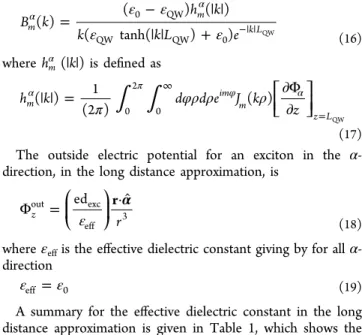
ρ Φα = Φ +α − | | φ α ∞ − kdke J k B k( ) ( )exp( k z) m im m m out 0 (14) where Jm(kρ) is the Bessel function of order m, φ is the angular component running from 0 to 2π, k is the expansion along the cylinder radius, and the electric potential for anα-exciton inside the QW isΦα. The boundary conditions at the surface of the QW yield the coefficients Amα and Bm α = −| | | | α ⎛ α ⎝ ⎜⎜ ⎞⎠⎟⎟ A k k L k L B k ( ) exp( ) cosh( ) ( ) m m QW QW (15) ε ε ε ε = − | | | | + α α −| | B k h k k k L e ( ) ( ) ( ) ( tanh( ) ) m m k L 0 QW QW QW 0 QW (16) where hmα (|k|) is defined as
∫ ∫
π φρ ρ ρ | | = ∂Φ ∂ α π ∞ φ α = ⎡ ⎣⎢ ⎤ ⎦⎥ h k d d e J k z ( ) 1 (2 ) ( ) m im m z L 0 2 0 QW (17) The outside electric potential for an exciton in the α-direction, in the long distance approximation, isα ε Φ =⎛ · ̂ ⎝ ⎜ ⎞ ⎠ ⎟ r r ed z out exc eff 3 (18)
whereεeffis the effective dielectric constant giving by for all α-direction
εeff =ε0 (19)
A summary for the effective dielectric constant in the long distance approximation is given in Table 1, which shows the
symmetry and screening factors for the electric potential in each case. This screening factor is the result of the interface between the nanostructure (NP, NW, and QW) and the outside medium. As expected, the screening factor for the NP case is the same for an exciton in the x-, y-, and z-directions because of the spherical symmetry. In the cylindrical symmetry (NW case), an exciton in the cylindrical main axis does not have any screening factor because the exciton dipole moment is perpendicular to the cylinder’s normal surface vector. However, an exciton perpendicular to the cylindrical main axis has a screening factor as given in Table 1. The reason for this screening factor stems from that fact that the exciton dipole moment is parallel to the cylinder’s normal surface vector. In the QW case, we do not observe any screening factor for an exciton in the x-, y-, or z-direction. This can be explained due to the fact that we choose the cylinder axis along the z axis and make the limitρ → ∞ to account for an infinite plane (QW). It is worth mentioning that we consider an infinite cylinder for the NW case and an infinite plane for the QW embedded in a semi-infinite dielectric medium. Note that Table 1 follows the geometries sketched in Figure 1.
Figure 1 depicts the total and long distance approximation electric potentials for a z-exciton along the z axis. Figure 1b shows both the total and long distance approximation electric potentials for a z-exciton inside an NP. It is observed that both electric potentials overlap each other because of the spherical symmetry of the nanostructure (eqs 1, 2, and 3). In a similar manner, the total and long distance approximation electric Table 1. Effective Dielectric Constant Summarya
α-direction NP NW QW X ε = ε + 2ε 3 eff NP 0 ε = ε +ε 2 eff NW 0 εeff=ε0 Y ε = ε + 2ε 3 eff NP 0 εeff=ε0 εeff=ε0 Z ε = ε + 2ε 3 eff NP 0 ε = ε +ε 2 eff NW 0 εeff=ε0 aEffective dielectric constant expressions for the cases of NP, NW, and
QW in the long distance approximation. This table follows the geometries given in Figure 1.
potentials for a z-exciton in a long NW are depicted in Figure 1c. In close proximity to the NW surface, the long distance approximation underestimates the exciton electric potential, as it is shown in Figure 1c. In the QW case, the long distance approximation overestimates the exciton electric potential in the close proximity to the QW surface (Figure 1d). This is an opposite effect compared to the NW case. In all cases, at long distances the total electric potential converges to the long distance approximation (Figure 1b−d).
III. THEORETICAL FORMALISM FOR FÖRSTER-TYPE NONRADIATIVE ENERGY TRANSFER
In this section, we outline the macroscopic approach to the problem of dipole−dipole energy transfer. We restrict ourselves to the case of a single electron−hole pair (exciton) in the donor nanostructure. Moreover, we consider only two states|0⟩- the ground state and |exc⟩- the excited state. These states are
considered using simplified wave functions such that we
consider excitonic states without the mixing between the heavy- and light-hole states. Furthermore, the spin part is not considered in our model.
NRET is a directional process, which is initiated by an absorbed photon in a donor generating an exciton in a higher excited state and then the exciton relaxing very fast to thefirst excited state by higher order processes. This exciton can subsequently be either recombined (through a radiative or nonradiative means) or transferred to an acceptor because of the Coulomb interaction between dipoles in the D−A pair. If the exciton is transferred, it will occupy a higher excited state in the acceptor and relax (very fast) to its first excited state to finally recombine through a radiative or nonradiative process. NRET occurs only when the donor possesses a greater or equal band gap compared to the acceptor. The diagram for the energy transfer process is shown in Figure 2.
The probability of an exciton transfer from a donor nanostructure (donor) to an acceptor nanostructure (acceptor) is given by the Fermi’s Golden rule (eq 20).
∑
γ = δ ω ω ℏ |⟨f | ̂ |V i ⟩| ℏ − ℏ 2 { ; 0 ; 0 ( )} f ftrans exc exc int exc exc 2 exc
(20) where|iexc;0exc⟩ is the initial state with an exciton in the donor and zero exciton in the acceptor;|fexc;0exc⟩ is the final state with an exciton in the acceptor and zero exciton in the donor; V̂intis the exciton Coulomb interaction operator; and ℏωexc is the exciton’s energy. Neglecting the coherent coupling between excitons, the initial andfinal states can be written as |iexc;0exc⟩ = | iexc⟩|0exc⟩ and |fexc;0exc⟩ = |fexc⟩|0exc⟩, respectively, and the Fermi’s Golden rule can be approximated by
∑
γ ≈ δ ω ω ℏ |⟨f | ̂ |U ⟩| ℏ − ℏ 2 { 0 ( )} f ftrans exc int exc
2 exc
(21)
where Ûint=⟨|0exc|V̂int|iexc⟩ is the potential energy created by the exciton. With this approximation, the Fermi’s Golden rule can be simplified with the used of the fluctuation dissipation theorem (FDT)36together with the QD formalism developed in refs 27 and 37. Thefinal expression for the transfer rate is given by
∫
γ ε ω π = ℏ · * ⎡ ⎣ ⎢ ⎛ ⎝ ⎜ ⎞⎠⎟ ⎤ ⎦ ⎥ dV E r E r 2 Im ( ) 4 ( ) ( ) trans A in in (22)where the integration is taken over the acceptor volume,εA(ω) is the dielectric function of the acceptor, and Ein(r) includes the effective electric field created by an exciton at the donor side. The electricfield is calculated with E(r) = −∇Φ(r) and the electric potentialΦ(r) is given by
α ε Φ = − · ̂ | − | α ⎛ ⎝ ⎜⎜ ⎞⎠⎟⎟ r r r r r ( ) edexc ( ) eff 0 0 3 D (23)
where edexcis the dipole moment of the exciton andεeffDis the
effective dielectric constant of the donor, which depends on the
geometry and the exciton dipole direction, α = x, y, z.
Furthermore, the average NRET rate (at room temperature) is calculated as γ γ γ γ = + + 3 x y z trans
,trans ,trans ,trans
(24)
whereγα,transis the transfer rate for theα-exciton (α = x, y, z).
A. Nanowire → Nanoparticle and Quantum Well →
Nanoparticle Energy Transfer Rates. The NRET rate analytical equations, when the donor is a NW or a QW and the acceptor is a NP (Figure 3a and b, respectively), are derived. Moreover, in the long distance approximation, we obtain simplified expressions for the transfer rate for these cases (NW → NP and QW → NP). Assuming that the donor size is smaller than the separation distance between the D−A pair and using the spherical symmetry of the acceptor, the total electric potential for the acceptor can be written as
∑
θ ϕ θ ϕ θ ϕ Φα = Φα + α + r r B r Y ( , , ) ( , , ) ( , ) l m l m l l m out , , 1 , (25) Figure 2.Energy diagram for the directional process of exciton transferfrom the donor to the acceptor. Blue dash lines represent the absorption process of the nanostructure (donor/acceptor). Blue solid lines denote fast relaxation process. Red dash lines show light emission process (relaxation from the lowest excited state to ground state). Black solid lines represent the energy transfer from the donor to the acceptor. Horizontal solid black line illustrates the Coulomb interaction between the donor and the acceptor.27.
dx.doi.org/10.1021/jp402242y| J. Phys. Chem. C 2013, 117, 10203−10212
∑
θ ϕ θ ϕ Φα = α r A r Y ( , , ) ( , ) l m l m l l m in , , , (26)whereΦα (r,θ,ϕ) is the electric potential of the exciton in the donor; Yl,m(θ,ϕ) are the spherical harmonics; and Al,mα and Bl,mα are the coefficients determined by the boundary conditions at the surface of the NP [Φαin(r = R
NPA,θ,ϕ) = Φα out(r = R NPA,θ,ϕ) and εin((∂Φαin(r,θ,ϕ))/(∂r))r=R NPA = εout((∂Φα out(r,θ,ϕ))/ (∂r))r=RNPA]. εin(out) is the dielectric function inside (outside)
the acceptor. After applying the boundary conditions we obtain
= + α α α + A B R f R l m l m l l m l , , NP 2 1 , NP A A (27) ε ε ε ε = − + + α α + ⎜⎛ α ⎟ ⎝ ⎞⎠ B R g l l (l 1) l m l l m f R , NP 2 out , in in out l m A , NPA (28)
with fl,mα and gl,mα , which are given by
∫ ∫
θ ϕ θ ϕ θ θ ϕ = Φ * α π π α = fl m, 0 [ ( , , )]r r R Yl m( , )sin( )d d 2 0 NPA , (29)∫ ∫
θ ϕ θ ϕ θ θ ϕ = ∂Φ ∂ * α π π α = ⎡ ⎣⎢ ⎤ ⎦⎥ g r r Y ( , , ) ( , )sin( )d d l m r R l m , 0 2 0 , NPA (30)andεout=ε0is the dielectric constant of the medium, andεin= εNPAis the dielectric function of the acceptor. Thus, the energy
transfer rate is
∑
γ ε ω π = ℏ | | · · α α + ⎜ ⎟ ⎡ ⎣ ⎢ ⎢ ⎛ ⎝ ⎞ ⎠ ⎤ ⎦ ⎥ ⎥ A l R 2 Im ( ) 1 4 l m l m l ,trans NP , , 2 NP 2 1 A A (31)where Al,mα is given by eq 27. This is a general expression valid under the assumption mentioned above. From eq 31, it is observed that the distance dependency for the transfer rate is given by the coefficient Al,mα . The asymptotic behavior (in the long distance limit) for the transfer rate in the dipole
approximation for NW → NP and QW → NP is derived. In
these cases, we assume that the donor size is small compared to the separation distance d. Under this condition, the transfer rate (γα,trans) is γ ε θ ε ε ω ε ε ω = ℏ × + α α ⎛ ⎝ ⎜⎜ ⎞⎠⎟⎟ b R d 2 ed cos ( ) 3 ( ) 2 Im[ ( )] ,trans exc eff 2 NP3 6 6 0 0 NP exc 0 2 NP exc D A A A (32)
where bα= (1/3), (1/3), and (4/3) forα = x, y, z, respectively; θ0is the angle between d and r;εeffDis the effective dielectric
constant for the exciton in the donor. For the NW-to-NP case, the effective dielectric constant is εeffD=ε0(eq 11) for α = y
(parallel to the cylindrical axis) andεeffD= ((εNW+ε0)/2) (eq
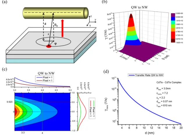
Figure 3.Schematic for the energy transfer of (a) NW→ NP and (b) QW → NP. Red arrows show the energy transfer direction. Red circles represent an exciton in theα-direction. d is the separation distance. θ0is the azimuthal angle between d and r.φ is the radial angle. (c) Average NRET rate for the CdTe D−A QW → NP pair as a function of the distance and angle. (d) Contour profile map for the average NRET rate for the CdTe D−A QW → NP pair, with the top panel at a fixed angle and right panel at a fixed distance.
12), α = x, z (perpendicular to the cylindrical axis). For the QW-to-NP case, it is equal toεeffD=ε0(eq 19) forα = x, y, z.
The NRET rates are proportional to the imaginary part of the acceptor dielectric constant. Thus, an acceptor with high absorption (large Im|εNPA(ω)|) will have higher transfer rates.
Moreover, the transfer rate strongly depends on the distance and θ0. In particular, for the angle dependency, the main contribution comes from smallθ0and decreases very fast asθ0 increases. It is important to notice that the transfer rate in these cases (NW-to-NP and QW-to-NP) follows the same distance dependency as the NP-to-NP transfer rate, which isγ ∝ d−6.38 These results suggest that the NRET rates are dictated by the acceptor’s dimensionality, but not the donor’s.
To illustrate the NRET rate, we present the average NRET rate in the long distance approximation as a function of distance for CdTe D−A pair in Figure 3c,d. Here, we consider the donor to be an NW or a QW and the acceptor to be an NP. In this plot, we assume that the acceptor exciton emission is atλ = 582 nm. In addition, the acceptor dielectric function is taken from ref 39. Figure 3c shows the energy transfer rate for the QW-to-NP case. Figure 3d depicts the contour profile plot for the QW-to-NP transfer rate. The top panel in Figure 3d illustrates the energy transfer rate as a function of the distance at afixed angle. Blue curve represents the case atθ0= 0, and wine curve, atθ0= π/6. The right panel in Figure 3d shows the transfer rate as a function of angle at afixed distance. Red curve represents the case at d = 3.3 nm, and the green curve, at d = 4.0 nm. From Figure 3c,d, the strong distance dependency of the transfer rate
(eq 32) is observed. Therefore, the main contribution for the energy transfer from a QW(NW) to an NP comes at short distances and small angles.
B. Quantum Well→ Nanowire Energy Transfer Rate.
We derive an analytical equation for the NRET rate when the donor is a QW and the acceptor is an NW (Figure 4a). The simplified expression for NRET rate in the long distance approximation is also obtained. Similar to the previous case, we assume that the donor size is small compared to the D−A separation distance d. Taking advantage of the cylindrical symmetry of the acceptor, the total electric potential for the acceptor can be written as
∫
∑
ρ ϕ ρ ϕ ρ Φ = Φ + | | α α α ϕ −∞ ∞ − z z dke B k K k e ( , , ) ( , , ) ( ) ( ) m ikz m m im out (33)∫
∑
ρ ϕ ρ Φα = | | α ϕ −∞ ∞ − z dke A k I k e ( , , ) ( ) ( ) m ikz m m im in (34)whereΦα(ρ, ϕ, z) is the electric potential of the exciton in the donor; Im(|k|ρ) and Km(|k|ρ) are the modified Bessel functions; and Amα(k), Bmα(k) are the coefficients given by eqs 35 and 36. These coefficients are determined by the boundary conditions
Φαin(ρ = RNW A, ϕ,z) = Φα o ut(ρ = RNW A, ϕ,z) and εNW((∂Φαin(ρ,ϕ,z))/(∂ρ))ρ=RN W A = ε0((∂Φα o ut(ρ,ϕ,z))/ Figure 4.(a) Schematic for the energy transfer of QW→ NW. Red arrows show the energy transfer direction. Red circles represent an exciton in the α-direction; d is the separation distance; θ0is the azimuthal angle between d and r;φ is the radial angle. (b) Average NRET rate for the CdTe D−A QW→ NW pair as a function of the distance and angle. (c) Contour profile map for the average NRET rate of QW → NW, with the top panel at a fixed angle, and right panel at a fixed distance. (d) Average NRET rate for CdTe D−A pair with θ0= 0. This plot illustrates the NRET rate distance dependency for the QW→ NW case.
dx.doi.org/10.1021/jp402242y| J. Phys. Chem. C 2013, 117, 10203−10212
(∂ρ))ρ=RNWA, where εNW(0) is the NW and outside medium
dielectric function, respectively.
= | | | | + | | | | α α α A k K k R I k R B k f k I k R ( ) ( ) ( ) ( ) ( ) ( ) m m m m m m NW NW NW A A A (35) ε ε ε ε = | | − | | | | + | | α α α | | | | | | | | | | ⎜ ⎟ ⎛ ⎝ ⎞⎠ B k g k f k K k R k R ( ) ( ) ( ) ( ) ( ) m k m k R I k R m k R I k R m m 2 0 NW ( ) ( ) NW ( ) ( ) NW 0 NW m m m m NWA NWA NWA NWA A 2 A 0 0 (36) w i t h 0m(| |k RNWA)=Im+1(| |k RNWA)+ Im−1(| |k RNWA), | |k R =K + | |k R +K − | |k R ( ) ( ) ( ) m NWA m 1 NWA m 1 NWA 2 , a n d fmα,
and gmα are given by
∫ ∫
π ρ ϕ ϕ = Φ α π α ρ ϕ −∞ ∞ = − f 1 z e e z (2 ) [ ( , , )] d d m 2 0 R ikz im 2 NWA (37)∫ ∫
π ρ ϕ ρ ϕ = ∂Φ ∂ α π α ρ ϕ −∞ ∞ = − ⎡ ⎣ ⎢ ⎤⎦⎥ g 1 z e e z (2 ) ( , , ) d d m R ikz im 2 0 2 NWA (38)The energy transfer rate is written as
∫
∫
∫
∫
∑
γ ε ω π π ρ ρ ρ ρ ρ ρ ρ ρ ρ = ℏ | | | | × | | | | | | + | | | | + | | | | | | α α −∞ ∞ ⎡ ⎣ ⎢ ⎢ ⎤ ⎦ ⎥ ⎥ ⎛ ⎝ ⎜ ⎞ ⎠ ⎟ dk A k k k m I k k I k 2 Im ( ) 4 (2 ) ( ) 4 ( ) d ( ) 1d ( ) d m m R m R m R m ,trans NW exc 2 2 2 0 2 2 0 2 2 0 2 A NWA NWA NWA 0 (39)where Amα(k) (eq 35) gives the distance dependency to the NRET rate. Equation 39 is a general expression, again which is valid under the assumptions mentioned above. In the long distance approximation, the transfer rate equation for the QW-to-NW case is γ ε π θ ε ε ω ε ε ω = ℏ × + + α α α ⎜ ⎟ ⎛ ⎝ ⎜⎜ ⎞⎠⎟⎟ ⎛⎝ ⎞⎠ ⎛ ⎝ ⎜ ⎜ ⎞ ⎠ ⎟ ⎟ R d a b 2 ed 3 32 cos ( ) 2 ( exc) Im[NW( )] ,trans exc eff 2 NW2 5 5 0 0 NW 0 2 exc A D A A (40) where aα= 0, (9/16), (15/16); bα= 1, (15/16), (41/16) forα = x, y, z, respectively; d is the center-to-center distance between the donor and the acceptor; θ0is the angle between d and r; andεeffDis the effective dielectric constant for the exciton in the
donor, which is equal toεeffD=ε0(eq 19) forα = x, y, z. As expected, the asymptotic behavior for the NRET rate of the QW→ NW case follows γ ∝ d−5. This result is similar to the NP-to-NW and NW-to-NW cases, as reported in previous literature, refs 27 and 28, respectively. Similar to the previous section, the NRET rates strongly depend on the distance and θ0, and a similar analysis can be made. In addition, akin to the section above, Figure 4b,c depict the average NRET rate for a CdTe D−A pair as a function of the distance and θ0, when the donor is a QW and the acceptor is an NW. For this plot, we assume that the acceptor exciton emission is atλ = 610 nm and the acceptor dielectric function is taken from ref 39. Figure 4c shows the contour profile map for the QW-to-NW transfer rate. The top panel in Figure 4c illustrates the energy transfer rate as a function of the distance at afixed angle. Blue curve represents the situation atθ0= 0, and wine curve, atθ0=π/6. The right panel in Figure 3c shows the transfer rate as a function of the angle at afixed distance. Red curve represents the behavior at d = 3.3 nm, and the green curve, at d = 4.0 nm. Figure 4d gives the semilog plot for the rates as a function of the distance atθ0 = 0. From Figure 4b−d, the strong distance dependency of the transfer rate (eq 40), can be seen. Therefore, similar to the previous section, the main contribution for the energy transfer from a QW to an NW comes at short distances and small angles.
C. Nanowire→ Quantum Well Energy Transfer Rate.
The analytical equation for the NRET rate when the donor is an NW and the acceptor is a QW (Figure 5a) is derived. Moreover, the simplified expression for the NRET rate in the long distance approximation is also obtained. Similar to the previous cases, we assume that the donor size is small compared to the D−A separation distance d. Furthermore, we consider a symmetric structure, consisting of a semi-Figure 5.(a) Schematic for the energy transfer of NW→ QW. Red arrows show the energy transfer direction. Red circles represent an exciton in the α-direction; d is the separation distance; θ0is the azimuthal angle between d and r;φ is the radial angle. (b) Average NRET rate for a CdTe D−A pair. This plot shows the distance dependency of the NRET rate for the NW→ QW case.
conductor QW of thickness Lw between two barriers of dielectric function εQW. One barrier has a film thickness Ll, while the other barrier is considered to be very thick (we
assume that this barrier is semi-infinite). The donor
nanostructure is placed in front of the barrier with thickness Lland we solve the problem for the case where the QW is very thin (Lw≪ Ll). Under these assumptions, the electric potential inside the barrier is
ε ε ε Φ = + Φα ⎛ ⎝ ⎜⎜ ⎞⎠⎟⎟ r r ( ) 2 ( ) in 0 QW 0 (41)
whereε0is the dielectric constant outside the barrier andΦαis the electric potential of anα-exciton in the QW. Therefore, the transfer rate is
∫
γ ε ε ε ε ω π = ℏ + × * α α α ⎡ ⎣ ⎢ ⎢ ⎛ ⎝ ⎜⎜ ⎞⎠⎟⎟ ⎤ ⎦ ⎥ ⎥ dV E r E r 2 2 Im ( ) 4 ( ) ( ) QW ,trans 0 QW 0 2 A A (42) where Eα(r) is the electricfield created by an α-exciton in the donor. By using the assumption that the QW is very thin (Lw ≪ Ll), the energy transfer rate becomes∫
γ ε ε ε ε ω π = ℏ + × * α α α ⎡ ⎣ ⎢ ⎢ ⎛ ⎝ ⎜⎜ ⎞⎠⎟⎟ ⎤ ⎦ ⎥ ⎥ dS E r E r 2 2 Im ( ) 4 ( ) ( ) ,trans 0 QW 0 2 QW QW A A A (43) where the integration is taken over the surface of the QW. In particular, we obtain the analytical expression in the long distance approximation for NW→ QW. In this case, we assume db≫ Lwwhere dbis the distance from the center of the donor to the dielectric barrier. Under these conditions,γα,transbecomesγ ε ε ε ε ε ω = ℏ + × α α ⎛ ⎝ ⎜⎜ ⎞⎠⎟⎟ b d 2 ed 1 2 Im[ ( )] ,trans exc eff 2 4 0 QW 0 2 QW exc D A A (44) where bα= (3/16), (3/16), (3/8) forα = x, y, z, respectively; d = db+ Llis the distance between the donor and the acceptor; andεeffDis the effective dielectric constant given by εeffD=ε0(eq 11) forα = y (parallel to the cylindrical axis) and εeffD= (εNW+
ε0)/2 (eq 12) for α = x, z (perpendicular to the cylindrical axis). Note that the NRET rate for the NW→ QW case follows the well-known asymptotic behaviorγ ∝ d−4akin to the NP→
QW and QW → QW cases reported in refs 40 and 41,
respectively. Figure 5b shows the average NRET rate for a CdTe D−A pair as a function of the distance, when the donor is an NW and the acceptor is a QW. In this computation, we made similar assumptions as in the previous section.
To summarize our NRET studies, Table 2 lists the transfer rates in the long distance asymptotic behavior in the dipole approximation for all possible combinations with mixed dimensionality. Here, Table 2 illustrates the functional distance dependency for the NRET: (1) when the acceptor is an NP, NRET is inversely proportional to d6(eq 32); (2) when the acceptor is an NW, NRET is proportional to d−5(eq 40); and
(3) when the acceptor is a QW, NRET is proportional to d−4 (eq 44). This indicates that the donor dimensionality (NP, NW, QW) does not affect the functional dependency on the distance. To complete our analysis, we also graphically present the distance dependencies, given in Table 2, in Figure 6 (top panel). Here, the energy transfer rates are given as a function of d/d0, where d0is the characteristic distance, which satisfies the asymptotic condition required for each case (d≫ RNP,(NW), d ≫ LQW). Figure 6 (bottom panel) further illustrates the energy transfer efficiency for the NRET as a function of d/d0. As expected, the fastest decay is possible when the acceptor is an Table 2. Nonradioactive Energy Transfer Rate Summary for the Long Distance Asymptotic Limita
donor(D)\acceptor(A) NPA NWA QWA NPD NPD→ NPA NPD→ NWA NPD→ QWA NWD NWD→ NPA NWD→ NWA NWD→ QWA QWD QWD→ NPA QWD→ NWA QWD→ QWA acceptor distance dependency γ ∝ d 1 NP 6 γ ∝ d 1 NW 5 γ ∝ d 1 QW 4
aThis list shows the distance dependence of the NRET rate given the
acceptor’s geometry. Italics indicates the cases that have not been theoretically studied before.
Figure 6. NRET rate distance dependency in the long distance asymptotic limit (top). Energy transfer rates and efficiencies are plotted as a function of d/d0, where d0is the characteristic distance, which satisfies the asymptotic condition required for each case (d ≫ RNP,(NW), d≫ LQW). Red line shows the case when the acceptor is an NP. Green line illustrates the case when the acceptor is an NW. Blue line depicts case when the acceptor is a QW. In all of them X can be an NP, an NW, or a QW. Energy transfer efficiency for the NRET in the long distance asymptotic limit (bottom).
dx.doi.org/10.1021/jp402242y| J. Phys. Chem. C 2013, 117, 10203−10212
NP and the slowest decay is possible when the acceptor is a QW. In all cases, the NRET’s distance dependency is given by the acceptor geometry and it is independent of the donor’s geometry. Note that the effective dielectric constant, however, depends only on the donor’s geometry. Therefore, we can conclude that the NRET’s distance dependency is dictated by the confinement degree of the acceptor nanostructure, whereas the donor’s confinement affects the modification of effective dielectric constant.
VII. CONCLUSION
In summary, we have obtained a unified picture and
understanding of the nonradiative energy transfer for nanostructures of mixed dimensionality, and completed the
missing cases (NW→ NP, QW → NP, QW → NW, and NW
→ QW) for the NRET rates in all possible combinations. We obtained analytical expressions for the NRET rate in the long distance approximation and compared our results with the ones already reported in the literature and included those cases that have not previously been studied. We showed that the distance dependence of the NRET rate depends on the geometry and dimensionality of the acceptor and on the effective dielectric constant of the donor. The expressions presented in this work will be a convenience reference to estimate the NRET rate for nanostructures involving mixed dimensionalities. In addition, the NRET results obtained here can help in the optimization and the design of new experiments and new devices for high efficiency light harvesting and light generation systems.
■
AUTHOR INFORMATIONCorresponding Author
*Phone: +65-6790-5395. Fax: +65-6793-3318. E-mail: volkan@ stanfordalumni.org.
Notes
The authors declare no competingfinancial interest.
■
ACKNOWLEDGMENTSThis work is supported by National Research Foundation of Singapore under NRF-CRP-6-2010-02 and NRF-RF-2009-09. H.V.D. also acknowledges support from ESF-EURYI and TUBA-GEBIP. A.O.G. acknowledges support from NSF (U.S.A.), Volkswagen Foundation (Germany), and Air Force Research Laboratories (Dayton, OH, U.S.A.).
■
REFERENCES(1) Cui, Y.; Wei, Q.; Park, H.; Lieber, C. M. Nanowire Nanosensors for Highly Sensitive and Selective Detection of Biological and Chemical Species. Science 2001, 293, 1289−1292.
(2) Alivisatos, A. P.; Johnsson, K. P.; Peng, X.; Wilson, T. E.; Loweth, C. J.; Bruchez, M. P., Jr.; Schultz, P. G. Organization of“Nanocrystal Molecules” Using DNA. Nature 1996, 382, 609−611.
(3) Mirkin, C. A.; Letsinger, R. L.; Mucic, R. C.; Storhoff, J. J. A DNA-Based Method for Rationally Assembling Nanoparticles into Macroscopic Materials. Nature 1996, 382, 607−609.
(4) Bruchez, M.; Moronne, M., Jr.; Gin, P.; Weiss, S.; Alivisatos, A. P. Semiconductor Nanocrystals as Fluorescent Biological Labels. Science 1998, 281, 2013−2016.
(5) Chan, C. W. W.; Nie, S. Quantum Dot Bioconjugates for Ultrasensitive Nonisotopic Detection. Science 1998, 281, 2016−2018. (6) Wang, J.; Gudiksen, M. S.; Duan, X.; Cui, Y.; Lieber, C. M. Highly Polarized Photoluminescence and Photodetection from Single Indium Phosphide Nanowires. Science 2001, 293, 1455−1457.
(7) Lee, J.; Govorov, A. O.; Dulka, J.; Kotov, N. A. Bioconjugates of CdTe Nanowires and Au Nanoparticles: Plasmon−Exciton
Inter-actions, Luminescence Enhancement, and Collective Effects. Nano Lett. 2004, 4, 2323−2330.
(8) Slocik, J. M.; Govorov, A. O.; Naik, R. R. Optical Character-ization of Bio-Assembled Hybrid Nanostructures. Supramol. Chem. 2006, 18, 415−421.
(9) Liedl, T.; Olapinski, M.; Simmel, F. C. A Surface-Bound DNA Switch Driven by a Chemical Oscillator. Angew. Chem. 2006, 45, 5007−5010.
(10) Yadong, Y. A.; Alivisatos, A. P. Colloidal Nanocrystal Synthesis and the Organic−Inorganic Interface. Nature 2005, 437, 664−670.
(11) Sinanoglu, O. Modern Quantum Chemistry: Action of Light and Organic Crystals; Academic Press: New York, 1965.
(12) Lakowicz, J. R. Principles of Fluorescence Spectroscopy; Springer Science+Business Media, LLC: New York, 2006.
(13) Dulkeith, E.; Ringler, M.; Klar, T. A.; Feldmann, J.; Munoz Javier, A.; Parak, W. J. Gold Nanoparticles Quench Fluorescence by Phase Induced Radiative Rate Suppression. Nano Lett. 2004, 5, 585− 589.
(14) Kagan, C. R.; Murray, C. B.; Bawendi, M. G. Long-Range Resonance Transfer of Electronic Excitations in Close-Packed CdSe Quantum-Dot Solids. Phys. Rev. B 1996, 54, 8633−8643.
(15) Guerouri, Z.; Libchaber, A. Single-Molecule Measurements of Gold-Quenched Quantum Dots. Phys. Rev. Lett. 2004, 93, 166108/1− 166108/4.
(16) Yun, C. S.; Javier, A.; Jennings, T.; Fisher, M.; Hira, S.; Peterson, S.; Hopkins, B.; Reich, N. O.; Strouge, G. F. Article Nanometal Surface Energy Transfer in Optical Rulers, Breaking the FRET Barrier. J. Am. Chem. Soc. 2005, 127, 3115−3119.
(17) Basko, D. M.; La Rocca, G. C.; Bassani, F.; Agranovich, V. M. Interaction of Quantum Well Excitons with a Resonant Localized Excitation. Phys. Rev. B 2005, 71, 165330/1−165330/8.
(18) Medintz, I. L.; Uyeda, H. T.; Golgman, E. R.; Mattoussi, H. Quantum Dot Bioconjugates for Imaging, Labelling and Sensing. Nat. Mater. 2005, 4, 435−446.
(19) Geddes, C. D.; Lakowicz, J. R. Editorial: Metal-Enhanced Fluorescence. J. Fluoresc. 2002, 12, 121−129.
(20) Ueda, A.; Tayagaki, T.; Kanemitsu, Y. Energy Transfer from Semiconductor Nanocrystal Monolayers to Metal Surfaces Revealed by Time-Resolved Photoluminescence Spectroscopy. Appl. Phys. Lett. 2008, 92, 133118/1−133118/3.
(21) Achermann, M.; Petruska, M. A.; Kos, S.; Smith, D. L.; Koleske, D. D.; Klimov, V. I. Energy-Transfer Pumping of Semiconductor Nanocrystals Using an Epitaxial Quantum Well. Nature 2004, 429, 642−646.
(22) Cheng, M.-T.; Lui, S.-D.; Wang, Q.-Q. Modulating Emission Polarization of Semiconductor Quantum Dots through Surface Plasmon of Metal Nanorod. Appl. Phys. Lett. 2008, 92, 162107/1− 162107/3. Trügler, A.; Hohemester, U. Strong Coupling between a Metallic Nanoparticle and a Single Molecule. Phys. Rev. B 2008, 77, 115403/1−115403/6.
(23) Rorhmoser, S.; Baldauf, J.; Harley, R. T.; Lagoudakisa, P. G.; Sapra, S.; Eychmüller, A.; Watson, I. M. Temperature Dependence of Exciton Transfer in Hybrid Quantum Well/Nanocrystal Hetero-structures. Appl. Phys. Lett. 2007, 91, 092126/1−092126/3.
(24) Govorov, A. O.; Carmeli, I. Hybrid Structures Composed of Photosynthetic System and Metal Nanoparticles: Plasmon Enhance-ment Effect. Nano Lett. 2007, 7, 620−625.
(25) Lee, J.; Govorov, A. O.; Kotov, N. A. Bioconjugated Superstructures of CdTe Nanowires and Nanoparticles: Multistep Cascade Förster Resonance Energy Transfer and Energy Channeling. Nano Lett. 2005, 5, 2063−2069.
(26) Fedutik, Y.; Temnov, V. V.; Schöps, O.; Woggon, U.; Artemyev, M. V. Exciton-Plasmon-Photon Conversion in Plasmonic Nanostruc-tures. Phys. Rev. Lett. 2007, 99, 136802/1−136802/4.
(27) Hernández-Martínez, P. L.; Govorov, A. O. Exciton Energy Transfer between Nanoparticles and Nanowires. Phys. Rev. B 2008, 78, 035314/1−035314/7.
(28) Lyo, S. K. Exciton Energy Transfer between Asymmetric Quantum Wires: Effect of Transfer to an Array of Wires. Phys. Rev. B 2006, 73, 205322/1−205322/11.
(29) Lu, S.; Lingley, Z.; Asano, T.; Harris, D.; Barwicz, T.; Guha, S.; Madhukar, A. Letter Photocurrent Induced by Nonradiative Energy Transfer from Nanocrystal Quantum Dots to Adjacent Silicon Nanowire Conducting Channels: Toward a New Solar Cell Paradigm. Nano Lett. 2009, 9, 4548−4552.
(30) Kaniber, S. M.; Simmel, F. C.; Holleitner, A. W.; Carmeli, I. The Optoelectronic Properties of a Photosystem I−Carbon Nanotube Hybrid System. Nanotechnology 2009, 20, 345701/1−345701/7.
(31) Bondarev, I. V.; Woods, L. M.; Tatur, K. Strong Exciton-Plasmon Coupling in Semiconducting Carbon Nanotubes. Phys. Rev. B 2009, 80, 085407/1−085407/20.
(32) Artemyev, M.; Ustinovich, E.; Nabiev, I. Efficiency of Energy Transfer from Organic Dye Molecules to CdSe−ZnS Nanocrystals: Nanorods versus Nanodots. J. Am. Chem. Soc. 2009, 131, 8061−8065. (33) Velizhanin, K. A.; Efimov, A. Probing Plasmons in Graphene by Resonance Energy Transfer. Phys. Rev. B 2011, 84, 085401/1− 085401/7.
(34) Wei, H.; Ratchford, D.; Li, X.; (Elaine), Xu, H.; Shih, C.-K. Propagating Surface Plasmon Induced Photon Emission from Quantum Dots. Nano Lett. 2009, 9, 4168−4171.
(35) Seker, U. O. S.; Ozel, T.; Demir, H. V. Peptide-Mediated Constructs of Quantum Dot Nanocomposites for Enzymatic Control of Nonradiative Energy Transfer. Nano Lett. 2011, 11, 1530−1539.
(36) Platzman, P. M.; Wolf, P. A. Waves and Interactions in Solid State Plasma; Academic Press: New York, 1973.
(37) Govorov, A. O.; Lee, J.; Kotov, N. A. Theory of Plasmon-enhanced Förster Energy Transfer in Optically Excited Semiconductor and Metal Nanoparticles. Phys. Rev. B 2007, 76, 125308/1−125308/ 16.
(38) Govorov, A. O.; Bryant, G. W.; Zhang, W.; Skeini, T.; Lee, J.; Kotov, N. A.; Slocik, J. M.; Naik, R. R. Exciton-Plasmon Interaction and Hybrid Excitons in Semiconductor-Metal Nanoparticle Assem-blies. Nano Lett. 2006, 6, 984−994.
(39) Palik, E. D. Handbook of Optical Constant of Solid; Academic Press: New York, 1985.
(40) Lu, S.; Madhukar, A. Nonradiative Resonant Excitation Transfer from Nanocrystal Quantum Dots to Adjacent Quantum Channels. Nano Lett. 2007, 7, 3443−3451.
(41) Lyo, S. K. Energy Transfer from an Electron-Hole Plasma Layer to a Quantum Well in Semiconductor Structures. Phys. Rev. B 2010, 81, 115303/1−115303/7.
dx.doi.org/10.1021/jp402242y| J. Phys. Chem. C 2013, 117, 10203−10212