a thesis
submitted to the department of computer engineering
and the institute of engineering and science
of b˙ilkent university
in partial fulfillment of the requirements
for the degree of
master of science
By
Tacettin Sercan Pekin
August, 2010
Assist. Prof. Dr. Tolga K. C¸ apın(Advisor)
I certify that I have read this thesis and that in my opinion it is fully adequate, in scope and in quality, as a thesis for the degree of Master of Science.
Prof. Dr. B¨ulent ¨Ozg¨u¸c
I certify that I have read this thesis and that in my opinion it is fully adequate, in scope and in quality, as a thesis for the degree of Master of Science.
Assist. Prof. Dr. Tolga Can
Approved for the Institute of Engineering and Science:
Prof. Dr. Levent Onural Director of the Institute
HANDHELD DEVICES
Tacettin Sercan Pekin M.S. in Computer Engineering
Supervisor: Assist. Prof. Dr. Tolga K. C¸ apın August, 2010
Using handheld devices is a very important part of our daily life. Interacting with them is the most unavoidable part of using them. Today’s user interface designs are mostly adapted from desktop computers. The result of this was difficulties of using handheld devices. However processing power, new sensing technologies and cameras are already available for mobile devices. This gives us the possibility to develop systems to communicate through different modalities. This thesis proposes some novel approaches, including finger detection, finger tracking and object motion analysis, to allow efficient interaction with mobile devices.
As the result of my thesis, a new interface between users and mobile devices is created. This is a new way of interaction with the mobile device. It enables direct manipulation on objects. The technique does not require any extra hardware. The interaction method, maps an object’s motion (such as a finger’s or a pre-defined marker’s motion) to a virtual space to achieve manipulation which is moving in front of the camera.
For Finger Detection, a new method is created based on the usage of the mobile devices and structure of thumb. A fast two dimensional color-based scene analysis method is applied to solve the problem.
For Finger Tracking, a new method is created based on the movement ergonomics of thumb when holding the mobile device on hand. Extracting the three dimen-sional movement from the two dimendimen-sional RGB data is an important part of this section of the study.
A new 3D pointer data and pointer image is created for usage with 3D input and 3D interaction of 3D scenes. Also direct manipulation for low cost is achieved.
Keywords: 3-D UI, finger tracking, 3-D pointer, camera-based interaction, hand-held devices, user interface.
BOYUTLU ETK˙ILES
¸ ˙IM
Tacettin Sercan Pekin
Bilgisayar M¨uhendisli˘gi, Y¨uksek Lisans Tez Y¨oneticisi: Assist. Prof. Dr. Tolga K. C¸ apın
A˘gustos, 2010
Ta¸sınabilir cihazları kullanmak hayatımızın ka¸cınılmaz bir par¸casıdır. Onları kul-lanmanın en ka¸cınılmaz kısmı ise onlarla ileti¸simde bulunmaktır. Bug¨un¨un kul-lanıcı aray¨uzleri ¸co˘gunlukla masa ¨ust¨u cihazlardan esinlenilerek tasarlanmı¸stır. Bunun sonucu olaraksa ta¸sınabilir cihazlarla ileti¸sim kurmak zorla¸smı¸stır. Ancak i¸slemci g¨uc¨u, sens¨orler ve kameralar gibi eklentiler ¸coktan bu cihazlarda yerlerini almı¸slardır. Bunlar bize standardın dı¸sında yeni ileti¸sim kurma y¨ontemleri i¸cin olanak sa˘glamaktadır. Bu tez, parmak tanıma, parmak takibi ve nesne hareket-leri konusunda bazı yeni yakla¸sımlar sunarak, mobil cihazlar ile etkile¸simin daha iyi geli¸stirilebilece˘gini ¨one s¨uren bir ¸calı¸smadır.
Tezimin sonucu olarak, ta¸sınabilir cihazlar ile kullanıcı arasında yeni bir ileti¸sim y¨ontemi tasarlanmı¸stır. Bu, ta¸sınabilir cihazlarla ileti¸sim kurmanın tamamen yeni bir y¨ontemidir. Bu, nesneleri do˘grudan de˘gi¸stirme imkanı vermektedir. Sis-tem bu cihazlarda bulunan donanımlara ilave bir donanım gerektirmemektedir. Etkile¸sim y¨ontemi, kameranın ¨on¨unde hareket eden bir nesnenin hareketini (bir parmak veya ¨onceden tanımlanmı¸s bir i¸saret¸cinin hareketini) sanal bir ortama yansıtarak nesneleri do˘grudan de˘gi¸stirme imkanı vermektedir.
Parmak tanımlama i¸cin, ta¸sınabilir cihazların ve ba¸s parma˘gın yapısına uygun olarak yeni bir y¨ontem geli¸stirilmi¸stir. Problemi ¸c¨ozmek i¸cin iki boyutlu, hızlı, renk tabanlı bir sahne analizi y¨ontemi uygulanmı¸stır.
Parmak takibi i¸cin, ta¸sınabilir cihaz elde tutulurken ba¸s parma˘gın hareket yapısına uygun yeni bir y¨ontem geli¸stirilmi¸stir. ˙Iki boyutlu Kırmızı-Ye¸sil-Mavi (KYM) renk verisinden ¨u¸c boyutlu hareket verisinin ¸cıkarılması ¸calı¸smanın bu kısmı i¸cin ¨onemli bir b¨ol¨umd¨ur.
¨
U¸c boyutlu yeni bir i¸saret¸ci sistemi ve imleci tasarlanarak ¨u¸c boyutlu girdi ve ¨u¸c boyutlu etkile¸sim y¨ontemlerinin ¨u¸c boyutlu ortamlardaki kul-lanımları sa˘glanmı¸stır. Ayrıca d¨u¸s¨uk maliyetli do˘grudan de˘gi¸stirme olana˘gı da sa˘glanmı¸stır.
Anahtar s¨ozc¨ukler : 3 boyutlu kullanıcı aray¨uzleri, parmak izleme, 3 boyutlu imle¸c, kamera tabanlı etkile¸sim, ta¸sınabilir cihazlar, kullanıcı aray¨uzleri.
First of all, I would like to express my sincere gratitude to my supervisor Asst. Prof. Dr. Tolga K. C¸ apın for his endless support, guidance, and encouragement.
Secondly, I would also like to thank to my jury members, Prof. Dr. B¨ulent ¨
Ozg¨u¸c and Asst. Prof. Dr. Tolga Can for spending their time to read and evaluate this thesis.
I would like to thank to my parents for heading me to the road that I am going through and being always at the back seat in case I need them.
I would also like to thank my beloved life partner, Deniz, to be near me whenever I need her.
Finally, I would like to thank to the European Commissions Seventh Frame-work Programme project, “All 3D Imaging Phone” for the financial support of this work.
1 Introduction 1 2 Background 5 2.1 Camera-Based Interaction . . . 5 2.1.1 Finger Detection . . . 6 2.1.2 Finger Tracking . . . 10 2.2 Handheld Interaction . . . 12
2.2.1 Single-Handed Mobile Device Interaction . . . 12
2.2.2 Direct Manipulation Interaction . . . 13
3 Camera-based Mobile 3D Input 14 3.1 General Architecture . . . 14
3.2 Frame Sampling . . . 16
3.3 Finger Tracking . . . 19
3.3.1 Color Block Differencing . . . 20
3.3.2 Possibility Detection . . . 22
3.3.3 Possible Finger Localization . . . 25
3.4 Filtering . . . 31
3.4.1 Estimation Using Kalman Filtering . . . 33
3.4.2 Arithmetic Average for Stabilization . . . 36
3.4.3 Weighted Mean for Flicker Filtering . . . 38
3.5 Handheld Interaction . . . 39
3.5.1 5 DoF Pointer Mapping . . . 41
3.5.2 Converting 5 DoF Pointer to Global 5 DoF Pointer . . . . 41
3.5.3 Direct Manipulation and Gestural Interaction Using 5 DoF Pointer . . . 42
4 Experiments and Evaluation 43 4.1 Objective Experiments . . . 44
4.1.1 Finger Tracking & Filtering . . . 44
4.1.2 Stationary vs. Moving Background Testing . . . 47
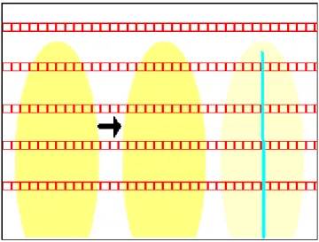
4.1.3 Number of Horizontal Lines Testing . . . 49
4.1.4 3D Pointer Mapping Testing . . . 50
4.1.5 Camera-Based Interaction vs. Keyboard Interaction Testing 52 4.2 Subjective Experiments . . . 55
4.3 Applications . . . 56
4.3.2 Application for Direct Manipulation . . . 57
4.4 General Discussion . . . 58
5 Conclusion 60 A Data 65 A.1 Quicksort . . . 65
A.2 Linear Regression . . . 66
A.3 Kalman Filter . . . 67
A.4 Mean . . . 68
A.4.1 Arithmetic Mean . . . 68
3.1 General Architecture of the System. . . 15
3.2 Architecture of Frame Sampling. . . 16
3.3 Working principle of Line Analyzer. - Red boxes are Color Blocks. 18
3.4 Working principle of Finger Tracking. . . 19
3.5 Color Block differences in the scene. - Green locations are Color Block differences. . . 22
3.6 Possible midpoints in the scene. Some of the Color Block differ-ences do not contain a possible midpoint . - Blue locations are possible midpoints. . . 25
3.7 Working principle of possible finger localization. . . 26
3.8 Possible finger in the scene. Kalman Filter and the window limit the possible location of the finger. - Light Blue line is the possible finger. . . 30
3.9 Working principle of Filtering. . . 32
3.10 Finger is moved from left to right in the image. Kalman Filter predicts that the new location of the finger will be at the right of the current finger location. . . 34
3.11 Arithmetic Mean calculates a more stable data out of noisy data. Light yellow fingers are tracked locations of the finger. Dark yellow finger is the calculated mean location of the two tracked finger
locations. . . 37
3.12 Filtered Finger’s received data from Filtering phase. . . 40
3.13 Working principle of Pointer Mapping. . . 40
3.14 New 5 DoF Pointer. . . 42
4.1 Test Environments. a)Night, living room, b)Midday, living room, c)Midday office. . . 45
4.2 Trajectory for translational motion (letter Z). . . 46
4.3 2D matrix click test. Blue circle is the target; green circle is the 2D pointer . . . 51
4.4 Direct manipulation test. User tries to put the 3D ball into the hole on the floor. . . 54
4.5 Example media application. . . 57
4.6 Example application for direct manipulation. . . 58
4.1 Properties of test environment . . . 44
4.2 RMSE table for Finger Tracking & Filtering Testing . . . 47
4.3 RMSE table for Stationary vs. Moving Background Testing . . . . 48
4.4 The system performance (in milliseconds) for stationary and mov-ing background for stages Fmov-inger Trackmov-ing(a), Filtermov-ing(b), and 3D Pointer Mapping(c). . . 49
4.5 RMSE table for Number of Lines Testing . . . 50
4.6 Catches & Misses of the users . . . 52
4.7 Controlling options for keyboard interaction . . . 53
4.8 Catching times for both camera based and keyboard based . . . . 54
Introduction
Background
The main purpose of HCI is to improve the interaction between devices such as computers and the users. 50 years earlier, this concept was just through switches and punched cards to enter commands. Respond of the computer was simple. The output was given via lights or line printers. Following years, with the development in speed and memory of computers, much faster and much direct interaction be-came popular. Today, the interaction between human and computer is much more directly, effectively and rapidly related. Now we have mouse, keyboard, accelera-tion sensors and several interacaccelera-tion methods that can directly communicate with the computers enabling us to directly manipulate an object in computers. We even have speech communication, writing surfaces and several similar products. J. C. R. Licklider emphasizes the importance of the Man-Computer interaction as follows [19]:
“Man-computer symbiosis is an expected development in cooperative interaction between men and electronic computers. It will involve very close coupling between the human and the electronic members of the partner-ship. The main aims are 1) to let computers facilitate formulative thinking as they now facilitate the solution of formulated problems, and 2) to en-able men and computers to cooperate in making decisions and controlling
complex situations without inflexible dependence on predetermined pro-grams.”.
The technology that enables us to interact with the computers consists of two parts. The first part is the input devices used for interaction. The second part is the devices that enable us to see the effect of the interaction. Display technologies, especially 2D displays, have matured to the level that further improvements are perceptually negligible. Recently, 3D displays are gaining popularity. A variety of 3D display technologies, such as auto stereoscopic displays, have emerged in the marketplace. These 3D displays are also being introduced on mobile devices (3DPHONE). These new modes of immersive interaction necessitate 3D input modalities for mobile use.
Motivation
In this thesis, we aim to provide a new mode of input for mobile devices featuring 3D displays. The currently available input techniques on mobile devices do not allow a rich level of interaction. A new level of user interaction is needed for 3D mobile use. However, these technologies are not used for new kind of mobile interaction and only a small number of new interaction techniques are developed using these new technologies. So a new and radical user interaction technique is necessary for the field.
Existing techniques do not address the real 3D and n-view screen interaction problem. There are few techniques for large displays but they are not suitable for mobile and moving small devices. Therefore a different solution should be provided to solve the human-computer-virtual object interaction problem. Some of the provided solutions use 2D input technologies to map 3D interaction and manipulate 3D objects virtually. As expected they cannot always handle the necessary movements of the objects in 3D space. Their input is limited and extra mapping is necessary. The first idea was to use mouse devices to map 3D interaction of 3D objects with 2D input [6]. Only a single plane is controlled with the 2D movement of mouse and the third degree of freedom is simulated with buttons on mouse. This is not suitable since this kind of approaches cannot
map direct manipulation situations. The second approach to solve the problem is to create a new 3D input, and several studies have been carried [9]. One of them is using acceleration sensors. This solution also cannot be considered as successful since user needs to move the whole device in order to activate sensor. In this situation, view of the user is lost and again direct manipulation cases are not handled. Using the rear camera to gain ego motion was another method but this solution also suffered from the same problems that acceleration sensors need to deal. So, in the absence of a suitable design for direct 3D input, we studied a new and original solution for mobile direct 3D input method.
Interaction in 3D displays is also weak with the existing input methods. Pro-posed solutions above have their disadvantages. 2D input methods such as touch screen and mouse do not cover the 3 degrees of freedom. 3D input methods such as acceleration sensors or ego motion with camera suffer from view point change and losing of 3D view. For lenticular displays and similar view point dependent 3D screens, user has to look at the screen from a narrow angle. Thus for mobile usage, a new method is necessary and expressed problems are solved with the proposed input technique in this thesis.
Our Contribution
The first part of the research is finding and defining suitable vision techniques for finger detection, finger tracking and movement recognition. Investigated tech-niques can be summarized as follows:
• We have developed a new camera-based interaction technique based on 3d finger tracking o n mobile devices. The technique consists of two parts. The first part consists of detecting finger in front of the camera. The second part consists of tracking these objects and identifying which one is the possible finger.
• We have developed techniques to map the tracked finger motion to 5 DOF input and to use it for direct manipulation of 3D objects. Depth analysis is also done at this stage of the study.
Outline of the Thesis
• Chapter 2 presents a comprehensive investigation of the previous work on the topics of Finger Detection, Finger Tracking and Movement Analysis on Mobile Devices.
• In Chapter 3, our proposed system for 3D Finger Tracking and HCI tech-niques are explained in detail.
• Chapter 4 contains the results of an experimental evaluation of the proposed HCI system.
• Chapter 5 concludes the thesis with a summary of the current system and future directions for the improvements on this system.
Background
There are a number of studies that have been carried related to camera-based interaction. These studies are divided into subcategories and explained in detail in the following sections.
2.1
Camera-Based Interaction
Interaction with computers and mobile devices have been developed in parallel over the recent years. Since mobile devices are getting more and more ubiquitous, users tend to demand more specific and efficient interaction methods for them. Alternative input methods to keypads and touch screens are being investigated and some new techniques have recently emerged. Alternative solutions such as acceleration sensors and camera-based interaction are becoming popular with the development of larger screens and richer data on mobile devices.
Camera-based interaction can be divided into two parts when used as the input method on mobile devices. The first technique is to use the device as a pointer itself by using the ego motion of the mobile device. On the other hand, the camera can capture an object in front of it and use it as a pointing item. In both, camera-based interaction requires capturing images continuously, collecting information in the scenes, identifying motion, and using the data as an interaction method. As the primary interest of this thesis, we have investigated finger-based interaction on handheld devices.
2.1.1
Finger Detection
The majority of the recent approaches for mobile devices that perform finger, hand, or head tracking use mono camera. Mono camera gives enough flexibility for the two dimensional screens provided, but its use for 3D input needs to be investigated. Stereo camera based solutions generally are too complex for mobile platforms. Therefore, in this thesis, we have chosen to use a single camera input for camera-based interaction to decrease computational requirements.
Tracking, in general, is studied in two fields: ego motion and object motion. Studies about ego motion address the problem of moving whole device movement [12, 13]. On the other hand, object motion studies address the problem of de-tecting moving objects in front of the camera [10, 1]. However since the principle is similar, we discuss both topics below.
Detection can be categorized into two major parts. The first part is edge-feature detection and the second part is color-based detection. Both approaches are investigated in detail and related information is presented in the following sections. According to the implementation and testing, color based tracking is more suitable in the case of finger tracking since finger does not have remarkable edges or features.
Edge - Feature Detection Methods
Moving the mobile device is a promising solution for a camera-based user interface. Several studies have been carried using this approach. In edge-feature detection method, the camera is essentially used like an acceleration sensor. The aim is to use the input from the camera located at the back of the device. Image analysis techniques are used to find the differences between consequent images in the input stream, calculating the ego motion of the device.
A fundamental problem in the usability of mobile devices is their limited dis-play size. To enhance the usability of the screen, Hannuksela et al. [12] developed a novel user interface solution for mobile devices which enables the display to be controlled by the motion of the user’s hand. A feature-based approach is proposed for both detection and motion analysis. At each time, captured image is divided into N sub-regions and in each region an M by M block is chosen according to the richness of texture. At each frame, these sub-regions are compared according to their specific block. In this way, movement is analyzed and motion of the device is established.
Haro et al. [13] have created a system for user interaction on mobile devices, using the ego motion of the device. Their approach is based on tracking corner-like features in the incoming camera images. The detected direction is used as the scroll direction in the application, and the magnitude is used to set the zoom level. The camera is treated as a pointing device and zoom level control in applications. Their tracker uses the current and previous frame captured by the camera. Corner like features are detected in the current frame which are matched with the features found in the previous frame. Direction estimates are accumulated for a number of frames before a movement direction estimate is made
A different study by Bucolo et al. [2] has a similar approach. Their study mainly focuses on identifying the similarities and differences between standard mobile phone joystick and a phone camera. The study results indicate that the joystick control provided the fastest completion times for each game, but with the lowest levels of user engagement.
Finger tracking is similar to tracking of mobile device movement. The main difference is that in this approach the features to be detected should be in front of the mobile device and the relative motion with respect to the mobile device is tracked. Therefore, by tracking the finger, it is possible to simulate the mouse or other UI item in the mobile device for the finger. There are several studies in the image analysis field for the topic but there has not been any complete user interaction system.
Hannuksela’s studies [10], [11] are good examples of what can be done with finger tracking as the user interaction method. In the first study they have introduced a new vision based interaction technique. According to this, the user moves his finger in front of the camera and the system tracks his hand movements. In this study, Kalman filter and Expectation Maximization algorithms are used. In the second study [11] they used a method that consists of two distinct motion components corresponding to the camera motion and the finger motion. They use hands, without markers, as the source of the motion for event creation. In this method one can directly interact with the objects in the system.
Color-Based Detection Methods
Color based detection can be investigated in two parts. These parts are di-vided according to their color space. HSV based and RGB based methods are both investigated.
In a study carried by Bulbul et al. [3], an HSV based face tracking approach has been proposed for mobile devices. This study was basically done for mobile devices. They used the advantage of homogeneity of hue values among different people faces. They scan continuous images to detect face in two general phases. These phases are clipping and face localization. Clipping is used to accelerate the process by only scanning the most probable window that will have the face of the captured image. Face localization has its own inner phases and generally uses HSV and smoothness properties of face. According to this study, color based tracking on mobile devices is fast and reliable. As the result of the study, camera based tracking can be used to control view point of 3D applications.
A primary approach for RGB based detection with camera is based on using markers. There are several studies and developed products that use markers. Markers can also give a good contrast with the background if chosen carefully but of course it has side effects like mobility problem. Johnny Chung Lee created [18] created a system that uses markers. He uses infrared cameras for the purpose. However a similar technique can be used in a 3D mobile device environment. Using a tracker gives several opportunities - e.g. understanding the position and orientation of the finger is easier. This creates a target for the camera to track.
Using a wearable tracker designed carefully like RGB-color code still may give good opportunities. Hachet et al. [9] introduced an RGB-color code camera-based user interface. The authors propose a new 3-DOF interface adapted to the characteristics of handheld computers. They designed a binary RGB-color coded flat background for the mobile device. Then by moving the background at the back of the device, they obtain the camera motion by using the trackers. They also can get depth from the system by analyzing the distance in-between the code pattern.
Predefined specific targets gives enough information about the target in marker based solutions. Chehimi et al. [4] created a game using mobile phone camera. In this work, the system can understand a predefined specific target cap-tured by the camera. The game uses specially designed colored tags, which are worn by the players, and advanced color tracking software running on a camera phone, to create a novel first person shoot-em-up (FPS) with innovative game interactions and play. Chehimi et al. report that they were able to code the target for special purposes. This can be used to solve limited input problem for mobile devices while dealing with camera based input techniques.
Another predefined specific target is CyberCode. It is similar to the previous study but this approach uses only black and white for coding. Rekimoto and Ayatsuka [20] created this approach, where real world objects in the system are defined by tagging them with barcodes. As each object has a code, camera detects this code and decodes it for further interaction. He uses CyberCode, a new technique for coding the real world objects.
2.1.2
Finger Tracking
Several research studies have been presented for head, hand tracking, particularly for desktop platforms. To the best of our knowledge, very few studies have been done on finger tracking on mobile devices. Related work can be divided into three categories: edge-feature tracking, color-based tracking and region tracking.
Edge-Feature Tracking
Hannuksela’s study explained above in [10] is the first major approach to solve the finger tracking problem on mobile devices. The approach makes use of Kalman Filter and Expectation Maximization for tracking purposes resulting an efficient and reliable tracking. Please refer Section 2.1.1 of this document for more information.
A study for desktop computers uses edge-feature based tracking for mouse like interaction. The study, “Camera Mouse”, is presented by Betke et al. [1], and it tracks user’s movements as the source for mouse. It directly extracts the movements of the user from a webcam etc. and uses the data to simulate the motion as the mouse pointer. This study is primarily for desktop computers but can be adapted to mobile devices as well.
Color Based Tracking
Color-based tracking of hands and face is investigated in Imagawa et al.’s study [15]. They have presented a real-time hand-tracking system for sign lan-guage recognition. According to their study, they create a hue-saturation map for the skin color by obtaining multiple samples of skin from images of several individuals under varying illumination conditions. By using the map, the system extracts the face and hand regions using their skin colors, computes blobs, and then tracks the location of each hand using a Kalman Filter. They differentiate the hands and head by focusing on the fact that the face does not move as much as the hand during sign-language motion.
Rohs and Zweifel [21] use CyberCode [20] to interact with real world objects. In their approach, they use visual codes to interact objects such as vending ma-chines or tram stops. This way they can learn when the next vehicle comes or similar information with the help of their mobile device. The mobile device cap-tures the image which contains the CyberCode and processes the it to receive necessary information. They also use the CyberCode to track the movement of the phone. The movement of the phone is transferred to the interaction engine and mapped to a virtual interaction method. With this method they can point, rotate, tilt, stay and interact in many different ways with the objects.
Region Tracking
Fieguth and Terzopoulos carried a study [8] on object, especially head, track-ing. Instead of edge tracking, a color cue is generated at each scene. Average color of pixels is stored in a specific region. The center of the region is searched in the following scene. Nearest locations are searched to keep working at around 30 fps. Each time nine points are searched in the scene.
A new algorithm called Projection Shift Analysis is used [7] in Drab and Artner’s study for motion detection. Their method calculates both x and y projections of all luminance values of each row and column. At each time, a difference factor is calculated according to the neighboring shift projections of the previous and current scenes. The smallest difference means the most suitable motion place.
2.2
Handheld Interaction
2.2.1
Single-Handed Mobile Device Interaction
Karlson et al. [17] have studied the use of one-handed mobile devices. Instead of working on specific technologies or specific tasks, they have focused on human factors and usability in one-handed mobile interaction. First they have completed a field study to gather the usage information of mobile phones or PDAs. Then they have prepared a survey. Participants answered questions about one-handed and two-handed mobile device usage in this survey. Finally according to these studies they have completed a thumb movement study. They have used tapping as the primary action and created an easy-hard region map according to the received information.
Another study carried by Karlson and Bederson [16] shows that thumb is best used in a portion of the touch screen. According to this, the user can only reach a part of the screen easily. The remaining part of the screen, which is not reachable by the thumb, is generally not used for interaction. Thus, to enhance usability, they allow the used portion of the screen to control the whole user interface. They have designed ThumbSpace and let the user interact with the screen inside a defined area. This method maps the area where the user interacts, to the whole screen space.
Other studies attempt the accuracy of finger interaction in the screen space. Dearman et al. [5]’s approach subdivides the screen space recursively for the accurate control of pointer, driven by the user’s finger.
2.2.2
Direct Manipulation Interaction
Decle and Hachet completed a study [6] which enables the 2D touch screen to be used as a 3D interaction method. They have worked primarily on thumb interaction on 3D objects. They used the screen as a trackball and manipulated a 3D object on 2D screen. In their study, horizontal movements produced rotation around up-down vector and vertical movements produced rotation around right-left vector. They have created a test application to accomplish a movement task to see the efficiency. They have investigated Direct Control vs. Planned Control with an experiment. According to the experiment, subjects were faster with the Direct Control than with the Planned Control.
As the literature survey indicates, there is a lack of comprehensive and com-plete 3D mobile human-computer interaction technique for 3D content and 3D screens. The current solutions are limited, as they are not mobile, they do not provide several degree of freedom, or they are suitable for use with 3D screens. Some of the techniques given above [9, 2] decrease the mobility, while others [10, 7] are computationally costly and inefficient. Some of these techniques [8] only address part of the problem, e.g. detection and tracking. Hence, there is a need for a complete 3D mobile interaction technique for 3D screens of handheld devices.
Camera-based Mobile 3D Input
In this work a method for 3D interaction on mobile devices is proposed. The system is fed by raw camera frame that is captured image from the front camera and is used as the basis for interaction with objects and the manipulation of data to create a 3D interaction system which is controlled by the movements of the finger in front of the camera. The interaction is as follows: The user moves his thumb in front of the camera to interact with the system. The system detects the finger and tracks movement of the finger to simulate the 3D interaction in virtual environment where the object to be manipulated is. This method can be used as direct manipulation or gestures can be created to command complex features.
3.1
General Architecture
The overall system consists of several stages. The first stage is detection and tracking of the finger. After that, a 3D pointer is mapped from the obtained position and movement data. The inner parts of the system are divided into subsystems as follows:
• Finger detection
• Finger tracking
• Mapping and control of the pointer for 3D mobile devices based on the filtered finger movement
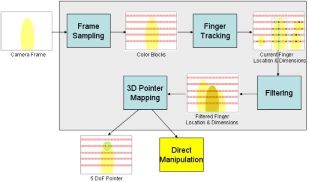
Figure 3.1: General Architecture of the System.
The general architecture of the 3D mobile interaction system can be seen in Figure 3.1. In this system, camera frame is used as the source. Our color based tracker tracks the finger motion. Color-based movement data is translated to a low-level motion data. Details of the methods that are used can be found in Chapter 2.
3.2
Frame Sampling
The first stage of our algorithm is reading front camera frames of the mobile device and using it as primary input for finger tracking as shown in Figure 3.1. The purpose of this stage is to gather necessary information from the camera and sample it for further use in the detection stage. At the end of this stage, the scene is divided into smaller color blocks to decrease the calculation complexity which makes the proposed method usable for mobile devices. The general architecture of this stage is shown in Figure 3.2.
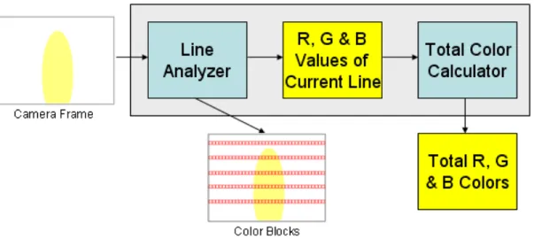
Figure 3.2: Architecture of Frame Sampling.
The only input of the system is raw camera frame. Data is provided in RGB color format. Each pixel’s RGB values are stored in a data element for later use. Once the pixel array is obtained, the system picks variable number of horizontal lines with constant distance between them according to the user’s specification on the line number. These lines are used for sampling purposes according to the systematic sampling principles. Each line, then, is divided into 64 pieces horizontally to distinguish the movement of the finger in x-axis. This enables us to complete lesser computation in the future stages.
The Purpose of Sampling?
In statistics, sampling is used when there is large data and limited computa-tional power. Usage of sampling provides small data which represents the general structure of the main data. In our case, the distribution of the data is fairly even, thus we have used nonprobability sampling which provides general distribution of all the RGB values in a horizontal line. Similarly systematic sampling [14] was chosen to represent the data for the same reason above. In order to generalize the approach, general sampling theorem (Eq. 3.1) is used. s(t) is the sampled set of pixels in the current line where δ is horizontal pixels set in the same line, n is the number of samples and T is the difference between them in pixels(sampling interval). s(t) = 64 X n=0 δ(t − nT ) (3.1) Line Analyzer
In the Line Analyzer of the system, RGB pixel array is traversed once to collect R, G and B values separately. The Line Analyzer starts from the leftmost pixel of a specific line. For each pixel on the line, it calculates sum of the upper and the lower 5 pixels vertically. This gives us the total of 10 pixels vertically which enable averaging of these 10 pixels. This process reduces single pixel noise of the system. As a result of this averaging step, we gather 640 pixel(which is the resolution of the captured image for width) color data for R, G and B values since the system adds each value individually to corresponding R, G or B data. When this is completed, the system starts adding 10 contiguous pixel data horizontally. We call this 10X10 pixel addition values a “Color Block”. This step is again done for R, G and B values separately. Each Color Block is put into an array location in a 64-element array of R, G, B Color Blocks. At the end of Line Analysis stage, we have obtained a horizontally analyzed line which is the sampling of total scene in 10 pixels selection. This scan is done for all horizontal lines in the scene and finally we get arrays of Color Blocks. The number of these arrays is the number of horizontal lines selected by the user. Illustration of Line Analyzer is given in Figure 3.3:
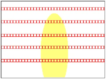
Figure 3.3: Working principle of Line Analyzer. - Red boxes are Color Blocks.
Total Color Calculator for Horizontal Line
During analysis of the scene in the previous part, we also add all the R values, G values and B values together to get the total of R, G and B values for each pixel in a line including 5 upper and 5 lower pixels. Once we get this we store it for further use. This data is used while the system is differencing the Color Block differences in a horizontal line of the scene. If the amount of light is high in the environment then the total value is large otherwise total value is small. With the help of Total Color Calculator, we can get the Color Block differences in the scene independent of the environment light density. This part is explained in Section 3.3.1 of this document.
3.3
Finger Tracking
Once we have obtained the Color Blocks of the scene, we can pass to Finger Tracking phase. Finger Tracking phase is one of the most detailed and challeng-ing phases in the overall system. There are several challenges in this stage. First of all, the system has to analyze the produced arrays of Color Blocks for possible midpoint locations of the finger in the scene. Secondly, the system has to distin-guish between noises and possible fingers in the scene. Finally, the system has to identify the borders of the finger. Among all these, the system has to get feedback from the filtering mechanism and has to search the finger in the provided area. Details of the Finger Tracking phase can be seen in Figure 3.4.
Figure 3.4: Working principle of Finger Tracking.
As shown in Figure 3.4, Finger Tracking has a number of steps. According to this, Finger Tracker gets Color Blocks as input from Line Analyzer. Another input for this stage is the Kalman Predict that is received from the Filtering stage. The output of the system is possible finger which is not post-processed. The result is used in Filtering mechanism as an input to filter the tracked finger. Tracked finger is determined in 3 dimensions.
Finger Tracking phase is completed in 3 consecutive steps. The first two steps are applied to all of the horizontal lines that are analyzed in the previous steps. The final step is applied to the result of the first two steps told above. These steps are “Color Block Differencing”, “Possibility Detection” and “Possible Finger Localization” respectively. According to this, each line that is analyzed in the previous steps is examined again to determine the Color Block difference locations in them. Once the Color Block difference locations in the respective line are determined, it is time to examine the Color Block difference locations and decide whether these differences contain a possible midpoint location. These two steps are repeated for all the horizontal lines in the scene. Finally by using the results of these two steps, the system tries to find a possible finger location in the scene by looking at the possible midpoint locations in each line. Detailed descriptions of these steps are explained below.
3.3.1
Color Block Differencing
Searching for Color Block differences is the primary stage in the Finger Tracking process. The input for this stage is the Color Block arrays of the horizontal lines individually. The result is another array containing the Color Block difference locations of the input line. Color Block difference locations are determined ac-cording to the R, G and B values of each Color Block. The system also uses the Total Color array to determine the Color Block differences. Total Color array for each line is calculated individually to discard the bad effects of the environmental light. Algorithm for Color Block Differencing is given in Algorithm 1:
Algorithm 1 The Algorithm for color difference identification.
1. new array differences [64] 2. for each color block
2.1. if current color block’s R value - next block’s R value is bigger than total color array’s R value of this line
2.1.1. if current color block’s G value - next block’s G value is bigger than total color array’s G value of this line 2.1.1.1. if current color block’s B value - next block’s
B value is bigger than total color array’s B value of this line
2.1.1.1.1. add this block to differences array
Color Block Differencing phase is applied to every line in the scene. This technique is applied as many as the number of horizontal lines, once for each line. For every line, the system creates a new array for 64 values since there are 64 Color Blocks in each line and each of them can be different than the consecutive Color Block. So, for each Color Block, starting from the leftmost Color Block, the system looks at the next Color Block and compares their R, G and B values one by one. If any of R, G, B values differ by a factor between two consecutive Color Blocks, the system sets the current Color Block as a Color Block difference location. Since color difference changes according to the color density of the current light of the scene, the difference factor between two consecutive Color Blocks has to be dependent on the current environmental light. Thus, to understand the color and light density, for each scene, the system keeps track of the summed R, G and B values of each Color Block for the current line. The system starts from the leftmost Color Block and calculates the color difference between the current Color Block and the right adjacent Color Block to it. The differences are calculated for R, G and B values separately for these two adjacent Color Blocks. These differences are compared to the total array values of R, G and B of that line. Before comparing the differences to total color values, the system divides the total color values by 640x10 since all the pixels are added together in each Color Block and only the average of them is needed. If current difference is larger than the total color then the system sets that location as a Color Block difference location and puts that location into a new Color Block difference array. An example of Color Block differences is shown in Figure 3.5.
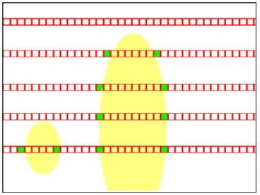
Figure 3.5: Color Block differences in the scene. - Green locations are Color Block differences.
3.3.2
Possibility Detection
Color Block differences in each line provide several possibilities for the finger. Although there are several possibilities, not every single one represents a possible finger location. To be a finger, a Color Block difference location has to have a number of properties. These properties are; sufficient distance between two difference points in the same line, vertical continuity of the finger, and a few more similar properties which are explained in the following sections. To determine the possibilities in each line, the system takes Color Block differences array as input. At the end of this process, a possibility midpoints array is created and given as output to the Possible Finger Localization stage. Possibility Detection process is illustrated in Algorithm 2.
Algorithm 2 The Algorithm for Possibility Detection in line.
1. new array possibilities [64]
2. for each difference location in differences array
2.1. if current difference location - next difference location is bigger than 9
2.1.1. checkPoint1R =0, checkPoint1G =0, checkPoint1B =0 2.1.2. checkPoint2R =0, checkPoint2G =0, checkPoint2B =0 2.1.3. for 10 pixels above and below the current midpoint
of 2 consecutive difference locations
2.1.3.1. checkPoint1R += pixelArray[midpoint of current and next difference location + current loops line number].R
2.1.3.2. checkPoint1G += pixelArray[midpoint of current and next difference location + current loops line number].G
2.1.3.3. checkPoint1B += pixelArray[midpoint of current and next difference location + current loops line number].B
2.1.3.4. checkPoint2R += pixelArray[midpoint of current and next difference location + current loops line number + 40 pixels down].R
2.1.3.5. checkPoint2G += pixelArray[midpoint of current and next difference location + current loops line number + 40 pixels down].G
2.1.3.6. checkPoint2B += pixelArray[midpoint of current and next difference location + current loops line number + 40 pixels down].B
2.1.4. checkPoint1R /= 20 2.1.5. checkPoint1G /= 20 2.1.6. checkPoint1B /= 20 2.1.7. checkPoint2R /= 20 2.1.8. checkPoint2G /= 20 2.1.9. checkPoint2B /= 20
2.1.10. if checkPoint2R - checkPoint1R is smaller than total array’s R
2.1.10.1. if checkPoint2G - checkPoint1G is smaller than total array’s G
2.1.10.1.1. if checkPoint2B - checkPoint1B is smaller than total array’s B 2.1.10.1.1.1. add this block to
possibilities array 2.1.10.1.1.2. add distance between
two difference points to possibilities array
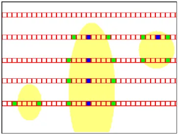
Possibility Detection phase is applied to every line in the scene. This technique is applied as many as the number of horizontal lines, once for each line. Since there are 64 Color Blocks in each line and the possible finger’s smallest width is accepted as 9, the highest number of possible midpoints in each line can be 64/9. Thus for every line, the system creates a new array for 16 values to put the possible midpoints. Two memory locations are reserved for each possible midpoint since one is used for location of the possible midpoint and the other is used for the distance between the Color Block difference locations. So, for each Color Block difference location in the Color Block difference array, the system looks at the next Color Blok difference location and compares these two locations according to the distance between them. If the distance is larger than or equal to 9, the system checks these two Color Block difference locations for more stability. The distance, 9, is defined by experience to limit the distance of the finger to the camera. Physically, if finger is too far away from the camera that a person cannot hold in one hand, then finger becomes smaller than 9 Color Blocks in length horizontally. After eliminating smaller noises from the scene, the system checks the determined Color Block differences again for color continuity. According to this, the system finds the midpoint of the two consecutive difference location that are candidates to be a possibility’s boundary points, and looks at the R, G and B values there. To eliminate the point pixel noise, the system adds 20 pixels’ color values from above and below the current midpoints pixel location and divides the result by 20 to get the average for 20 pixels. The same averaging is done 40 pixels below the current midpoint possibility location and two results are compared according to their average values. This process is done for R, G and B values. If the difference is not larger than the total color array of the current line then this means that there is continuity below the current point resulting that the current midpoint can be a possible midpoint for the possible finger for this line. This search is done for all Color Block difference locations in every horizontal line. The result here represents that if there is a possible finger in the scene, then, it has to have continuity all the way through the bottom of the image. At the end of this stage, possible midpoints are stored in an array with the locations of possible midpoints and the length of these possible midpoints. An example for detected possible midpoints is shown in Figure 3.6.
Figure 3.6: Possible midpoints in the scene. Some of the Color Block differences do not contain a possible midpoint . - Blue locations are possible midpoints.
3.3.3
Possible Finger Localization
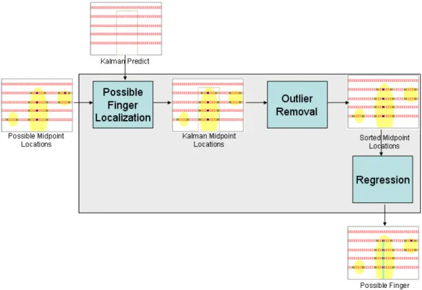
Possible Finger Localization depends on the results of possible midpoints that are gathered from the horizontal lines in the previous stage. The input of the system is the possible midpoints of the horizontal lines. The result of each line’s possibility detection is sent to the possible finger localization mechanism. One other input of the system is the Kalman Predict value which is calculated in the Filtering phase and provided to the Finger Tracking unit for possible finger localization. The output of the system is the possible finger that is determined by the series of algorithms applied above. Regression algorithm (Appendix A.2) is applied to calculate the line of best fit for the gathered midpoint cloud. Upper and lower midpoints of the finger, corresponding length values of the finger and y coordinate of the finger is provided as the result of this step and put into a new array. General architecture of Possible Finger Localization is provided in Figure 3.7.
Figure 3.7: Working principle of possible finger localization.
Possible finger localization is the last step of Finger Tracking phase. In this step, data collected from the previous stages are used with the help of feedback mechanism from the Filtering phase. Calculated possible midpoints in the pre-vious stages are taken as input and every possible midpoint in the array of each line is copied into one big array of possible midpoints. While copying these pos-sible midpoints into the big array, every pospos-sible midpoint is compared with the Kalman Predict which is obtained from the Filtering phase (details of usage of Kalman Filter is explained in the Section 3.4.1 of this document). If the possi-ble midpoint lies between the limits of Kalman Predict and the current window around it, then this possible midpoint is copied into the big possible midpoint array. The limits are also defined as a window. Initially the window is 16 Color Blocks. This window is shortened by one for every time there is a correct match. The system keeps shortening the window that is used with Kalman Filter until the window is bigger than 5. If the system is unable to find a possible finger in the limits of the current window, then the window is again widened to 16 Color
Blocks. This process is repeated for each line during the copying process. Once all the possible midpoints are copied into the big array of possible midpoints that is created at the beginning of the execution, the system sorts every possi-ble midpoint according to their horizontal location. This step is necessary since different possible midpoint values are present for different lines including noises in the scene. Sorting is done using Quicksort algorithm (Details of the Quicksort algorithm is provided in the Appendix A.1). Since Quicksort works in O(logn) in
average, time complexity is very low making it usable for mobile devices. After sorting the possible midpoints, system decides the longest continuous consecutive number block as the possible finger midpoint cloud. Algorithm for determining the possible midpoint cloud is provided in Algorithm 3:
Algorithm 3 The Algorithm for dividing the possible midpoint array into clus-ters and finding the longest possible midpoint sequence.
1. curCount = 1, maxCount = 0, maxStart = 0, maxEnd = -1, curStart = 0 2. for every item in the possibilities array
2.1. if current possibility location’s x value - next possibility location’s x value is smaller than 5
2.1.1. curCount = curCount + 1 2.2. else
2.2.1. if curCount is bigger than or equal to maxCount 2.2.1.1. maxCount = curCount
2.2.1.2. maxStart = curStart
2.2.1.3. maxEnd = current loop variable 2.2.2. curCount = 1
2.2.3. curStart = current loop variable + 1 3. if curCount is bigger than maxCount
3.1. maxCount = curCount 3.2. maxStart = curStart
3.3. maxEnd = current loop variable 3.4. curCount = 1
4. copy contents of old array to a new array from maxStart to maxEnd
While copying all possible midpoints and possible fingers, the system also keeps track of length of the Color Block differences which will allow the iden-tification of depth value in the further stages. Also maximum y value of the identified possible midpoint sequence is stored to understand the location of the finger in y direction at pointer creation stage.
As mentioned before, some extra techniques are applied to the captured image to clear the noise and get more stable results. To understand the vertical con-tinuity, the last possible midpoint array that is created after the previous stage is sorted again for the y locations of the possible midpoint values. Vertical con-tinuity is important since any possible noise detected may not be going through all the way down to the end of the screen. Thus any item that is not a possible finger because it is not continuous through the lower end of the scene is elimi-nated before it is behaved as a possible finger. Again Quicksort is used for the same reason explained above. This time sorted array is examined for its vertical continuity. This is done by the method in Algorithm 4.
Algorithm 4 The Algorithm for searching for the continuity in the finger’s ver-tical line numbers.
1. curCount = 1, maxCount = 0, maxStart = 0, maxEnd = -1, curStart = 0 2. for every item in the possibilities array
2.1. if current possibility location’s y value - next possibility location’s y value is smaller than 3
2.1.1. curCount = curCount + 1 2.2. else
2.2.1. if curCount is bigger than or equal to maxCount 2.2.1.1. maxCount = curCount
2.2.1.2. maxStart = curStart
2.2.1.3. maxEnd = current loop variable 2.2.2. curCount = 1
2.2.3. curStart = current loop variable + 1 3. if curCount is bigger than maxCount
3.1. maxCount = curCount 3.2. maxStart = curStart
3.3. maxEnd = current loop variable 3.4. curCount = 1
The array obtained from this stage is guaranteed to have vertical continuity and horizontal continuity at the same time. It is also guaranteed to be the best possible alternative in the provided Kalman Predict window. One extra check is completed after the above algorithm to enhance the stability and correctness of finding the possible finger in the scene. According to this last check, consecutive possible midpoint locations are compared according to their color values in R, G and B. A similar algorithm to Algorithm 2 is applied at this step and check points are compared to each other repeatedly. If there is a discontinuity in the finger, that possible midpoint location is set as the upper end point of the finger.
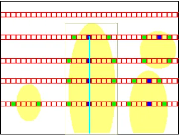
When all the above checking and comparisons are completed, the system moves to the next step and determines the possible finger. The possible mid-points in the scene are kind of a possibility cloud and a line of best fit has to be created out of those point data. The most suitable algorithm to be used in such a situation is Regression algorithm for line of best fit. It calculates the best line for the provided point cloud (Details of the regression algorithm are provided in the Appendix A.2). After applying the Regression algorithm, the system ob-tains a line equation. By using this equation and end points of the finger, the system creates the x coordinates of the beginning and end points of the finger. y coordinate of the finger is chosen as the upper end point of the finger and is already present in the system until the detection of the end points of the finger is completed. The width of the finger is also kept for further depth analysis and the width is obtained from the distance between the two sides of the finger for the upper end and the lower end separately. The final step only consists of calculat-ing and copycalculat-ing of these values into a new array and givcalculat-ing the data to Filtercalculat-ing phase. An example for localized possible finger is shown in Figure 3.8.
Figure 3.8: Possible finger in the scene. Kalman Filter and the window limit the possible location of the finger. - Light Blue line is the possible finger.
At the end, the system creates a line equation (Eq. A.1) that linear data has to fit.
y = mx + b (3.2)
x is the x -coordinate. y is the y coordinate. xi is the x value for i ’th data
point which is the each possible midpoint location’s x -coordinate. yi is the y
value for the i ’th data point which is the respective possible midpoint location’s y coordinate. N is the number of midpoints that are used. yave is the average
of the y values for the midpoints. xave is the average of the x values for the
midpoints. Equations from Eq. A.2 to Eq. 3.7 give the mathematical description of the model. Calculate sums: sxy = X (xi· yi) − ( P xi·Pyi N ) (3.3) syy = X (yi)2− [ (P yi)2 N ] (3.4) sxx = X (xi)2− [ (P xi)2 N ] (3.5)
Calculate Slope and Intercept: m = sxy sxx (3.6) b = yave− (m · xave) (3.7)
3.4
Filtering
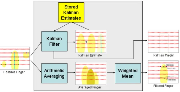
Filtering phase is used to filter the tracked finger in the consecutive images as the name indicates. Filtering phase has its own problems just like Finger Tracking phase. In this phase several techniques are applied, including Kalman Filter, arithmetic averaging and weighted mean to the tracked finger and as a result of these processes a much stable and reliable finger trajectory is created. The result of Kalman Filtering is used for estimating where the finger will be in the following frame. Kalman predict is sent back to the Finger Tracking stage for the next scene. Arithmetic averaging is applied on the current and past 3 movements to reduce the noisy data and create a more stable output on the current tracked finger data that comes from Finger Tracking phase. Weighted mean is applied on top of all the previous stages and used as a filtering method to overcome the flickering of the tracked finger. Details of the Filtering phase can be seen on Figure 3.9:
Filtering mechanism receives Possible Finger from Finger Tracker and that is the only input that comes to this phase. When the methods shown on Figure 3.9 are applied on Possible Finger that comes from Finger Tracking phase; Kalman Predict and Filtered Finger is produced as outputs by Filtering. Kalman Predict is used in Finger Tracking as explained before and Filtered Finger is used in the next phase which is 3D Pointer Mapping.
Figure 3.9: Working principle of Filtering.
In this stage the most important steps are averaging and weighting. Kalman Filtering is as important as the other processes carried in Filtering stage but it is primarily used in Finger Tracking stage instead of Filtering stage. Once the Possible Finger is generated by the Finger Tracking phase, Filtering starts to work and creates Filtered Finger out of Possible Finger. First of all Kalman Predict is calculated with the use of Possible Finger and stored predict values of Kalman Filter in the previous stages. After Kalman Predict is calculated, it is stored for next scene’s Finger Tracking process and sent to Finger Tracking when the next scene is captured. The next step in Filtering is Arithmetic Averaging. Since filtering requires previous stages of the flow, past locations of the finger are stored in Filtering mechanism. By using those values an arithmetic average mean is calculated and the result is sent to the weighted mean step. In weighted mean step, previous value of the Filtered Finger is weighted with the current result of averaged value of the finger. The result is the current Filtered Finger after this step. Detailed descriptions of these steps are explained below.
3.4.1
Estimation Using Kalman Filtering
Kalman Filter is implemented to estimate the location of the finger in the follow-ing frames. It provides estimation for the position of the ffollow-inger in the followfollow-ing image. The input is the current location of the finger which is Possible Finger received directly from the Finger Tracking and the previous stored estimate val-ues of Kalman Filter. A detailed description is found in this section for Kalman Filter, and the implemented algorithm is given in Algorithm 5:
Algorithm 5 The Algorithm for Kalman Filtering.
1. if this is the Kalman’s 3rd measurement value (measurement counter ) then reset variable
1.1. Pk = 1 1.2. Kk = 0
1.3. Xk = current location of finger 1.4. reset measurement counter
2. measurement counter = measurement counter +1 3. Kk = Pk / (Pk + 0.1)
4. Xk = Xk + Kk *(current location of the finger-Xk ) 5. Pk = (1.0-Kk )*Pk
6. Kalman Predict = Xk
Implementation of Kalman Filtering is a direct representation of the formula. The slight difference between implementing the Kalman Filter as it is and our implementation was to use 3 measurement values backwards instead of using a large number of backwards measurements. Going too much backwards is a good solution if we consider slow systems and much more stable data. Since our system is faster, more dynamic and the location of the finger is prone to change, we have chosen to track only 3 measurements backwards. Rest was the original algorithm for Kalman Filtering. Since Kalman Predict is one of the major prediction algorithms, the result was satisfying and the estimation of the finger location in the following scene was realistic. An image illustrating how the Kalman Filter predicts new location of the finger from the past movements is represented in Figure 3.10.
Figure 3.10: Finger is moved from left to right in the image. Kalman Filter predicts that the new location of the finger will be at the right of the current finger location.
Technical description of Kalman Filter can be shortened as follows (For a full description of Kalman Filter, please refer to Appendix A.3 of this document):
There are 3 steps in Kalman Filter. The first step is to build the model of the system. According to this, we have used Possible Finger (current location of the finger coming from Finger Tracking phase) as the signal value for the Kalman Filter. We used 0.1 as the process noise because it gave the best result after a series testing of values. The second step is to start the process. Starting the process is basically giving the equations their initial values which are the minimum values for the equations. When starting the process, time update and measurement update stages were reset to their initial states. Initial states for the values are as follows: Pk = 1, Kk = 0 and Xk = current location of the finger. The third step is the iteration step. Iteration step is repeating the process during the runtime. In this step, we continuously update our predict value and correct the predict value with the received values. Any time a scene is present, we calculated a prediction for the next scene’s finger location. Mathematical explanation of the Kalman Filter is as given in equations from Eq. A.5 to Eq. A.11. Here A is the state transition model which is applied to the previous state, B is the control-input model which is applied to the control vector uk , wk−1 is the process noise
Building a Model:
System has to fit the models below:
xk = A · xk−1+ B · uk+ wk−1 (3.8)
zk = H · xk+ vk (3.9)
Start the Process:
Time Update: ˆ x−k = A · ˆxk−1+ B · uk (3.10) Pk− = A · Pk−1· AT + Q (3.11) Measurement Update: Kk = Pk−· H T · (H · P− k · H T + R)−1 (3.12) ˆ xk = ˆx−k + Kk· (zk− H · ˆx−k) (3.13) Pk = (I − Kk· H) · Pk− (3.14) Iterate:
Repeat the equations from Eq. A.5 to Eq. A.11 for every time a new value has entered the system.
3.4.2
Arithmetic Average for Stabilization
Arithmetic averaging is applied on top of the Possible Finger. We have kept 3 previous locations of the finger. Adding the new location of the finger to those previous locations and taking the arithmetic mean of these locations provides a much more smooth transition between movements. By applying this method we have overcome the problem of sudden unwanted movements of the possible finger. This method decreases the bad effects of a miss in the detection of the finger. The disadvantage of using this step in Filtering phase is that when the finger moves into one direction, trajectory of the finger(filtered finger) is close to the previous locations of the finger. The storing of the previous locations of the finger and applying arithmetic averaging is described in Algorithm 6:
Algorithm 6 The Algorithm for Storing Previous Locations of the Finger and Applying Arithmetic Mean.
0. define new array, Averaged Array , at the time of creation of the Filtering phase to store previous location of the finger
1. define new array Averaged Finger
2. for the length of the array, Averaged Array 2.1. Averaged Array [i] = Averaged Array [i+1]
3. put current location of the finger into last empty spot in Averaged Array
4. for the length of the array, Averaged Array 4.1. Averaged Finger [0] += Averaged Array [i]
5. Averaged Array [0] /= number of elements in array, Averaged Array
Arithmetic averaging implementation is composed of two stages as explained above in the algorithm. The first part consists of keeping track of previous loca-tions of the finger and the second part consists of taking the arithmetic average of the previous locations of the finger along with the current location of the finger. To keep track of the previous locations of the finger, the system creates a global array. So Averaged Array is created once and every iteration data is stored in it. Thus, every time when the execution comes to averaging stage, the system starts by moving the previous data one spot left in the array to create a location for the new element by dropping the first element of the array. After organizing the
previous locations and the current location of the finger, the system adds every item in the array together and puts the sum into a new array, Averaged Finger. By dividing the value in Averaged Array with the number of elements, 4 in our case, gives us the arithmetic mean of the past three locations of the finger and the current location of the finger. One notable thing here is that this process is done for all x, y and z locations of the finger. Arithmetic mean as Averaged Finger is represented with A in the following equation (Eq. A.12):
A := 1 n · n X i=1 · xi (3.15)
where n is 4 in our case since 3 previous locations and the current location is taken into consideration because of keeping the average close to the current lo-cation of the finger and x values are three past finger lolo-cations and the current finger location. Averaging keeps the location of the finger stable in the case of fail in detection or tracking. The effect of arithmetic averaging is illustrated in Figure 3.11.
Figure 3.11: Arithmetic Mean calculates a more stable data out of noisy data. Light yellow fingers are tracked locations of the finger. Dark yellow finger is the calculated mean location of the two tracked finger locations.
3.4.3
Weighted Mean for Flicker Filtering
As in the case of arithmetic averaging, taking weighted mean is used to create a more stable data from the detected finger. By using weighted mean, sudden jumps in the movements and unstable moving of the detection are avoided. There are two inputs for weighted mean. The first is the current averaged finger value and the second is the previous stored weighted location of the finger. The first one is received from the previous step in Filtering and the second one is stored in the system from the previous iteration. As a result, tracked finger is created and it is much more stable and constant than the possible finger. Details of the algorithm can be seen in Algorithm 7:
Algorithm 7 The Algorithm for Weighted Mean.
0. define new array, Stabilized Finger , at the time of creation of the Filtering phase to store previous weighted meaned location of finger 1. define new array Filtered Finger
2. Filtered Finger [0] =
(Normalized Finger [0]*weight ) + (Stabilized Finger [0]*(1-weight ))
3. Stabilized Finger [0] = Filtered Finger [0]
Weighted mean implementation is composed of two stages as explained above in the algorithm. The first part consists of calculating the weighted mean and the second part consists of keeping track of previous locations of the tracked finger. To keep track of the previous locations of the tracked finger, the system creates a global array. So Stabilized Finger is created once, and every iteration data is stored in it. Thus, every time when the execution comes to weighted mean stage, the system starts by calculating the weighted mean of the current location of the finger and previous location of the filtered finger. This calculation is done giving weight to both of the values so using values of the both values but at desired level. In our implementation we have chosen to give weights 0.9 and 0.1 to current location of the finger and previous location of the filtered finger respectively. This gave more weight to the current location and less weight to the previous location but both of them are used to distinguish the current location
of the filtered finger. When this calculation is completed, the system stores the current filtered finger location into the Filtered Finger array for the next scene use and this completes the filtering phase. Weighted mean is calculated with the following formula (Eq. A.13). (Details of weighted mean can be found in the Appendix A.4.2 section of this document)
ˆ x = Pn i=1wi· xi Pn i=1wi (3.16) Where, [x1, x2, . . . , xn] (3.17)
representing finger locations where n = 2 in our case and
[w1, w2, . . . , wn] (3.18)
representing weights that are assigned to the finger locations.
3.5
Handheld Interaction
At the end of Finger Tracking and Filtering phases, a stable filtered finger location is obtained. This data represents y location of the finger’s upper end on the screen along with the x location of that point. The (x, y) location of the finger’s lower end is also represented with this method. The distance between the two sides of the finger is also received from the previous stages. A representation of this data is given in Figure 3.12 below:
Figure 3.12: Filtered Finger’s received data from Filtering phase.
Handheld Interaction mechanism maps a pointer data from the filtered finger data. The output of this system is a global 5 DoF pointer data that can be used as a general pointer for every system. There are currently two steps in this stage and the number can be extended. The first step is to map a 5DoF pointer from the Filtered Finger data. In this step the data is converted into a usable pointer data. In the second step, the 5 DoF pointer data is converted to global coordinate system which enables the pointer to be used in any platform. Steps of Handheld Interaction can be seen in Figure 3.13.
Figure 3.13: Working principle of Pointer Mapping.
Filtered Finger is the only input of this stage. By using Filtered Finger, Pointer Mapping mechanism first maps a 5 DoF pointer. While mapping the 5 DoF pointer, x location of the upmost point in the finger is set as the x coordinate of the pointer. Similarly, y coordinate is set as the upmost point’s y location. z coordinate is set by using the distance between the two sides of the finger at location x, y. The other two DoF values are lean in x coordinate and lean in z
![[Nermidil Erner Binark'ın "Şakir Paşa Köşkü-Ahmet Bey ve Şakirleri" adlı kitabının tanıtım haberi]](data:image/gif;base64,R0lGODlhAQABAIAAAP///wAAACH5BAEAAAAALAAAAAABAAEAAAICRAEAOw==)