An Approach for Detecting Inconsistencies between
Behavioral Models of the Software Architecture and the Code
Selim Çıracı
1, Hasan Sözer
2, Bedir Tekinerdogan
3 1Pacific Northwest National Laboratory, Richland, WA, USA
[email protected]
2
Özye˘gin University, ˙Istanbul, Turkey
[email protected]
3Bilkent University, Ankara, Turkey
[email protected]
Abstract
In practice, inconsistencies between architectural docu-mentation and the code might arise due to improper imple-mentation of the architecture or the separate, uncontrolled evolution of the code. Several approaches have been pro-posed to detect inconsistencies between the architecture and the code but these tend to be limited for capturing inconsis-tencies that might occur at runtime. We present a runtime verification approach for detecting inconsistencies between the dynamic behavior of the documented architecture and the actual runtime behavior of the system. The approach is supported by a set of tools that implement the architecture and the code patterns in Prolog, and automatically gener-ate runtime monitors for detecting inconsistencies. We illus-trate the approach and the toolset for a Crisis Management System case study.
Keywords: Software architectures, Runtime verification, Inconsistency detection.
1
Introduction
Software architecture [4, 22] is one of the key artifacts in the software development lifecycle. It embodies the key de-sign decisions, gross-level components of the system, and interactions among these components. Hence, document-ing software architecture is important for guiddocument-ing the imple-mentation of the system and likewise supporting software maintenance and evolution [6]. In addition to implementing the structure imposed by the architecture, it is important to realize the dynamic behavior of the architecture. In prac-tice, inconsistencies between architectural documentation and the code might arise due to improper implementation of the architecture or the separate, uncontrolled evolution
of the code. The latter situation has been termed as archi-tectural drift [20, 18].
There have been numerous approaches proposed [23] to check the consistency of architecture documentation with respect to the implementation. Several approaches tend to be based on static analysis of the code [2] and do not exploit information that is collected at runtime. However, the exe-cution scenarios, as imposed by the behavioral models of the architecture, largely depend on the runtime interactions of the system with users and/or other systems. As such, in-consistencies between the architecture and the code might only become apparent at runtime. Static analysis techniques are also limited due to the fact that the set of execution scenarios defined by the behavioral models is usually un-bounded or is intractable to explore/check exhaustively.
In this paper, we propose a runtime verification ap-proach, ConArch for detecting inconsistencies of an ar-chitectural documentation with respect to the implemen-tation. There have been many runtime verification tech-niques proposed to monitor an operational system based on formal specifications (finite state machines, regular ex-pressions, temporal logic, etc.) [17]. However, verifica-tion specificaverifica-tions are usually defined manually, based on requirements and constraints, which are otherwise already documented in design models. In our work, we utilize exist-ing architectural behavior models as specifications for run-time verification. We automatically convert call patterns in the source code to Prolog facts. The user provides a map-ping from the design models to the source code in the form of Prolog rules. Our tools execute these rules and gener-ate a specification (a stgener-ate machine representation) together with runtime monitors (monitors for executing system). We utilize aspect-oriented development techniques [11] to in-strument the source code and integrate our runtime moni-tors. These monitors observe and report execution scenar-2012 IEEE 36th International Conference on Computer Software and Applications
0730-3157/12 $26.00 © 2012 IEEE DOI 10.1109/COMPSAC.2012.36
255
2012 IEEE 36th International Conference on Computer Software and Applications
0730-3157/12 $26.00 © 2012 IEEE DOI 10.1109/COMPSAC.2012.36
255
2012 IEEE 36th International Conference on Computer Software and Applications
0730-3157/12 $26.00 © 2012 IEEE DOI 10.1109/COMPSAC.2012.36
255
2012 IEEE 36th International Conference on Computer Software and Applications
0730-3157/12 $26.00 © 2012 IEEE DOI 10.1109/COMPSAC.2012.36
ios that conflict with the documented architecture design. We have applied our approach to the Crisis Management System (CMS) case study [15]. We have showed that our approach is effective in detecting inconsistencies between the architecture documentation and implementation, in par-ticular for interacting scenarios spanning multiple layers in a layered architecture. Furthermore, the approach is auto-mated by a set of integrated tools, which makes its applica-tion possible with limited manual effort.
The remainder of this paper is organized as follows. In the following section we present the case study that is used as a running example throughout the paper. In Section 3, we describe our overall approach. Then, we describe each step of the approach in detail from Section 4 to 7. In Section 8, we discuss our findings regarding the application of the approach on the case study. We summarize related studies in Section 9. Finally in Section 10, we provide conclusions and discuss future work.
2
Case Study: Crisis Management System
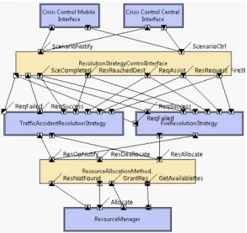
Crisis Management System (CMS) [15] is used for coor-dinating the crises resolutions. CMS receives reports about crises and, based on the type of the crisis, it dispatches re-sources (like police) to the scene. Once the report of a suc-cessful resolution of a crisis is received, CMS de-allocates the resources used for resolving this crisis so that they can be used for other crises. CMS views crisis resolution pro-cess as a state machine, whose transitions are the reports received from the scene. At each state, CMS executes cer-tain actions that would resolve the crisis or generate more reports. Depending on the type of the crisis, the executed actions differ. These actions are defined in programmable crisis managers called “Resolution Strategy Components”. Figure 1 presents the architecture design of CMS, which includes two of such resolution strategy componentsTraffi-cAccidentResolutionStrategy and FireResolutionStrategy;
in principle, there can be many such resolution strategy components.
CMS can be controlled from multiple sources called Clients. For example, the component Crisis Control
Cen-ter represents the user inCen-terface running at the
headquar-ters. The connector ResolutionStrategyControlInterface is the gateway between the clients and the resolution strategy components. It collects the reports from the clients and di-rects them to the appropriate resolution strategy component. It also sends notifications from the resolution strategy com-ponent to the appropriate clients.
The resolution strategy components are linked to the connector ResolutionStrategyControlInterface through ports dedicated for carrying different types of reports. For example, the port InitialCrisis caries the initial report about the crisis. The resolution strategy components send
re-Figure 1. The Component & Connector model of the Crisis Management System
source (de)allocation requests to the connector
ResourceAl-locationMethod. This connector queries the component ResourceManager to find the resources according to
cer-tain allocation strategies, such as first-come-first-serve or nearest-resource (i.e., resources closest to the scene). After finding the resources, ResourceAllocationMethod allocates them and notifies the resource resolution strategy compo-nent about the successful allocation.
In the design, the behavior of resolution strategy com-ponents in CMS is constrained by a state-machine; the resolution strategy components should react according to the state of the crisis and only respond to the reports that move the crisis resolution to the next state. An example of the state constraints is presented in Figure 2, depicting the actions executed by the component
TrafficAccidentRes-olutionStrategy when it receives a message from the port ResRequest. Messages from this port are sent after the
ini-tial information about the crisis is received to dispatch the resources.
From the figure, we can see that the component
Traffi-cAccidentResolutionStrategy can respond to this message
in two ways: if a previous request to allocate resources has failed, the scenario sends a failure message from the port
ReqFailed. If, on the other hand, the scenario has the initial
report (and this is the first request to allocate resources), the scenario sends a message about the desired resources to the connector ResourceAllocationStrategy. Finally, depending on the availability of resources, the component TrafficAc-256
256 256 258
Figure 2. Behavioral model showing the ac-tions executed by the component
TrafficAcci-dentResolutionStrategy
cidentResolutionStrategy can respond with a ReqFailed or ReqSuccess message.
As can be seen from this example, the state checks are crucial in efficient allocation of resources and flawless op-eration of the crisis resolution process. Every resolution strategy component should apply these checks and reply with appropriate messages to ensure correct operation of CMS. Therefore, architects need to verify that behavioral models, like the one in Figure 2, are correctly implemented. Also, evolution of the code should not hamper such design constraints after implementation. However, CMS might have many resolution strategy components such that checks cannot be realized manually by reviewing the source code. Moreover, behavioral models must be checked in the con-text of relevant execution scenarios of the system, which is highly dependent on user intervention in reactive systems such as CMS. Thus, automated verification at runtime is needed to assure the correct implementation of such behav-ioral models. In this paper, we present theConArch ap-proach that uses runtime verification to verify the consis-tency between behavioral models and the implementation.
3
Overview of ConArch
In runtime verification (RV), information about the exe-cuting software is extracted and verified against user spec-ified constraints [17]. This information, usually, contains the sequence of calls executed by the software system at
runtime. The constraints, on the hand, defined as desired or-ders of these calls specified using a formalism such as tem-poral logic. One of the issues with RV approaches is that the user has to re-specify the constraints that are otherwise specified in design models. With theConArch approach, we provide a process for utilizing architectural behavioral scenario models as specifications for RV.
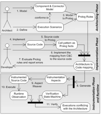
ConArch approach consists of activities that are carried out in three phases as shown in Figure 3. The activities at the first phase are carried out during the architecting phase. Here, the software architect models the component & con-nector (C&C) [6] diagrams describing the structure of the software system. In addition to this, the architect, with other stakeholders, defines execution scenarios depicting impor-tant behaviors of the software system. The defined scenar-ios are expressed with a scenario specification language (ex-plained in Section 4). The semantics of this language is similar to that of UML sequence diagrams. With the given scenario and the C&C models,ConArch toolset generates the specification to be verified at runtime and the signatures of Prolog rules for each interaction in the given scenario.
Since the architectural models (C&C and behavioral sce-nario models) are at a higher level of abstraction than the source code, the elements of these models (components, connectors, ports, and etc.) might not exist in the source code as they are specified. Therefore, we need to map the elements from the architecture models to the implementa-tion. InConArch, mapping is a semi-automated process: the tools generate the required programming interface (API) and the user implements the mapping using this API. In the first phase, signatures are generated for all the architectural elements that need to be mapped to the source code.
The activities of the second phase are carried out dur-ing the implementation. We implemented this phase of ConArch for source files written in Java and C++. In this phase, first the source code of the software system is placed into the call graph extractor tool ofConArch. This tool parses the source code, extracts the call graph and saves the call graph as a set of Prolog facts. These Prolog facts form the API that is used for implementing the mapping. Using these facts the software engineers implement the bodies of the rules whose signatures are generated from the behav-ioral scenario. In this way, the mapping from the architec-ture to the source code is established: querying for these rules would return the set of calls to which each interaction in the scenario maps.
Once the mapping is established, the activities in the third phase are carried out. Here, firstConArch generates the instrumentation aspects (in AspectJ and AspectC++ lan-guages) that will be used for monitoring the execution of the software system. These aspects intercept the calls that map to the interactions of the behavioral scenario and notify runtime verifier ofConArch. Using the mapping, ConArch
257 257 257 259
Figure 3. The Overall Approach
also generates the scenario specification. This is the formal specification that is used for verifying the execution. At run-time,ConArch verifier listens to the notifications from the instrumentation aspects and verifies that these are occurring in the order as they are specified in the behavioral scenario.
4
Modeling Behavioral Scenarios
We use Eclipse ArchStudio environment, based on the xADL language [9], for modeling the C&C diagrams. These diagrams document the runtime structure of the sys-tem. However, we also need to document the runtime be-havior of the system in the form of execution scenarios. Such a scenario is depicted in Figure 2 with a UML se-quence diagram. For our purposes, the documentation of execution scenarios should be i) formal, ii) aligned with the structural (C&C) diagrams, iii) editable within the in-tegrated tool environment, and iv) comprising all the con-cepts necessary for runtime verification. To fulfill these goals, we have designed a domain-specific language, and utilized TCS (Textual Concrete Syntax) [14] for defining a concrete syntax to attain the necessary and just enough ex-pressiveness. Based on this language, execution scenarios can be defined in alignment with the C&C diagrams, they can be edited with specialized editors as part of the Eclipse environment and resulting models can also be converted to Eclipse EMF [8] models. In the following, we describe the
Figure 4. An Example Execution Scenario
concrete syntax and semantics of this language.
An execution scenario is a sequence of interactions, each of which is defined as messages exchanged among ports of components in the C&C diagram. Interactions can be either synchronous (by default) or asynchronous (annotated with the async keyword). In addition, we have included the following concepts that define the control flow of interactions.
Alternative frame is a set of two sequences of inter-actions that constitute alternatives to each other. Depending on the system state, either of the two sequences is included in the execution scenario (analogous to if-then-else state-ment).
Optional frame is a sequence of interactions that can be included or excluded as a whole, depending on the system state (analogous to if statement).
Return interaction is a special type of interaction that represents the callback of a synchronous interaction.
Figure 4 shows a snippet from an execution scenario, corresponding to the upper part of Figure 2. Hereby, an
alternative frame is defined for the ResRequest port of
component TrafficAccidentResolutionStrategy. One of the alternative sequence of interactions become active in this frame based on a state of the system (i.e., whether the res-olution strategy has already failed or not) as specified in brackets (requestAlreadyFailed or hasInitialReport). The very first interaction of the execution scenario is annotated with the initial keyword.
Once behavioral scenarios are modeled, they are pro-vided toConArch, which converts these models to a behav-ioral execution automaton as described in the next section. 258
258 258 260
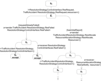
Figure 5. An excerpt from behavioral automa-ton generated from the scenario in Figure 2
5
The Behavioral Execution Automaton
Given a behavioral scenario, ConArch traces the sce-nario and generates a deterministic automaton, which we refer to as Behavioral Execution Automaton (BEA). BEA forms the basis specification that will be used byConArch runtime observer to verify whether the executing system follows the behavioral scenario. Each transition in BEA represents an interaction in the scenario. Below we describe trace semantics used for generating the BEA from the be-havioral scenario:• ConArch adds a start state S0and sets the current state (Scurrent) toS0. Then, it traces the first interaction in the scenario. In the scenario depicted in Figure 2, the first interaction is ResRequest(). An excerpt from the BEA for this scenario is depicted in Figure 5. Here, we can see that the outgoing transition from the start state (S0) corresponds to the first interaction of the scenario.
• For an interaction i < F.p1, T.p2 > (P ), where P
is the list of parameters passed to the interaction, F is
the component or the connector the interaction originates from, T is the receiver of the interaction, p1 and p2
are the corresponding ports, ConArch adds the transi-tioni < F.p1, T.p2 > (P ) from state Scurrent. It also
adds a stateSias the destination of the newly added
tran-sition and sets the current state toSi. Then,ConArch
starts tracing the first interaction that is executed byT in
response toi < F.p1, T.p2 > (P ). In Figure 5, the
inter-action ResRequest() is received by the component
Traf-ficAccidentResolutionStrategy, which executes an
alter-native frame in response to this interaction. In Figure 5,
the interaction ResRequest() is represented with the tran-sition from stateS0 toS1. The alternative frame that is executed by TrafficAccidentResolutionStrategy, is rep-resented with the two outgoing transitions from stateS1. • If the traced interaction is an alternative frame with n
operands,ConArch adds n outgoing transitions from the current state. Each of these transitions corresponds to the first interaction of each operand. Then,ConArch traces each of these interactions. For example, the transitions between statesS1-S2andS1-S5in Figure 5, corresponds the first interactions of operands of the first alternative frame in Figure 2.
• For a return interaction r < F.p1, T.p2 > (R), where R is the returned value, ConArch adds a new state Sr,
a transitionr < F.p1, T.p2 > (R) from ScurrenttoSr,
and sets the current state toSr.ConArch, then traces the
first interaction executed by the componentF after the
return interaction. In Figure 2, after executing the asyn-chronous interaction ResAllocateResources(), the com-ponent TrafficAccidentResolutionStrategy returns. This return interaction is shown with the transition between statesS2-S4.
• An asynchronous interaction a < F.p1, T.p2 > (P ) is
converted to two consecutive transitions. The first transi-tion designates the originator of the asynchronous inter-action and the second one designates the receiver of the interaction. After adding the first transition and the corre-sponding stateSa1,ConArch traces the interactions
ex-ecuted by the componentF following the asynchronous
interactiona. When all these interactions in component F are traced, ConArch returns to the state Sa1, adds
the second transition and traces the actions executed by componentT in response to the asynchronous interaction a. The asynchronous interaction ResFailed() in Figure 2
is represented with the transitions between statesS1-S2 andS2-S3. The first transition states that the component TrafficAccidentResolutionStrategy has initiated an
asyn-chronous interaction to the connector
ResolutionStrate-gyControlInterface. Note the two outgoing transitions
from stateS2. The transition to state S4 represents the return action the component
TrafficAccidentResolution-Strategy executes after initiating the asynchronous
inter-action. The transition to stateS3, on the other hand, states that connector ResolutionStrategyControlInterface has received the asynchronous interaction ResFailed(). The stateS3has no outgoing transitions, because the scenario in Figure 2 does not show any interactions executed by the connector ResolutionStrategyControlInterface in re-sponse to the interaction ResFailed().
Note thatConArch marks the states without any outgoing transitions as accept states.
259 259 259 261
5.1 Generating the Signatures of the Pro-log Rules for Mapping
An interaction can be implemented in many ways and, as such, manually implementing a monitor for each type of interaction is not practical. ConArch abstracts away the details of how an interaction is implemented and focuses on the activation of the ports during an interaction. Interactions are verified by observing three events. First, the port send-ing the message should be activated. Then, the port receiv-ing the message should be activated. Finally, in between these two events, the other ports should not be activated. At runtime, we can only observe the executions of the methods and the calls; hence, we need to represent these three events in terms of the execution of a set of methods and/or calls, or a sequence of calls. This is realized by mapping the ports to methods and calls in the implementation.
InConArch, we use Prolog as it has been proven suc-cessful in providing a similar mapping [19]. The mapping is realized in two steps, where the first step is executed when BEA is generated and the second step is executed once the implementation is ready (detailed in next section). The first step simply generates the signatures of the Prolog rules where the user implements the query for the mapping. These signatures are as follows:
port(nameport, namecomponent, List): generated for the ports of the interactions; in these rules, the user implements the mapping for the port of a component. condition(condition, M appedAttributesF rom, M appedAttributesT o): generated for each distinct condition of the interactions. Here, the user implements the Prolog rule that evaluates the condition (detailed in next section)
6
Mapping Implementation to the
Architec-tural Elements
In the second step of mapping (activity six of Figure 3), the user implements the mapping from ports to calls/meth-ods using facts representing the class structure and the call graph of the software system. This section details how ConArch converts the class structure and the call graph to Prolog facts and, then, presents how the mapping is imple-mented.
6.1 Representing source code elements as Prolog facts
We implemented a plug-in for Eclipse and a plug-in for the GNU C/C++ compiler to extract the class structure and the call graph from source files implemented in Java and C++. These tools traverse the syntax tree to recognize the class/method declarations and the call statements. For each
of these declarations and statements, we designed a corre-sponding predicate. Hence, when the plug-ins recognize a class/method declaration or a call statement in the syntax tree, they simply export the fact by initializing the predicate corresponding to the recognized statement. In the follow-ing, we list the predicates that correspond to the declarations and statements needed for the mapping.
• class(id, name): Represents a class declaration. id is a
unique integer identifier assigned by the plug-ins.name
represents the name of the class.
• superType(idsubtype, idsuperT ype): Represents the
inher-itance between two classes.
• primitiveType(id, name) and
structureType(-id, name): Represents primitive types, such as int, and
structure types.
• pointerType(id, idtype) and
referenceType(-id, idtype): Represents a pointer or a reference to the type
designated withidtype. Here,idtypecan be the identifier
of a primitive, class, or structure type.
• method(id, idclass, name): A method of the class
designated with idclass. For example, the fact
"method(3,1,’dispatch’).", represents the method dis-patch() of the class TrafficAccidentResolutionStrategy. • parameter(idmethod, idtype): A parameter of a method
designated withidmethod. Here,idtypecan be the
identi-fier of a pointer, a reference, a structure, a primitive or a class type.
• varDecl(id, idowner, idtype, name): Represents a
vari-able declaration. If the owner type is the identifier of a class, then it represents an attribute. On the other hand, if the owner is the identifier of a method, then it represents a variable declared in a method.
• addressOf(id, idvar), referenceOf(id, idvar): The
ad-dress or the reference of a variable.
• callState(id, idto, idf rom): A call to a method. For
ex-ample, the fact "callState(4,3,1)" represents a call to the method dispatch() of the class
TrafficAccidentResolu-tionStrategy.
• argument(idcall, idpass): Represents an argument of a
call.idpasscan be the identifier of a variable declaration
or an address/a reference of operator.
6.2 Mapping ports to source code
To generate the instrumentation aspects, ConArch queries the predicate port(<nameport>,
<namecompo-nent>, List) for each port it encounters in the BEA model.
260 260 260 262
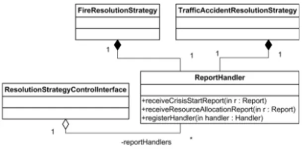
Figure 6. An excerpt from the design of CMS
In the third parameter, ConArch passes an empty list and expects the user implemented mapping to unify this parameter with the list of methods or calls a port maps to. To clarify the mapping, recall the interaction ResRequest in Figure 2. This interaction is carried out between two ports: ResolutionStrategyControlInterface.ResRequest
and TrafficAccidentResolutionStrategy.ResRquest. There-fore, we need to implement two Prolog rules to verify this interaction.
Assume that each resolution strategy is implemented by a class and there is a class ReportHandler, that defines methods for receiving different types of re-ports as shown in Figure 6. Each resolution strategy class has an instance of the class ReportHandler, and they use the method registerHandler() to register a handler to the report. The class ResolutionStrategyControlInterface con-tains each instance of the class ReportHandler that belongs to a resolution strategy. Hence, once a report from the clients is received, the class Resolution-StrategyControlInterface identifies the resolu-tion strategy to notify and retrieves the instance of the class ReportHandler belonging to this resolution strategy. Then, it calls the receive method corresponding to the report. In turn, the instance of the class ReportHandler logs the details of the report and calls the handler registered by the resolution strategy.
According to this design, the class Resolution-StrategyControlInterface needs to call the method receiveResourceAllocationReport() to pass the report about resource allocation requests to the resolution strategies. Hence, the port
ResolutionStrategy-ControlInterface.ResRequest() maps to this call. We can
implement this mapping as follows:
port(’ResRequest’,’ResolutionStrategyControlInterface’,List):-findall(CallId, call(CallId), IdList),
mapCalls(’ResRequest’,’ResolutionStrategyControlInterface’, IdList, List).
call(CallId):-class(Cid,’ ResolutionStrategyControlInterface’), method(Mid,Cid,_), class(Rid, ’Report-Handler’),
method(ToMId, Rid, ’receiveResource-AllocationRequest’), callState(CallId, toMId, Mid).
Here, the Prolog rule call returns the iden-tifier of a call statement made to the method ReportHandler.receiveResourceAllocation-Request() from a method of the class Resolution-StrategycontrolInterface. The predicate findall, used in the rule port, simply builds a list containing all an-swers to the rule call. By using this predicate, we are able to get all the calls made to the method receiveResource-AllocationRequest() from the methods of the class ResolutionStrategyControlInterface.
Note the last predicate mapCalls that gets the list of the identifiers of the call statements and returns another list. This list contains instances of the class MappedElement, which is a part of theConArch library, and it contains prop-erties needed to generate the aspects. mapCalls is a foreign predicate; we implemented its body in Java. Its purpose is to create instances of the class MappedElement from identifiers. When Prolog evaluation reaches this predicate the interpreter calls this method, which in turn creates in-stances of the class MappedElement for each identifier in the list and returns these instances. We also implemented the foreign predicates mapMethods, mapSequence for the same purpose to be used with mapping to methods and call sequences, respectively.
Conditions are defined as logical expressions on the attributes of the classes, whose methods map to the ports. The user can express the logical expression on the Prolog rule associated with the condition. We pro-vide foreign predicates that allow the user to access the values of the attributes of these classes. For example, the port TrafficAccidentResolutionStrategy.ResFailed() maps to a call initiated from the methods of the class TrafficAccidentResolutionStrategy to the method ReportHandler.sendFailed(). This call should be executed when the condition
resAlready-Failed is true. In our implementation of the CMS, we followed the state design pattern to distinguish the runtime states of resolution strategies. Hence, the con-dition resAlreadyFailed becomes true when the attribute TrafficAccidentResolutionStrategy.state holds an instance of the class ResolutionFailed. In ConArch, this is expressed as a Prolog rule as follows:
condition(’resAlreadyFailed’,AttributesFrom, AttributesTo):-isInstance(AttrbitesFrom, ’TrafficAccidentResolutionStrat-egy’),
getInstanceValue( AttributesFrom,’state’,Value), isInstance(Value,ResolutionFailed).
7
The Execution Observation Automaton
and Runtime Monitoring Aspects
As discussed in Section 5.1, ConArch verifies an interac-tion with three events: i) the activainterac-tion of the sending port,
261 261 261 263
ii) the activation of the receiving port, and iii) the absence
of other interactions in between these two activations (all other ports should be inactive). However, the BEA model does not include these events, as it is focused on specify-ing the sequences of the interactions. As such, ConArch executes one more conversion that enriches the BEA with these events. We term this enriched automaton the Execu-tion ObservaExecu-tion Automaton (EOA).
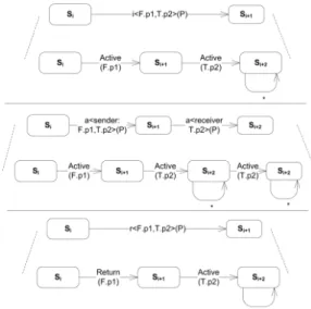
BEA-to-EOA conversion is a straightforward process, in which each transition is converted to consecutive transitions as shown in Figure 7. For example, here we can see that a transition for a synchronous interaction is converted to two transitions: one triggered when the sender port is active and the other one triggered when the receiver port becomes active. If the transition in BEA has a condition, then the same condition is attached to all corresponding transitions in EOA. The accept state at the end of an interaction in BEA is represented also with an accept state at the end of the last transition corresponding to the interaction.
Note that the wildcard (∗) transitions are used to en-sure that in between two activations, no other port is ac-tive. Assume that the setTSi contains all outgoing
transi-tions for the stateSi; then, the wildcard transition for this
state matches any observationΣ − TSi, whereΣ is the set
containing all outgoing transitions in EOA. As can be seen from Figure 7, every EOA state corresponding to an end of an interaction has a wildcard transition. However, the inter-mediatory states do not have such transitions. This means, that when the transition corresponding to the activation of the sender port is observed, then the next observation should be the activation of the sender port. If the activation of an-other port is observed, then the execution does not conform to the behavioral model. When the activation of the sender is observed, then we successfully observed an interaction and we stay on the current state until the activation of the sender port for the next interaction is observed.
Another useful feature of the wildcard transitions is that they allow ConArch to abstract from execution details. There can be many different interactions between two con-secutive interactions of a behavioral model, and such activa-tions without the wildcard transiactiva-tions would lead to a failure in the verification. With the wildcard transitions, these acti-vations do not lead to a failure and allowConArch to verify only the sequence of interactions specified in the scenario.
After EOA is generated,ConArch generates the runtime instrumentation aspects using the mappings provided by the user. Here, an aspect with one pointcut, one before, and one
after advice is generated for each mapping. The before and after advices defined on each pointcut send the messages ACTIVE( mappedport ) and RETURN( mappedport ) to
the runtime verifier, respectively. The pointcut specifica-tion differs according to the mapping. For a mapping to a method, the pointcut captures the execution of the mapped
Figure 7. The transitions of the BEA and their EOA equivalents
method and the receiver class. For a mapping to a call, the pointcut captures the mapped call and the class mak-ing the call. For a mappmak-ing to a call sequence, the pointcuts for each call is composed with logical OR. The advice code keeps an internal state and only notifies runtime veri-fier when the sequence is completed.
In the previous section, example mappings form the port
ResolutionStrategyControlInterface.ResRequest() are
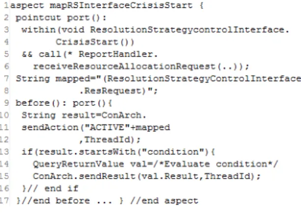
pre-sented. Figure 8 shows the aspect generated from one of these mappings. Here, the pointcut specification at line2-7 shows that the aspect captures the call within the method ResolutionStrategycontrolInterface.CrisisStart(); hence, this aspect is generated for the mapping to the call from ResolutionStrategycontrolInterface.CrisisStart() to ReportHandler.receiveResourceAllocationRequest().
At line 11 in Figure 8, we can see that the before ad-vice sends the message about the activation of the port with a ThreadId. We implemented the ConArch runtime veri-fier as a server process that receives the message from as-pects and evaluates state transitions for each thread/process. The ThreadId is used to identify the current state for a pro-cess/thread. If the transitions require a condition to be eval-uated, the server sends the monitored process the name of the condition to evaluate. Then, the monitor aspect asks the Prolog interpreter to evaluate the condition and sends the results of the evaluation to the verifier process. To facil-itate interactions among different processes, ConArch al-lows the coexistence of different ThreadId’s for transitions corresponding to interactions within a certain time frame. It is also possible to extendConArch with aspects that capture the calls to the socket library and communicate ThreadId’s among processes.
262 262 262 264
Figure 8. A Snippet from the the aspect gen-erated for a mapping of the port
Resolution-StrategyControlInterface.ResRequest()
When the evaluation for a process/thread reaches to an accept state,ConArch deletes the corresponding ThreadId. On the other hand, if the current state for a process/thread does not change for a certain period ( in a state with wild-card transition) or a trigger does not match to any of the outgoing transitions (in a state without a wildcard transi-tion), then the verification fails andConArch logs the state together with the violating triggers.
8
Application of ConArch
In order to testConArch we implemented a basic ver-sion of CMS in Java following the design shown in Figure 6. We also implemented two clients that send crisis update re-ports to CMS at random time intervals.
According to our mappings,ConArch generated 16 as-pects. These aspects mainly intercepted the calls from/to the class ReportHandler as many of the ports in the sce-nario map to the methods of this class. After letting the setup execute for an hour, we collected the evaluation re-sults. The evaluation showed that at runtime one violation of the behavioral model has occurred. Following the last correct state and the incorrect event, we identified that a synchronization error lead the class ReportHandler to re-turn a success message to a failed allocation message. This result shows thatConArch is successful in capturing incon-sistencies between the execution of the software system and its behavioral models.
Execution analysis has showed thatConArch introduced a runtime performance overhead on average by 5 seconds. Obviously, much of this time was due to the evaluation of the conditions (client/server communication was negligible as they both executed in the same computer). All4 condi-tions of the behavioral model had a similar implementation to the one presented in Section 6. As such, they were not
very complicated. When the conditions are complicated, the performance overhead can be an issue. One way to increase the efficiency ofConArch is to use dynamic rule assertion rather than foreign predicates. In this setup, the instrumen-tation aspects would be programmed to export the runtime state of the software system as Prolog facts. For example, an aspect can be implemented to intercept a mapped call and export the facts isinstance for each attribute of the ob-jects at the both end of the calls. As a future work, we plan to implement this mechanism.
9
Related Work
There exists several approaches to prevent inconsisten-cies between an architecture design and its implementation [3, 2]. However, these are mostly based on static analysis only. In [21], static and dynamic analysis are combined. Static analysis is used for deriving the dependencies and interactions among the software modules. Dynamic anal-ysis is used for determining the interactions that are actu-ally active and that frequently occur at runtime. This ap-proach focuses on structural constraints regarding standard-ized architectural models (e.g., design patterns, architec-tural styles), and not on behavioral constraints. The neces-sary conditions for conformance and the conditions for vio-lation are specified as Prolog clauses. These prolog clauses are manually defined and parameterized for reuse in differ-ent projects. In our approach,ConArch automatically gen-erates Prolog rules and facts. Only the mapping between the design models and the source code should be defined man-ually for whichConArch generates Prolog templates. In [12] architectural views are constructed based on runtime observations on an executing system. Inconsistencies with respect to the existing documentation are also highlighted during the reconstruction process. However, this work fo-cuses on the runtime structure of the architecture and not on the runtime behavior. In [5] the inconsistencies between method flows modeled with sequence diagrams and the im-plementation are captured. This approach, however, focuses on object-oriented execution details that are not part of ar-chitectural models.
There have been dynamic analysis techniques introduced [13, 16] for analyzing the runtime behavior of a system to support architecture reconstruction [1]. These techniques are mainly employed for the purpose of reverse engineer-ing. In [19], the data obtained from the dynamic analysis is represented as Prolog facts. This facilitates query-support to abstract away the details before the visualization of the ar-chitecture. Abstraction rules are defined as Prolog proposi-tions applied on the raw data. Many other dynamic analysis and architecture reconstruction techniques are surveyed in [7]. These are also introduced for reverse engineering, but not for verifying the consistency of an architecture
docu-263 263 263 265
mentation at runtime. Reverse engineered behavioral mod-els could be checked (offline) with respect to the existing documentation. However, there is a lack of formalized map-ping between the generated models and existing documents. As such, these approaches do not facilitate automated con-sistency checking.
In Section 4, we have introduced a domain-specific lan-guage for modeling behavioral scenarios. In this lanlan-guage, we have employed conditionals that are defined based on system states. These conditionals determine the flow of events among a set of alternative execution sequences. SysML [10] also includes such conditionals. However, in our case, these conditionals are much less detailed/complex and they only focus on interaction sequences. In this work, our goal was not to introduce a comprehensive system mod-eling language, but to define a language that has the neces-sary and just enough expressiveness for our purposes, i.e., runtime verification.
10
Conclusion
In this paper we have proposed a runtime verification approach,ConArch, for detecting inconsistencies between the architecture and the code. Inconsistencies between the architecture and the code can occur due to improper im-plementation of the code or the separate evolution of the code. We have focused on the behavioral models of the ar-chitecture and provided mechanisms to ensure that the code follows the interaction constraints and dynamic flow as de-fined in these behavioral models. The approach is largely automated by an integrated toolset that implements the ar-chitecture and the code patterns in Prolog and supports the automatic generation of runtime monitors for detecting in-consistencies. The application of the approach on a case study showed that ConArch is successful in capturing in-consistencies between the execution of the software system and its behavioral models. In our future work we will en-hance our toolset and apply the approach in the context of a large industrial case study.
References
[1] M. Abi-Antoun and J. Aldrich. Static extraction and confor-mance analysis of hierarchical runtime architectural struc-ture using annotations. SIGPLAN Notes, 44(10):321 – 340, 2009.
[2] J. Aldrich, C. Chambers, and D. Notkin. Architectural rea-soning in ArchJava. In ECOOP, volume 2374, pages 185– 193. 2002.
[3] J. Aldrich, C. Chambers, and D. Notkin. ArchJava: connect-ing software architecture to implementation. In ICSE, pages 187–197, 2002.
[4] L. Bass, P. Clements, and R. Kazman. Software Architecture
in Practice. Addison-Wesley, 2003.
[5] S. Ciraci, S. Malakuti, S. Katz, and M. Aksit. Checking the correspondence between uml models and implementation. In RV, volume 6418, pages 198–213. 2010.
[6] P. Clements, F. Bachmann, L. Bass, D. Garlan, J. Ivers, R. Little, R. Nord, and J. Stafford. Documenting Software
Architectures. Addison-Wesley, 2002.
[7] D. Pollet et al. Towards a process-oriented software archi-tecture reconstruction taxonomy. In CSMR, pages 137 – 148, 2007.
[8] D. Steinberg et al. EMF: Eclipse Modeling Framework. 2008.
[9] E. Dashofy, A. van der Hoek, and R. Taylor. An infrastruc-ture for the rapid development of XML-based architecinfrastruc-ture description languages. In ICSE, pages 266 – 276, 2002. [10] S. Friedenthal, A. Moore, and R. Steiner. A Practical Guide
to SysML: The Systems Modeling Language. Morgan
Kauf-mann Publishers Inc., 2008.
[11] G. Kiczales et al. Aspect-oriented programming. In
ECOOP, pages 220 – 242, 1997.
[12] H. Yan et al. DiscoTect: a system for discovering architec-tures from running systems. In ICSE, pages 470–479, 2004. [13] G. Huang, H. Mei, and F.-Q. Yang. Runtime recovery and manipulation of software architecture of component-based systems. IEEE Trans. on Software Engineering, 13(2):257 – 281, 2006.
[14] F. Jouault, J. Bezivin, and I. Kurtev. TCS: A DSL for the specification of textual concrete syntaxes in model engineer-ing. In GPCE, pages 249 – 254, 2006.
[15] J. Kienzle, N. Guelfi, and S. Mustafiz. Crisis management systems: A case study for aspect-oriented modeling. Trans.
on Aspect-Oriented Software Development, 6210/2010:1 –
22, 2010.
[16] L. Qingshan et al. Architecture recovery and abstraction from the perspective of processes. In WCRE, pages 57–66, 2005.
[17] M. Leucker and C. Schallhart. A brief account of runtime verification. Journal of Logic and Algebraic Programming, 78(5):293 – 303, 2008.
[18] G. Murphy, D. Notkin, and K. Sullivan. Software reflexion models: Bridging the gap between design and implemen-tation. IEEE Trans. on Software Engineering, 27(4):364 – 308, 2001.
[19] C. Riva and J. Rodriguez. Combining static and dynamic views for architecture reconstruction. In CSMR, pages 47– 55, 2002.
[20] S. Eick et al. Does code decay? assessing the evidence from change management data. IEEE Trans. on Software
Engi-neering, 27(1):1 – 12, 2001.
[21] M. Sefika, A. Sane, and R. Campbell. Monitoring compli-ance of a software system with its high-level design models. In ICSE, pages 387 – 396, 1996.
[22] R. Taylor, N. Medvidovic, and E. Dashofy. Software
Archi-tecture: Foundations, Theory, and Practice. 2009.
[23] R. Tvedt, P. Costa, and M. Lindvall. Does the code match the design? a process for architecture evaluation. In ICSM, pages 393 – 401, 2002.
264 264 264 266