IJAO
ISSN 0391-3988 ORIGINAL ARTIcLEgroove (IOG) branches from the inferior orbital fissure and is formed by the orbital floor of maxilla. These structures allow passage of the infraorbital vessels and nerve (2). The infraor-bital nerve (ION) is the continuation of the maxillary nerve, which is responsible for sensory innervation to the skin of ma-lar area between the lower eyelid and upper lip. The IOF is important anatomically in the infraorbital nerve block, espe-cially in regional anesthesia for the treatment of pathological conditions like cyst enucleation, for cleft palate and lip surgery, endoscopic sinus surgery in infants, and radiofrequency abla-tion of trigeminal ganglion in trigeminal neuralgia for elderly patients (3, 4). Beyond these therapies, in cases when the dis-section of the periosteum of the face is performed, such as in maxillary osteotomies or midfacial lift surgeries for the correc-tion of midfacial ptosis, surgeons must be careful of the loca-tion of the IOF (5, 6).
The use of cone-beam computed tomography (CBCT) was first reported by Mozzo et al (7) and has been proposed in the last decade for maxillofacial imaging (8, 9). A CBCT scan uses DOI: 10.5301/ijao.5000469
Morphometric analysis of the infraorbital foramen,
canal and groove using cone beam cT: considerations
for creating artificial organs
Kaan Orhan1, Melis Misirli2, secil Aksoy2, Umut seki1 Evren Hincal3, Tugrul Ormeci4, Ahmet Arslan5 1 Ankara University, Faculty of Dentistry, Department of Dentomaxillofacial Radiology, Ankara - Turkey
2 Near East University, Faculty of Dentistry, Department of Dentomaxillofacial Radiology, Mersin - Turkey 3 Near East University, Faculty of Arts & Sciences, Department of Mathematics, Mersin - Turkey 4 Medipol University, Faculty of Medicine, Department of Radiology, Istanbul - Turkey
5 Yeditepe University, Faculty of Dentistry, Department of Oral and Maxillofacial Surgery, Istanbul - Turkey
Introduction
The infraorbital foramen (IOF) is one of the most important facial foramens, and the infraorbital nerve emerges from the IOF and the branches to innervate the middle region of the face. The infraorbital canal (IOC) is located in the orbital part of maxilla and shows the upward and lateral course. It opens via the IOF just below the margin of orbit (1). The infraorbital
AbsTRAcT
Purpose: The aim of this study was to examine the anatomy and variations of the infraorbital foramen and its sur-roundings via morphometric measurements using cone beam computed tomography (CBCT) scans derived from a 3D volumetric rendering program.
Methods: 354 sides of CBCT scans from 177 patients were examined in this study. DICOM data from these images were exported to Maxilim® software in order to generate 3D surface models. The morphometric measurements were done for infraorbital foramen (IOF), infraorbital groove (IOG) and infraorbital canal (IOC). All images were evaluated by 1 radiologist. To assess intra-observer reliability, the Wilcoxon matched-pairs signed rank test was used. Differences between sex, side, age and measurements were evaluated using chi-square and paired t-test and measurements were evaluated using 1-way ANOVA tests. Differences were considered significant when p<0.05. Results: The most common shape was oval for IOF and parallel for IOC without any accessory foramen. The re-sults showed that females have smaller dimensions for the measurements between the two foramen rotundum (FR), FR-IOF, sella-FR, center of the IOF (cIOF)-nasion (N), cIOF-NB (nasion-B) (p>0.05). No significant difference was found according to age groups (p>0.05).
conclusions: These results provide detailed knowledge of the anatomical characteristics in this particular area. CBCT imaging with lower radiation dose and thin slices can be a powerful tool for anesthesia procedures like infra orbital nerve blocks, for surgical approaches like osteotomies and neurectomies and also for generating artificial prostheses. Keywords: Anatomical models, Anatomy, Cone beam computed tomography, Infraorbital foramen, Morphometric measurements, Surgical models
Accepted: January 26, 2016 Published online: February 9, 2016 corresponding author:
Dr. Kaan Orhan Ankara University Faculty of Dentistry
Department of Dentomaxillofacial Radiology Ankara, Turkey
a different type of acquisition than that used in multislice CT (MSCT). Rather than capturing an image as separate slices as in MDCT, CBCT produces a cone-shaped X-ray beam that allows an image to be captured in a single shot. The resul-tant volume can be reformatted to provide multiple recon-structed images (e.g., sagittal, coronal, and axial) that are similar to traditional MDCT images (10, 11). CBCT thus offers the distinct advantage of a lower radiation dose than MDCT and the possibility of importing and exporting individualized, overlap-free reconstructions. Moreover, these possibilities and increasing access to CBCT imaging for surgeons and are enabling the movement from 2D analysis to 3D analysis prior to all kinds of surgeries. Studies of CBCT applications in maxil-lofacial surgery have shown it to be a reliable and accurate tool for linear and 3D measurements prior to surgery (12).,
New technologies like CBCT-based models help to under-stand the anatomy and pathology of the hard tissues in living subjects. This innovative method reduces errors and contrib-utes to the development of new imaging markers for risk fac-tors (13). Gomez et al (14) developed computed tomography based models for assessing condylar morphology and report-ed that the 3D surface models constructreport-ed from CBCT images are comparable to those derived from MSCT scans. He also reported that CBCT is a reliable tool for considering condylar morphology.
Many anatomical studies of this region using cadavers have been reported in the literature in English (15-19), but to the best of our knowledge there is no study that compara-tively evaluates the anatomy of the IOF, IOC, IOG and their re-lations with neighborhood anatomical structures using CBCT imaging. It was therefore considered worthwhile to examine the anatomy and variations of the infraorbital foramen and its surroundings via morphometric measurements using cone beam CT scans derived from a volumetric rendering software.
Materials and methods
Data from CBCT examinations of 354 sites in 177 patients who had been referred to our outpatient clinic during a 5-year period were analyzed retrospectively. The overall mean age was 38.4 years (range: 18-70 years, standard deviation (SD): 16.7 years). Informed consent was obtained from all patients before CBCT examinations. The mean age of the male patients was 39.2 (SD, 17.66; n = 86) years (range, 18-69 years), while the mean age of the female patients was 37.6 (SD, 15.63; n = 91) years (range, 18-70 years).
Patients with evidence of bone disease (especially osteo-porosis), relevant drug consumption, skeletal asymmetries or trauma, congenital disorders, anamnesis of surgical pro-cedures in the TMJ, and pathological disorders of the maxilla and mandible as well as syndromic patients were excluded from the study. The study protocol was carried out accord-ing to the principles described in the Declaration of Helsinki, including all amendments and revisions. Only the investiga-tors had access to the collected data. The institutional review board of the faculty reviewed and approved informed con-sent forms. There was no preference for gender regarding sample choice. Only high-quality scans were included. Low-quality images, such as those containing scattering or insuffi-cient accuracy of bony borders, were excluded. Patients were
grouped according to gender and age groups: 18 to 25, 26 to 50, and 50 and over.
Imaging using CBCT
CBCT scans were obtained using a Newtom 3G (Quantita-tive Radiology). All CBCT scans were obtained according to the strict, standardized scanning protocol used in our clinic. Patients were placed in a horizontal position, checked to ensure that their mouths were closed in a normal, natural occlusive position and instructed to lie still throughout the length of the scan. Images were obtained using a 9-inch (0.25 mm3) or 12-inch (0.40 mm3) field of view (to ensure inclusion
of the entire facial anatomy), 0.3 mm-thick axial slices and isotropic voxels. Axial images were exported in a DICOM file format with a 512 × 512 matrix and imported to Maxilim® (version 2.3.0; Medicim). The anatomical and morphometric evaluations and measurements were done by means of this software.
All images were reconstructed on a 21.3-inch, flat- panel, color active matrix TFT medical display (Nio Color 3MP; Barco) with a resolution 76 Hz, 0.2115-mm pitch 10 bit. The examin-ers were also permitted to use enhancements and orienta-tion tools such as magnificaorienta-tion, brightness, and contrast to improve visualization of the landmarks.
Image evaluation
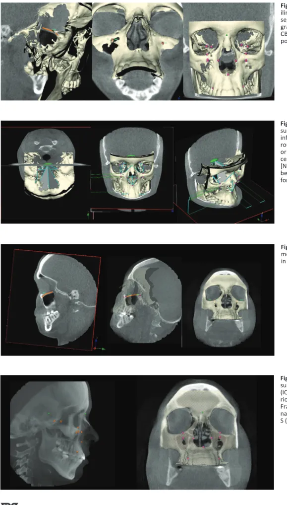
All CBCT images were retrospectively evaluated by a den-tomaxillofacial radiologist with 12 years of experience (K.O.). Image evaluations were done in sagittal and coronal CBCT slices together with superimposition of 3D skull representa-tions (Fig. 1).
On both sides, the size of the IOF was measured horizon-tally and vertically on X (the width) and Y axis (the height). The horizontal plane was defined as the plane that was paral-lel to the nasal floor and passed through the IOF; the vertical plane was defined as the plane that was parallel to the sagit-tal plane and passed through the IOF (Fig. 1).
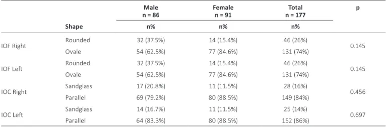
Besides the size, the shape of the IOF (oval or rounded), the shape of the IOC (parallel or hourglass), the presence of accessory IOF, the angle between the N (nasion)-IOF-S (sella), the angle between the N-S-IOF (Fig. 2), the distance between the foramen rotundum (FR)-IOF, the distance between FR- (in-ferior orbital fissure) (InfOF), the distance between IOF-IOF, S-center of IOF (cIOF), cIOF-N, InfOF-IOF, InfOF- (infraorbital margin) (IOM), cIOF- (the lateral process of the canine tooth) (CT), the distance between the upper pole of the IOF (uIOF)-IOM, cIOF-NB, the length of the IOC, the length of the IOM were measured on both sides (Figs. 2 and 3).
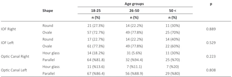
The length of the IOC was defined as the distance from the center of the IOF to the portion where the axis of the IOC changed. The length of the IOG was defined as the sum of the IOG uncovered by the bone and portion that was parallel to the orbital floor and covered by the bone. In addition to these measurements, ANS-NB, FR-FR, N-ANS, S-FR and S-N were all measured on both sides (Fig. 4).
Statistical analyses were performed using IBM SPSS soft-ware (version 20.0.1). Wilcoxon matched-pair, signed-rank tests were used to assess the intra-observer reliability of
Fig. 1 - General layout of the
Max-ilim® software showing hard-tissue segmentation together with radio-graphic slices in sagittal and coronal CBCT views together with superim-position of 3D skull representations.
Fig. 2 - Figure showing all
mea-surements [the size, the shape of infraorbital foramen (IOF) (oval or rounded), the shape of IOC (parallel or hourglass)], the presence of ac-cessory IOF, the angle between the [N (nasion)-IOF-S (sella), the angle between the N-S-IOF] that was per-formed in the study.
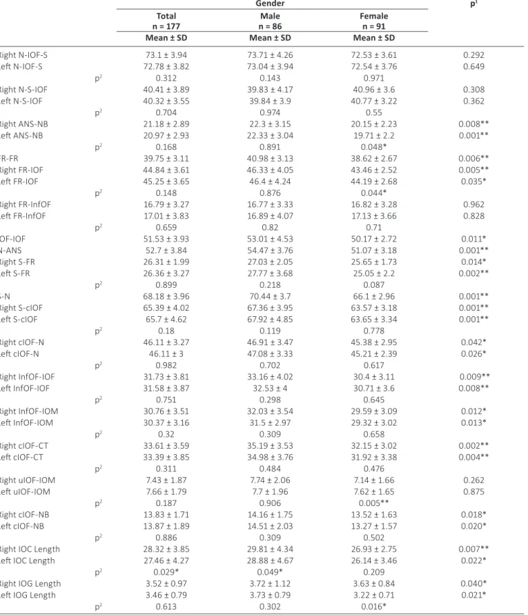
Fig. 3 - Figure showing the
measure-ment of the infraorbital canal (IOC) in different slices.
Fig. 4 - Figure showing the
mea-surements of the infraorbital canal (IOC), infraorbital grove (IOG), ante-rior nasal spine- NB line (ANS-NB), Frankfort horizontal plane (FR-FR), nasion-anterior nasal spine (N-ANS), S (sella)-FR and SN landmarks.
repeated measurements and examinations. Differences be-tween sex, side, age and measurements were evaluated using chi-square and paired t-test and measurements were evalu-ated using 1-way ANOVA tests. Differences were considered significant when p<0.05.
Results
Repeated measurements of CBCTs showed no significant intra-observer difference (p>0.05). Overall, intra-observer consistency was 94.2% between 2 measurements. All mea-surements were found to be highly reproducible. The aver-age of the measurements was constituted as final data for the study.
The horizontal (x axis) and the vertical (y axis) measure-ments are presented in Table I. Although no statistically sig-nificant difference was observed between males and females, the size of IOF was always bigger in males (p>0.05). Table II shows the shape of the IOF and IOC for left and right sides. Examination of the 354 sides of the 177 CBCT scans revealed
that the most common shape was oval for the IOF, parallel for the IOC and there was no accessory foramen. In addition, no statistically significant difference was observed between the genders on both sides (p>0.05).
The measurement between ANS-NB, FR-FR, FR-IOF, IOF-IOF, N-ANS, S-FR, S-N, S-cIOF-IOF, cIOF-N, InfOF-IOF-IOF, InfOF-IOM, cIOF-CT, cIOF-NB, IOC length and IOG length were all signifi-cantly greater in males (Tab. III). In all cases the average of the IOC length on the right side was determined to be signifi-cantly higher compared to the left side (p = 0.029; p<0.05). In all males, the average length of the IOC obtained on the right side was higher compared to the left side (p = 0.049; p<0.05).
Table IV shows the width of the IOF on the X axis and the height of the IOF on the Y axis according to age groups. No statistically significant difference was noticed between young and older ones. Table V shows the shape of the IOF, either round or oval, according to same age groups. It also shows the shape of the optic canal either sand glass or parallel. No statistically significant difference was obtained regarding the shape of the optic canal and the IOF.
TAbLE I - Measurements of the infraorbital foramen (IOF) on the x axis (width) and y axis (height) in different sexes Total
n = 177 n = 86Male Female n = 91 p
1
Mean ± sD Mean ± sD Mean ± sD
IOF Right X Axis 3.52 ± 0.81 3.53 ± 0.75 3.51 ± 0.78 0.076
IOF Left X Axis 3.66 ± 0.88 3.86 ± 0.91 3.46 ± 0.79 0.595
p2 0.776 0.218 0.237
IOF Right Y Axis 4.84 ± 1.21 5.10 ± 1.44 4.58 ± 1.11 0.079
IOF Left Y Axis 4.82 ± 1.29 5.05 ± 1.38 4.59 ± 1.13 0.492
p2 0.760 0.296 0.786
1 Student’s t-test.
2 Paired sample t-test; *p<0.05.
TAbLE II - Determination of the shape of the infraorbital foramen (IOF) and the infraorbital canal (IOC) in different sexes Male
n = 86 Female n = 91 n = 177Total p shape n% n% n%
IOF Right Rounded 32 (37.5%) 14 (15.4%) 46 (26%) 0.145
Ovale 54 (62.5%) 77 (84.6%) 131 (74%)
IOF Left Rounded 32 (37.5%) 14 (15.4%) 46 (26%) 0.145
Ovale 54 (62.5%) 77 (84.6%) 131 (74%)
IOC Right Sandglass 17 (20.8%) 11 (11.5%) 28 (16%) 0.456
Parallel 69 (79.2%) 80 (88.5%) 149 (84%)
IOC Left Sandglass 14 (16.7%) 11 (11.5%) 25 (14%) 0.697
Parallel 64 (83.3%) 80 (88.5%) 152 (86%)
TAbLE III - Measurements of the infraorbital foramen (IOF) and several anatomic landmarks around the IOF
Gender p1
Total
n = 177 n = 86Male Female n = 91 Mean ± sD Mean ± sD Mean ± sD
Right N-IOF-S 73.1 ± 3.94 73.71 ± 4.26 72.53 ± 3.61 0.292 Left N-IOF-S 72.78 ± 3.82 73.04 ± 3.94 72.54 ± 3.76 0.649 p2 0.312 0.143 0.971 Right N-S-IOF 40.41 ± 3.89 39.83 ± 4.17 40.96 ± 3.6 0.308 Left N-S-IOF 40.32 ± 3.55 39.84 ± 3.9 40.77 ± 3.22 0.362 p2 0.704 0.974 0.55 Right ANS-NB 21.18 ± 2.89 22.3 ± 3.15 20.15 ± 2.23 0.008** Left ANS-NB 20.97 ± 2.93 22.33 ± 3.04 19.71 ± 2.2 0.001** p2 0.168 0.891 0.048* FR-FR 39.75 ± 3.11 40.98 ± 3.13 38.62 ± 2.67 0.006** Right FR-IOF 44.84 ± 3.61 46.33 ± 4.05 43.46 ± 2.52 0.005** Left FR-IOF 45.25 ± 3.65 46.4 ± 4.24 44.19 ± 2.68 0.035* p2 0.148 0.876 0.044* Right FR-InfOF 16.79 ± 3.27 16.77 ± 3.33 16.82 ± 3.28 0.962 Left FR-InfOF 17.01 ± 3.83 16.89 ± 4.07 17.13 ± 3.66 0.828 p2 0.659 0.82 0.71 IOF-IOF 51.53 ± 3.93 53.01 ± 4.53 50.17 ± 2.72 0.011* N-ANS 52.7 ± 3.84 54.47 ± 3.76 51.07 ± 3.18 0.001** Right S-FR 26.31 ± 1.99 27.03 ± 2.05 25.65 ± 1.73 0.014* Left S-FR 26.36 ± 3.27 27.77 ± 3.68 25.05 ± 2.2 0.002** p2 0.899 0.218 0.087 S-N 68.18 ± 3.96 70.44 ± 3.7 66.1 ± 2.96 0.001** Right S-cIOF 65.39 ± 4.02 67.36 ± 3.95 63.57 ± 3.18 0.001** Left S-cIOF 65.7 ± 4.62 67.92 ± 4.85 63.65 ± 3.34 0.001** p2 0.18 0.119 0.778 Right cIOF-N 46.11 ± 3.27 46.91 ± 3.47 45.38 ± 2.95 0.042* Left cIOF-N 46.11 ± 3 47.08 ± 3.33 45.21 ± 2.39 0.026* p2 0.982 0.702 0.617 Right InfOF-IOF 31.73 ± 3.81 33.16 ± 4.02 30.4 ± 3.11 0.009** Left InfOF-IOF 31.58 ± 3.87 32.53 ± 4 30.71 ± 3.6 0.008** p2 0.751 0.298 0.645 Right InfOF-IOM 30.76 ± 3.51 32.03 ± 3.54 29.59 ± 3.09 0.012* Left InfOF-IOM 30.37 ± 3.16 31.5 ± 2.97 29.32 ± 3.02 0.013* p2 0.32 0.309 0.658 Right cIOF-CT 33.61 ± 3.59 35.19 ± 3.53 32.15 ± 3.02 0.002** Left cIOF-CT 33.39 ± 3.85 34.98 ± 3.76 31.92 ± 3.38 0.004** p2 0.311 0.484 0.476 Right uIOF-IOM 7.43 ± 1.87 7.74 ± 2.06 7.14 ± 1.66 0.262 Left uIOF-IOM 7.66 ± 1.79 7.7 ± 1.96 7.62 ± 1.65 0.875 p2 0.187 0.906 0.005** Right cIOF-NB 13.83 ± 1.71 14.16 ± 1.75 13.52 ± 1.63 0.018* Left cIOF-NB 13.87 ± 1.89 14.51 ± 2.03 13.27 ± 1.57 0.020* p2 0.886 0.309 0.502
Right IOC Length 28.32 ± 3.85 29.81 ± 4.34 26.93 ± 2.75 0.007**
Left IOC Length 27.46 ± 4.27 28.88 ± 4.67 26.14 ± 3.46 0.022*
p2 0.029* 0.049* 0.209
Right IOG Length 3.52 ± 0.97 3.72 ± 1.12 3.63 ± 0.84 0.040*
Left IOG Length 3.46 ± 0.79 3.73 ± 0.79 3.22 ± 0.71 0.021*
p2 0.613 0.302 0.016*
1 Student’s t-test. 2 Paired sample t-test. * p<0.05.
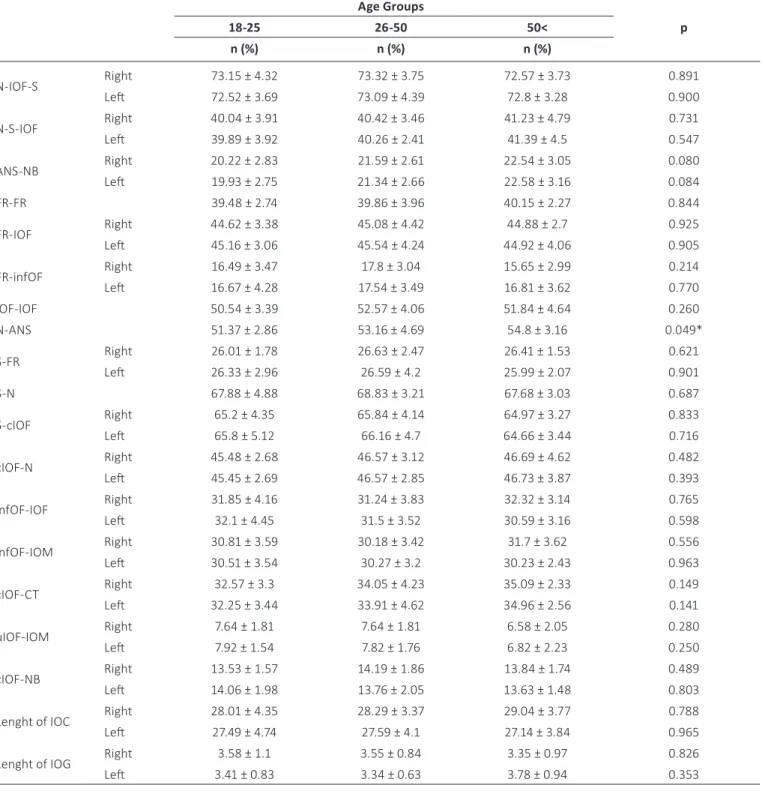
Table VI shows the measurements of neighborhood an-atomical region of the IOF between the right and left sides and also the measurement of the FR-FR, IOF-IOF, N-ANS, S-N according to age groups. No statistically significant dif-ference was observed on the left side of the ANS-NB and N-ANS in both measurements between the age groups (p>0.05).
Discussion
CT and CBCT modalities that have come into use over the past decade have been found to overcome the limitations in surgical procedures. As a result of technological advances in the imaging, the CBCT 3D imaging technique has become used routinely especially for ENT (Ear-nose-throat) and max-illofacial presurgical imaging purposes (9, 11). In general, CBCT has been recommended as a dose-sparing technique, compared with standard medical CT scans, for the imaging of anatomical landmarks before surgical procedures. The effec-tive dose (ICRP 2007) (International commission on radiologi-cal protection) from a standard dental protocol scan using a traditional CT was 1.5 to 12.3 times greater than comparable medium-FOV dental CBCT scans. CBCT image quality has also
been found to be equivalent to that of traditional CT for visu-alizing the maxillofacial structures (12, 20, 21).
CBCT has a revolutionary role in the diagnosis and treat-ment planning of craniofacial disorders. The lower radiation dose and cost compared with MSCT provide clinicians with a valuable diagnostic tool for identifying specific changes in the morphology of craniofacial regions like the mandibular con-dyles with osteoarthritis (22). CBCT-based, 3D surface models provide additional diagnostic information on size, shape and the exact location of the bone abnormality of the affected joint (14).
Determination of IOF is important for percutaneous in-terventions. Although it is important to palpate and identify the location of IOF under soft tissue and skin, the knowledge of the position of the IOF and related structures such as the IOC and the IOG is useful for a safe block of the infraorbitalis nerve. Recently, a CT-based, 3D reconstruction method has made it possible to measure the lengths and angles of various structures in the craniofacial bone with certain software. The reliability and accuracy of this method has been proved by previous studies (10, 23). After identifying anatomical land-marks around the IOF, we made necessary measurements on 3D models between these landmarks.
TAbLE IV - Measurements of the infraorbital foramen (IOF) on the x axis (width) and y axis (height) in different age groups Age Groups p 18-25 26-50 50<
Mean ± sD Mean ± sD Mean ± sD
Infraorbital foramen Right X axis 3.46 ± 0.62 3.57 ± 1.06 3.53 ± 1.25 0.319
Infraorbital foramen Right Y axis 4.85 ± 0.99 4.80 ± 1.08 4.87 ± 1.35 0.374
Infraorbital foramen Left X axis 3.57 ± 0.84 3.74 ± 0.82 3.67 ± 0.73 0.344
Infraorbital foramen Left Y axis 4.72 ± 1.11 4.91 ± 1.52 4.81 ± 1.87 0.923
Number of males = 86; number of females = 91.
TAbLE V - Determination of the shape of the infraorbital foramen (IOF) and optic canal in different age groups
Age groups p shape 18-25 26-50 50 <
n (%) n (%) n (%)
IOF Right Round 21 (27.3%) 14 (22.2%) 11 (30%) 0.889
Ovale 57 (72.7%) 49 (77.8%) 25 (70%)
IOF Left Round 17 (22.7%) 14 (22.2%) 14 (40%) 0.529
Ovale 61 (77.3%) 49 (77.8%) 22 (60%)
Optic Canal Right Hour glass 14 (18.2%) 31 (5.6%) 11 (30%) 0.223
Parallel 64 (%81.8) 32 (%94.4) 25 (%70)
Optic Canal Left Hour glass 11 (%13.6) 7 (%11.1) 7 (%20) 0.808
Parallel 67 (%86.4) 56 (%88.9) 29 (%80)
TAbLE VI - Measurements of the infraorbital foramen (IOF) and several anatomic landmarks around the IOF in different age groups Age Groups 18-25 26-50 50< p n (%) n (%) n (%) N-IOF-S Right 73.15 ± 4.32 73.32 ± 3.75 72.57 ± 3.73 0.891 Left 72.52 ± 3.69 73.09 ± 4.39 72.8 ± 3.28 0.900 N-S-IOF Right 40.04 ± 3.91 40.42 ± 3.46 41.23 ± 4.79 0.731 Left 39.89 ± 3.92 40.26 ± 2.41 41.39 ± 4.5 0.547 ANS-NB Right 20.22 ± 2.83 21.59 ± 2.61 22.54 ± 3.05 0.080 Left 19.93 ± 2.75 21.34 ± 2.66 22.58 ± 3.16 0.084 FR-FR 39.48 ± 2.74 39.86 ± 3.96 40.15 ± 2.27 0.844 FR-IOF Right 44.62 ± 3.38 45.08 ± 4.42 44.88 ± 2.7 0.925 Left 45.16 ± 3.06 45.54 ± 4.24 44.92 ± 4.06 0.905 FR-infOF Right 16.49 ± 3.47 17.8 ± 3.04 15.65 ± 2.99 0.214 Left 16.67 ± 4.28 17.54 ± 3.49 16.81 ± 3.62 0.770 IOF-IOF 50.54 ± 3.39 52.57 ± 4.06 51.84 ± 4.64 0.260 N-ANS 51.37 ± 2.86 53.16 ± 4.69 54.8 ± 3.16 0.049* S-FR Right 26.01 ± 1.78 26.63 ± 2.47 26.41 ± 1.53 0.621 Left 26.33 ± 2.96 26.59 ± 4.2 25.99 ± 2.07 0.901 S-N 67.88 ± 4.88 68.83 ± 3.21 67.68 ± 3.03 0.687 S-cIOF Right 65.2 ± 4.35 65.84 ± 4.14 64.97 ± 3.27 0.833 Left 65.8 ± 5.12 66.16 ± 4.7 64.66 ± 3.44 0.716 cIOF-N Right 45.48 ± 2.68 46.57 ± 3.12 46.69 ± 4.62 0.482 Left 45.45 ± 2.69 46.57 ± 2.85 46.73 ± 3.87 0.393 infOF-IOF Right 31.85 ± 4.16 31.24 ± 3.83 32.32 ± 3.14 0.765 Left 32.1 ± 4.45 31.5 ± 3.52 30.59 ± 3.16 0.598 infOF-IOM Right 30.81 ± 3.59 30.18 ± 3.42 31.7 ± 3.62 0.556 Left 30.51 ± 3.54 30.27 ± 3.2 30.23 ± 2.43 0.963 cIOF-CT Right 32.57 ± 3.3 34.05 ± 4.23 35.09 ± 2.33 0.149 Left 32.25 ± 3.44 33.91 ± 4.62 34.96 ± 2.56 0.141 uIOF-IOM Right 7.64 ± 1.81 7.64 ± 1.81 6.58 ± 2.05 0.280 Left 7.92 ± 1.54 7.82 ± 1.76 6.82 ± 2.23 0.250 cIOF-NB Right 13.53 ± 1.57 14.19 ± 1.86 13.84 ± 1.74 0.489 Left 14.06 ± 1.98 13.76 ± 2.05 13.63 ± 1.48 0.803
Lenght of IOC Right 28.01 ± 4.35 28.29 ± 3.37 29.04 ± 3.77 0.788
Left 27.49 ± 4.74 27.59 ± 4.1 27.14 ± 3.84 0.965
Lenght of IOG Right 3.58 ± 1.1 3.55 ± 0.84 3.35 ± 0.97 0.826
Left 3.41 ± 0.83 3.34 ± 0.63 3.78 ± 0.94 0.353
Number of males = 86; number of females = 91.
First of all, if a surgeon wants to perform an ION (infraor-bital nerve) block or neurectomy, he or she must be aware of the location, slope of the canal and number of the foramina. Aggarwall et al (24) examined 67 dried, intact, adult skulls and stated that 21% of them contained multiple foramina. In the present study, all subjects appeared with only 1 single in-fraorbital foramen on each side of their skull. Regarding the
slope of the canal, the surgeon must insert the needle up-ward and laterally (25). As already known, the IOC continues in the IOG located in the orbital floor; the tip of the needle must not be placed too posteriorly to avoid damaging the or-bital structures or pterygopalatine fossa. In the present study, the average length of the IOC was found to be 29.81 ± 4.34 (right side for males), 28.88 ± 4.67 (left side for males), 26.93
± 2.75 (right side for females) and 26.14 ± 3.46 (left side for females). These values were all bigger compared to the study by Hwang et al (26) in which they measure 11.7 mm. How-ever, Kazkayasi et al (18) and Rahman et al (19) measured 22.95 mm and 13 mm. The mean length of the IOG was found to be 3.52 ± 0.97 mm on the right side and 3.46 ± 0.79 mm on the left side in the present study. This was different from the 16.7-mm length found by Hwang et al (26), the 5.95-mm length found by Kazayasi et al (18) and the 14-mm length found by Rahman et al (19). These different measurements of the IOG and the IOC may be due to their definitions. In the present study, the IOC was identified as the distance from the IOF to the portion covered by the bone of the orbital floor.
Previous studies reported that the supraorbital notch (foramen), midline, infraorbital rim and ANS were taken as reference points for the determination of the location of the IOF (15, 16, 18, 27). Chung et al (16), stated that the IOF was 27.2 mm lateral to the midline in Koreans. Hwang et al (26) indicated that the distance of the IOF from the midline was 26.5 mm. Similarly, the IOF was approximately 25.7 mm (26.5 mm in males, 25.08 mm in females) lateral to the mid-line in this study. Chrcanovic et al (28) reported that the mean location of the IOF was 6.5 mm inferior of the inferior orbital rim compared to the 9.6-mm measured by Hwang et al (26) and to our study, which found 7.43 mm on the right side and 7.66 mm on the left side. The discrepancy in the measurement may again be due to the definition of the reference point: the upper pole of the IOF was taken as the reference point for the measurement. Because the measurements may vary consid-erably among ethnicities and individuals, we aimed to locate the IOF with less variability from the surrounding structures more conveniently in living subjects by using the ANS as a reference point.
Regarding the oval or rounded shape of the IOF, although most of the foramen are oval, we found no statistically signifi-cant difference (Tab. I). Singh (29) reported 3 different shapes of infraorbital foramen, i.e., vertical oval, horizontal oval and circular, but he also reported that most of them were ver-tical oval. In the present study, the change in the shape of infraorbital foramen was also examined, but no statistically significant difference was observed between the age groups regarding the oval or round shape of the optic canal and the IOF according to age groups (Tab. V). Previous studies stated that the location of the IOF changes by age (5, 30). Facial bones show rapid growth from ages 3 to 4 years, and the or-bit was found to attain maturity at the age of 16 years (31, 32). Lee et al (5) also reported that the mean distance be-tween dacryon-IOF and IOF-IOM was stabilized after 20 years. In the present study no statistically significant difference was observed between young and older subjects (Tab. IV). It is noted than our study population only comprises people be-tween 18 and 70 years old, which means that the growth in the youngest group (18-25 years old) was already completed, resulting in no significant difference. In addition, the lengths of the ANS-NB, FR-FR, FR-IOF, IOF-IOF, N-ANS, S-FR, S-N, S-cIOF, cIOF-N , InfOF-IOF, InfOF-IOM, cIOF-CT, cIOF-NB, IOC and IOG were all significantly greater in males (Tab. III). In all cases the average of the IOC length on the right side was de-termined to be significantly longer compared to the left side (p = 0.029; p<0.05) (Tab. III). In all males, the average length
of the IOC on the right side was found to be longer compared to the left side (Tab. III).
conclusions
In conclusion, it may be stated that the size of the IOF and the distance between the IOF and most of the anatomical points differ between sexes. These results provide detailed knowledge of the anatomical characteristics in this particu-lar area. CBCT imaging with lower radiation doses and in thin slices can be a powerful tool prior to any surgical approach and for generating artificial prostheses.
Disclosures
Financial support: No grants or funding have been received for this study.
Conflicts of interest: None of the authors has financial interest re-lated to this study to disclose.
References
1. Sharma N, De M, Pracy P. Recurrent facial paraesthesia second-ary to maxillsecond-ary antral cyst and dehiscent infraorbital canal: case report. J Laryngol Otol. 2007;121(06):e6.
2. Abed SF, Shams PN, Shen S, Adds PJ, Uddin JM. Morphometric and geometric anatomy of the caucasian orbital floor. Orbit. 2011;30(5):214-220.
3. Gray H, Clemente CD, eds. Gray’s Anatomy of the Human Body. Baltimore, MD: Williams and Wilkins 2008.
4. Suresh S, Patel AS, Dunham ME, et al. A randomized double-blind controlled trial of infraorbital nerve block versus intra-venous morphine sulfate for children undergoing endoscopic sinus surgery: are postoperative outcomes different? Anesthe-siology. 2002;96:A1292.
5. Lee T, Lee H, Baek S. A three-dimensional computed tomo-graphic measurement of the location of infraorbital foramen in East Asians. J Craniofac Surg. 2012;23(4):1169-1173.
6. Schultze-Mosgau S, Krems H, Ott R, Neukam FW. A prospective electromyographic and computer-aided thermal sensitivity as-sessment of nerve lesions after sagittal split osteotomy and Le Fort I osteotomy. J Oral Maxillofac Surg. 2001;59(2):128-138, discussion 138-139.
7. Mozzo P, Procacci C, Tacconi A, Martini PT, Andreis IA. A new volumetric CT machine for dental imaging based on the cone-beam technique: preliminary results. Eur Radiol. 1998;8(9):1558-1564.
8. Brown AA, Scarfe WC, Scheetz JP, Silveira AM, Farman AG. Lin-ear accuracy of cone beam CT derived 3D images. Angle Or-thod. 2009;79(1):150-157.
9. Oz U, Orhan K, Abe N. Comparison of linear and angular mea-surements using two-dimensional conventional methods and three-dimensional cone beam CT images reconstructed from a volumetric rendering program in vivo. Dentomaxillofac Radiol. 2011;40(8):492-500.
10. Hwang SH, Seo JH, Joo YH, Kim BG, Cho JH, Kang JM. An ana-tomic study using three-dimensional reconstruction for ptery-gopalatine fossa infiltration via the greater palatine canal. Clin Anat. 2011;24(5):576-582.
11. Kalender A, Orhan K, Aksoy U. Evaluation of the mental fora-men and accessory fora-mental forafora-men in Turkish patients us-ing cone-beam computed tomography images reconstructed from a volumetric rendering program. Clin Anat. 2012;25(5): 584-592.
12. Liang X, Jacobs R, Hassan B, et al. A comparative evaluation of Cone Beam Computed Tomography (CBCT) and Multi-Slice CT (MSCT) Part I. On subjective image quality. Eur J Radiol. 2010;75(2):265-269.
13. Cevidanes LH, Hajati AK, Paniagua B, et al. Quantification of condylar resorption in temporomandibular joint osteoar-thritis. Oral Surg Oral Med Oral Pathol Oral Radiol Endod. 2010;110(1):110-117.
14. Gomes LR, Gomes MR, Gonçalves JR, et al. Cone beam com-puted tomography-based models versus multislice spiral computed tomography-based models for assessing condy-lar morphology. Oral Surg Oral Med Oral Pathol Oral Radiol. 2016;121(1):96-105.
15. Boopathi S, Chakravarthy Marx S, Dhalapathy SL, Anupa S. An-thropometric analysis of the infraorbital foramen in a South Indian population. Singapore Med J. 2010;51(9):730-735 16. Chung MS, Kim HJ, Kang HS, Chung IH. Locational
relation-ship of the supraorbital notch or foramen and infraorbital and mental foramina in Koreans. Acta Anat (Basel). 1995;154(2): 162-166.
17. Gupta T. Localization of important facial foramina encountered in maxillo-facial surgery. Clin Anat. 2008;21(7):633-640. 18. Kazkayasi M, Ergin A, Ersoy M, Bengi O, Tekdemir I, Elhan A.
Certain anatomical relations and the precise morphometry of the infraorbital foramen—canal and groove: an anatomical and cephalometric study. Laryngoscope. 2001;111(4):609-614. 19. Rahman M, Richter EO, Osawa S, Rhoton AL Jr. Anatomic study
of the infraorbital foramen for radiofrequency neurotomy of the infraorbital nerve. Neurosurgery. 2009;64(5)(Suppl 2): 423-427, discussion 427-428.
20. Ludlow JB, Ivanovic M. Comparative dosimetry of dental CBCT devices and 64-slice CT for oral and maxillofacial radiology. Oral Surg Oral Med Oral Pathol Oral Radiol Endod. 2008;106(1): 106-114.
21. Periago DR, Scarfe WC, Moshiri M, Scheetz JP, Silveira AM, Farman AG. Linear accuracy and reliability of cone beam CT de-rived 3-dimensional images constructed using an orthodontic
volumetric rendering program. Angle Orthod. 2008;78(3): 387-395.
22. Alexiou K, Stamatakis H, Tsiklakis K. Evaluation of the severity of temporomandibular joint osteoarthritic changes related to age using cone beam computed tomography. Dentomaxillofac Radiol. 2009;38(3):141-147.
23. Ji Y, Qian Z, Dong Y, Zhou H, Fan X. Quantitative morphometry of the orbit in Chinese adults based on a three-dimensional reconstruction method. J Anat. 2010;217(5):501-506.
24. Aggarwal A, Kaur H, Gupta T, et al. Anatomical study of the infraorbital foramen: A basis for successful infraorbital nerve block. Clin Anat. 2015;28(6):753-760.
25. Lee UY, Nam SH, Han SH, Choi KN, Kim TJ. Morphological char-acteristics of the infraorbital foramen and infraorbital canal us-ing three-dimensional models. Surg Radiol Anat. 2006;28(2): 115-120.
26. Hwang SH, Kim SW, Park CS, Kim SW, Cho JH, Kang JM. Morpho-metric analysis of the infraorbital groove, canal, and foramen on three-dimensional reconstruction of computed tomogra-phy scans. Surg Radiol Anat. 2013;35(7):565-571.
27. Agthong S, Huanmanop T, Chentanez V. Anatomical variations of the supraorbital, infraorbital, and mental foramina related to gender and side. J Oral Maxillofac Surg. 2005;63(6):800-804. 28. Chrcanovic BR, Abreu MH, Custódio AL. A morphometric analy-sis of supraorbital and infraorbital foramina relative to surgical landmarks. Surg Radiol Anat. 2011;33(4):329-335.
29. Singh R. Morphometric analysis of infraorbital foramen in In-dian dry skulls. Anat Cell Biol. 2011;44(1):79-83.
30. Suresh S, Voronov P, Curran J. Infraorbital nerve block in chil-dren: a computerized tomographic measurement of the loca-tion of the infraorbital foramen. Reg Anesth Pain Med. 2006; 31(3):211-214.
31. Enlow DH. Facial Growth. 3rd ed. Philadelphia, PA: WB Saunders Company 1990.
32. Schumacher GH. Principles of skeletal growth. In: Dixon A, Hoyte D, Ronning O, eds. Fundamentals of Craniofacial Growth. Boca Raton, FL: CRC Press 1997;1-21.