IEEE TRANSACTIONS ON MICROWAVE THEORY AND TECHNIQUES, VOL. 43, NO. 7, JULY 1995 1545
Closed-Form Green’
s
Functions for
General Sources and Stratified Media
Gulbin Dural, Member, IEEE, and M. I. Aksun, Member, IEEEAbstract-The closed-form Green’s functions of the vector and scalar potentials in the spatial domain are presented for the sources of horizontal electric, magnetic, and vertical electric, magnetic dipoles embedded in general, multilayer, planar media. First, the spectral domain Green’s functions in an arbitrary layer are derived analytically from the Green’s functions in the source layer by using a recursive algorithm. Then, the spatial domain Green’s functions are obtained by adding the contributions of the direct terms, surface waves, and complex images approximated
by the Generalized Pencil of Functions Method (GPOF). In the derivations, the main emphasis is to put these closed-form representations in a suitable form for the solution of the mixed potential integral equation (MPIE) by the method of moments in a general three-dimensional geometry. The contributions of this paper are: 1) providing the complete set of closed-form Green’s functions in spectral and spatial domains for general stratified media; 2) using the GPOF method, which is more robust and less noise sensitive, in the derivation of the closed-form spatial domain Green’s functions; and 3) casting the closed-form Green’s functions in a form to provide efficient applications of the method of moments.
I. INTRODUCTION
UE to the increased use of multilayer microstrip geome-
D
tries in the application of microstrip antennas [1]-[6] and monolithic microwave integrated circuits [7]-[ 111, the lay- ered geometries have recently attracted widespread attention. Therefore, a considerable amount of interest has been focused on the development of a rigorous and yet computationally efficient computer-aided design tools for microstrip geometries in a layered medium.The rigorous analysis of layered microstrip structures re- quires the computation of the Green’s functions for multilayer media, which are traditionally represented by the Sommerfeld integrals in the spatial domain, and by closed-form expressions in the spectral domain. When these traditional expressions for the Green’s functions are employed in the method of moments (MOM), the numerical evaluation of the MOM matrix elements becomes very time consuming in either domain, because the integrals involved are oscillatory and slow decaying functions
[ 121. To alleviate this problem, the spatial domain Green’s functions for the vector and scalar potentials, represented by the Sommerfeld integrals, are approximated by closed-form
Z=Z ,-h region -(i+l) region-(I) z=d i-h z=-h (HED,VED,HMD,VMD) region-(i-l) z=-d i-1 -h region-(i-m) Z=-I: -m -h
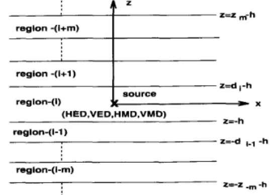
Fig. 1. Sources embedded in a multilayer medium.
expressions and used in the solution of the mixed potential integral equation (MPIE) by the MOM. This approach of approximating the spectral domain Green’s functions was first proposed in [13] for a horizontal electric dipole (HED) over a thick substrate backed by a ground plane and extended to a geometry with a substrate and a superstrate with arbitrary
thicknesses [ 141, using the original and least-square Prony’s methods [16], respectively. It was demonstrated that the use of the closed-form Green’s functions in the analysis of a microstrip geometry via the MOM improves the computational efficiency significantly [ 151.
In this paper, the closed-form Green’s functions of the vec- tor and scalar potentials of a Horizontal Electric Dipole (HED), Horizontal Magnetic Dipole (HMD), Vertical Electric Dipole (VED), and a Vertical Magnetic Dipole (VMD) located in an arbitrary layer of a planar-layered medium are presented. The layers are considered to have different dielectric and magnetic properties ( e r , p r ) or are made of perfect electric or magnetic conductors (PEC, PMC), as shown in Fig. 1. The Green’s functions are first obtained in the spectral domain, which can be represented in closed-form, in the source layer and these expressions are extended to an arbitrary layer using an iterative algorithm [8] for
TE
and TM components individually. Then, the spatial domain closed-form Green’s functions are obtainedManuscript received December 9, 1993; revised December 31, 1994. This work was supported in part by NATO’s Scientific Affairs Division in the framework of the Science for Stability Programme and Cost 223 and Cost 245 projects.
G. Dural is with the Department of Electrical and Electronics Engineering, M. I. Aksun is with the Department of Electrical and Electronics Engineer-
by adding the contributions of the direct terInS and Surface waves to the complex images approximated by the Generalized Pencil of Functions (GPOF) method [17], which is less noise sensitive and more efficient than the Prony’s methods. Since the spectral domain Green’s functions, excluding the direct term and the surface wave components, are approximated by the GPOF method, their dependence on z must be kept in
Middle East Technical University, 0653 1 Ankara, Turkey. ing, Bilkent University, 06533 Ankara, Turkey.
IEEE Log Number 9412042.
1546 IEEE TRANSACTIONS ON MICROWAVE THEORY AND TECHNIQUES, VOL. 43, NO. I, JUL'I' 1995
explicit form to avoid the repeated use of GPOF approximation and to increase the computational efficiency in cases of vertical connections. Since the Green's functions for the vector and scalar potentials are not uniquely defined in stratified media
[ 181, [ 191, the closed-form representations of an alternative formulation of the Green's functions are also provided, which might be used in cases where the vertical and horizontal sources are present at the same point [20].
Derivation of the closed-form Green's functions are given in Section I1 and the numerical considerations associated with their evaluation are discussed. In Section 111, some numerical examples of the closed-form Green's functions are presented for two different multilayer geometries and the approximate Green's functions are compared with the exact Green's functions obtained by the numerical evaluation of the corresponding Sommerfeld integrals.
11. FORMULATION
A general planar-layered medium is shown in Fig. 1. The source, (HED, HMD, VED or VMD) is embedded in region i and the observation point can be located in an arbitrary layer. Each layer can have different electric and magnetic properties
( e r , p r ) and thickness ( d z ) . The perfect electric or magnetic conducting planes and half space are also considered as layers for the formulation. The procedure for deriving the closed- form Green's functions can be summarized as the following steps:
1) Derivation of the Green's functions in the spectral domain.
a) Green's functions are derived in the source layer. b) Green's functions in the observation layer are ob-
tained using an iterative algorithm applied to each TE and TM component of the Green's functions in the source layer.
2 ) Derivation of the spatial domain, closed-form Green's
functions.
a) Spectral Domain Green's functions, after having the surface wave poles and the direct terms extracted, are approximated in terms of complex exponentials obtained from the GPOF method.
b) Closed-form Green's functions are obtained ana- lytically using the Sommerfeld identity for each complex exponential.
The derivation of the Green's functions for the vector and scalar potentials in the spectral domain follows the similar procedure given in [SI, where the Green's functions for the electric and magnetic fields are obtained. Thus, the derived Green's functions, without giving the details of the derivation, are given in Section 11-A with all the necessary definitions of the reflection coefficients and amplitudes for the sake of completeness and for later references.
All of the Green's functions presented here are for the vector and scalar potentials that are indeed not uniquely defined in stratified media [ 181, [19l. Therefore, different sets of Green's functions for the vector and scalar potentials can be chosen to satisfy the same boundary conditions. The following form
of the Green's function is commonly used and referred as the traditional form for the vector potentials
-
-
GA,F = (22
+
@j)Gxx+
i2G,,+
f$G,,+
i i G z z (1) and for the scalar potentials, GEbm and GZ'." [20]. Note that in this representation, the scalar potentials of the point charges associated with the horizontal and vertical dipoles are not identical. This results in some difficulties in the solution of the mixed potential integral equation for a geometry where both the horizontal and vertical sources (HED and VED or HMD and VMD) are present at the same point, as in the case of a microstrip etch fed by a vertical probe. To overcome this difficulty, an alternative formulation is proposed in [19] and adopted in this paper to the procedure described above. The alternative representations of the Green's functions are given in the Appendix.A, Green's Functions in the Spectral Domain
To derive the spectral domain Green's function for the source layer (layer z), the z dependence of the fields in the source region is written as the sum of the direct term and up- and down-going waves due to the reflections from the boundaries at z = -h and z = di - h, respectively. The
coefficients of the up- and down-going waves can be obtained in terms of the generalized reflection coefficients by applying the appropriate boundary conditions. The spectral domain Green's functions (traditional form) in the source layer are obtained for the sources of HED, HMD, VED, and VMD as
(3)
DURAL AND AKSUN: CLOSED-FORM GREEN'S FUNCTIONS FOR GENERAL SOURCES 1547
GF
= __[e-llkz*lzl 1 + c;e--3kz,z + Dze3k..z1 (9) GF = ~ [ e - 3 k z ~ I Z I+
A ~ e - 3 k z * z+
B,"eJkz~Z] (10)simply by setting G:iF = GA,F
G A
z3;l k ,
= G$iF/kXl andThe amplitudes of the up- and down-going waves in a layer different from the source layer are related to those in the
m z z € 2 , w n = ,%"
VMD:
z z 32kZ% adjacent layers by
where
Gt'F
denotes the spectral domain Green's functions for the vector potentials in direction-i due to a unit j-directedelement, G F , ~ represents the G ~function of the ~ ~ ~ ' ~ scalar potential in the spectral domain due to a unit i-directed
electric or magnetic current element, k,2 =
$
+ kz,
the superscripts A and F represent the magnetic and the electric and magnetic scalar potentials, respectively. The coefficients,Ai:: Bi:: Ci::,
DilT
are functions of the generalized re-where A; and A;+
waves in layers j and j
+
1, respectively, ( j = z - m ) , T is thetransmission coefficient, and zm is the distance between the lower boundary of the source layer i and the lower boundary of layer j (see Fig. 1). Similarly, the amplitudes of the up-going
are the amp1itudes Of the
in layer j =
+
can be written as vector potentials, respectively, qe and qm represent electric -3 ( k z 3 - l -kz, ) ( z m - i +dt - h )AT = AT-l T3-1?3e (23)
1 - ~ ~ ~ ~ - ~ R ~ ~ ~ + ~ e - 3 ~ z ' ~ ~ 3 ' .. ~~
Therefore, starting from the source layer, the field expressions for any layer can be obtained iteratively [8].
B. Closed-form Green's Functions in the Spatial Domaiiz
the Sommerfeld integral [21] as
The spatial domain Green's functions are represented by
(12)
(14) where G and G are the Green's functions in the spatial and
spectral domains, respectively,
Hi2)
is the Hankel function of the second kind, and SIP is the Sommerfeld integration path. The Sommerfeld integral given in (24) cannot be integratedanalytically, except for a few special cases. On the other hand, if the spectral domain representation of the Green's function, G, in the integrand can be approximated in terms of complex exponentials, then the analytical evaluation of the integral
(24) becomes possible via the Sommerfeld identity. Since the contributions of the direct terms, e-jkz~lzl/kzz, and the surface waves can be calculated analytically, they are excluded from the expressions to be approximated, [13J, [14].
In approximating the spectral domain Green's functions, the GPOF method, which is based on solving a generalized eigenvalue problem, is used [17]. The spectral domain Green's
functions, G, are uniformly sampled along an integration path,
k,
= k[-jt+ (1 -t/T,)] deformed from SIP [13] andapproximated by complex exponentials as
(15) (16) (17) (18) (19) N (20)
where N is the number of exponentials used in the approxi- and R and R are the Fresnel and generalized reflection mation. Then, the Sommerfeld identity
coefficients [81 for which the subscripts
TE
and TM represent e - j k r e - j k z 121the polarization of the wave, and the superscripts ( i , i - 1)
-
=-:
I,,
d k , k , H ~ 2 ) ( k p p ) ~ (26)or ( i l i
+
1) show the layer numbers. The subscripts h andv used in the coefficients (]2)-(17) represent the orientation
of the source, horizontal and vertical, respectively, while the superscripts e and m denote the type of the source, electric and magnetic, respectively. It should be noted that the horizontal
is employed to obtain the Green's functions in the following
form, referred as the closed-form
N e-jk,rm
G a,---
+
direct term+
surface waves (27)rm
1548 IEEE TRANSACTIONS ON MICROWAVE THEORY AND TECHNIQUES, VOL. 43, NO. 7, JULY 1995 where r, =
d
m
represents a complex distance. Sincethe surface wave contributions for thin-layered structures are small, the exclusion of the surface wave contributions is not critical for such geometries; meanwhile, the extraction of the surface wave poles could improve the approximation for geometries with thick layers. Note that the approximation of the spectral domain Green’s functions (2)-(11) must be
performed for the terms in the square brackets, i.e., the terms are apart from l/kzt after extracting the direct term
and surface wave poles, to be able to use the Sommerfeld identity. In addition, IC, and k , parameters in G$F and G;iF,
respectively, are excluded in the approximation and their contributions are added in the spatial domain (after having obtained the spatial domain representations of G;iF / I C z and G!;F/k,) by differentiating analytically with respect to
x
andy, respectively.
C. Closed-Form Green’s Functions f o r MOM Applications So far, a general procedure to obtain the closed-form
Green’s functions for the vector and scalar potentials has been explained, but nothing has been done yet to make these closed- form expressions numerically efficient when they are used in conjunction with the method of moments. As mentioned above, the terms in the square brackets in (2)-( 1 1 ) are to be
sampled uniformly along k,i and approximated by complex exponentials. To do so, one needs to fix the vertical coordinate variable z ; that is, the approximation technique GPOF has to be applied for each z value involved in the analysis. For cases of horizontal conductors only, this wouldn’t cause computational inefficiency because the conductors must be placed at constant z-planes, resulting in the following MOM matrix element:
where T,, and B,, are testing and basis functions, respec- tively. Gtz and
GF
used in this formulation are approximated by GPOF for constant z’s corresponding to the planes of the conductors in the geometry. However, in geometries with both vertical and horizontal conductors with z and x-directed cur- rent components, respectively, typical MOM matrix elements can have the terms ofwhere G&, G t z ,
GF
and GP need to be approximated at every observation point z andor source point z’ values (as- suming the origin is at the bottom of the source layer for the application of the MOM, the coordinates used in the derivationof the Green’s functions here can be transformed by z t z -
z’, h t z’) in the integration due to the testing and expansion
processes along a vertical conductor. This would defeat the purpose of using the closed-form Green’s functions in a MOM application. To circumvent the problem associated with the testing process, which corresponds to integration along z , the
HED, HMD
d25
d4
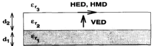
Fig. 2. Geometry of a 4-layer structure. Layer-0: PEC, Layer-3: half space, = 1, h = d l for
HED and HMD, h = d 2 / 2 for VED, z = 0.0 cm.
= 10, dl = 0.075 cm, er2 = 2 , d 2 = 0.15 cm,
GPOF method can be applied to the compkx coefficients of
e * j k z t z in all the Green’s functions except G;iF. Hence, the z-dependence in the closed-form Green’s functions becomes explicit and the testing procedure along the z-direction can be performed analytically for some testing functions like uniform and roof-top functions, which further improves the computational efficiency of using the closed-form Green’s functions in conjunction with the method of moments. Another technique, proposed here, to overcome the above mentioned difficulties is to interchange the order of integration (29),
provided that the basis and testing functions are so chosen that the involved integrals are uniformly convergent [ 121, and carrying out integration over z analytically for spectral domain representation of the Green’s function multiplied with the testing function. Next, the approximation method, GPOF, is applied to the resulting spectral domain function. For the inner product terms involving both the z and z’ integrations, these integrals can be performed analytically by using the procedure described above and subsequently applying the GPOF algorithm. Note that the spectral representations of the Green’s functions are exponential functions of z and z’, and this permits us to carry out z and z’ integrations analytically.
111. NUMERICAL RESULTS AND DISCUSSIONS The closed-form Green’s functions presented in Section I1 can be used for planar-layered geometries having an arbitrary number of layers with arbitrary layer parameters and general sources. In this section, a multilayer geometry is investigated for different types of sources and the Green’s functions ob- tained using the closed-forms (approximate) are compared with the exact Green’s functions, calculated by evaluating the corresponding Sommerfeld integrals numerically.
The geometry investigated in this paper consists of a sub- strate and a superstrate with three different dipoles (HED,
HMD, and VED) and modeled as a 4-layer structure with
the following parameters-layer-0: PEC, layer-3: half-space,
E , ~ = 10, E,, = 2, = 1, dl = 0.075 cm, d L =
0.15 cm, as shown in Fig. 2. The horizontal dipoles (HED
and HMD) are located at the air-dielectric interface ( h = &) and the vertical dipole is located in the middle of the top layer (h = &/2). In all three cases, the observation
points are chosen at the source plane ( z = z’ = 0.0 cm), which is the worst case as far as the convergence of the Green’s functions are concemed. Figs. 3-9 show the mag-
nitude of G&, $ G& dx, G$
,
Gcz,GF
,
G t z and GZm with respect to the distance k,p, which are obtained using both the closed-form representations and numerically evaluating theDURAL AND AKSUN: CLOSED-FORM GREEN’S FUNCTIONS FOR GENERAL SOURCES -12.0 1549 ~’ ’ -6.0 I I 0 Exact -8.0
h-
Apprx. -1 0.0 -1 2.0 -1 4.0 1 .o -1 6.0I
.
-3.0 -2.0 -1.0 0.0 log10(~0P )
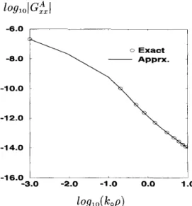
Fig. 3. Magnitude of the Green’s function for the vector potential, G,A,
for an HED. Layer-0: PEC, Layer-3: half space, t r l = 10, d l = 0.075 cm,
fr2 = 2 , d z = 0.15 cm, erg = I , h = dz, t = 0.0 cm, f = 1 GHz. -8.0 -9.0 -1 0.0 -1 1 .o 0 Exact Apprx. 0 Exact C
Fig. 4. Magnitude of the Green’s function for the vector potential,
G& d x , for an HED. Layer-0: PEC, Layer-3: half space, t r l = 10,di = 0.075 cm, t r 2 = 2,d2 = 0.15 cm, = I , h = d2, z = 0.0 cm, f = 1 GHz.
corresponding Sommerfeld integrals at a frequency of 1 GHz. In Fig. 4
I
j G t x dzl is given, instead of lGtxl, because the approximation is performed on G f z / k x . Fig. 10 shows the approximate and the exact Green’s functions, Gfz, calculated using the alternative form.In approximating the spectral domain Green’s functions using the GPOF, the choice of the number of samples used to represent a Green’s function in the spectral domain, the max- imum sampled value of k,, and the number of exponentials used to approximate the spectral domain Green’s functions
i 14.0
‘
0 Exact Apprx.I
12.0 ~1
10.0 8.01
6.0L 2
-3.0 -2.0 -1.0 0.0 1 .o log10(
IC0P )
Fig. 5. Magnitude of the Green’s function for the scalar potential, G p , for an HED. Layer-0: PEC, Layer-3: half space, e r l = 10,dl = 0.075 cm, t , , = 2 , d ~ = 0 . 1 5 c m , ~ , , = 1 , h = d ~ , ~ = O . O c m , f = I G H z . .~
1
0 Exact Apprx. -1 1 .o -1 2.0 -1 3.0 -1 4.0 -1 5.0 -3.0 -2.0 -1.0 0.0 1 .o k l l O ( ~ 0 P )Fig. 6 . Magnitude of the Green’s function for the vector potential, GFr,
for an HMD. Layer-0: PEC, Layer-3: half space, crl = 10, d l = 0.075 cm, e p 2 = 2 , d z = 0.15 cm, erg = I , h = d z , z = 0.0 cm, f = 1 GHz
depend on the parameters of the multilayer geometry, the type and the orientation of the dipole, and the Green’s function to be approximated. For example, it is observed that fewer sampling points, a fewer number of exponentials, and a smaller value of To are required for G!x than those required for
GF
.
This is because the vector potential contributes to the far field in the spatial domain; the major contributions in the spectral domain come from the region close to the origin. On the other hand, the scalar potential, which contributes to the near field dominantly, extends to larger values of k, in the spectral domain. As one of the contributions of this paper, the1550 IEEE TRANSACTIONS ON MICROWAVE THEORY AND TECHNIQUES, VOL. 43, NO. I, JULY 1995 10.0 0 Exact 9.0 8.0 7.0 6.0 5.0 -3.0 -2.0 -1.0 0.0 1.0
log,o(koP)
Fig. 7. Magnitude of the Green’s function for the scalar potential, GZm, for an HMD. Layer-0: PEC, Layer-3: half space, erl = IO, dl = 0.075 cm,
er2 = 2 , d ~ = O . l 5 c m , ~ , , = l , h = d ~ , z = O . O c m , f = l G H z .
-1 0.0
-1 1.0
-3.0 -2.0 -1.0 0.0 1.0
lOglo(k0P)
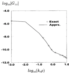
Fig. 8. Magnitude of the Green’s function for the vector potential, GP,, for a VED, traditional representation. Layer-0: PEC, Layer-3: half space,
e r l = 10, d l = 0.075 cm, tT2 = 2 , d 2 = 0.15 cm, era = 1, h = d 2 / 2 , z =
0.0 cm, f = 1 GHz.
approximation of the spectral domain Green’s functions by complex exponentials is performed by using the GPOF [17]. This technique is more robust and less noise sensitive [22] than the original and the least-square Prony’s methods. The robustness of the technique comes from the fact that it utilizes the singular value decomposition technique as an intermediate step to extract the complex exponentials, through which the number of exponentials used in the approximation can be chosen as the number of the most significant singular values either automatically or interactively. Consequently, the number
14.0 13.0 12.0 11.0 10.0 0 Exact 9.0 -3.0 -2.0 -1.0 0.0 1 .o
1
O Q l O(ko
P )
Fig. 9. Magnitude of the Green’s function for the scalar potential, GZe,
for a VED, traditional representation. Layer-0: PEC, Layer-3: half space, e r l = 10,dl = 0.075 cm, eV2 = 2, dZ = 0.15 cm, era = 1, h = dz12,z =
0.0 cm, f = 1 GHz.
-12.0
1
-3.0 -2.0 -1.0 0.0 1 .o
log10
(kop)
Fig. 10. Magnitude of the Green’s function for the vector potential, G!*,
for a VED, altemative representation. Layer-0: PEC, Layer-3: half space, eT1 = 10, d l = 0.075 cm, er2 = 2 , d2 = 0.15 cm, era = 1, h = d 2 / 2 , z = 0.0 cm, f = 1 GHz.
of exponentials chosen for each Green’s function in the examples given in this paper is different. For example, in the approximation of G t ! of Fig. 3, the number of exponentials,
the number of samples, and the maximum sampled value To
are chosen as 4 (including the direct term), 201, and 100, respectively, while the same parameters are chosen as 10 (including the direct term with no surface wave extraction), 401, and 100 for
Gg
of Fig. 5. It should be noted that the numbers given above are strongly dependent on the parameters of the geometry and the source.DURAL AND AKSUN: CLOSED-FORM GREEN’S FUNCTIONS FOR GENERAL SOURCES 1551
IV. CONCLUSION
In this work, a complete set of closed-form, spatial domain Green’s functions are provided in stratified media for general sources. The closed-form Green’s functions are obtained using the GPOF method, which is more robust and less noise sensitive than the original Prony’s and the least-square Prony’s methods. In addition, the Green’s functions are cast into a form to increase the numerical efficiency in the MOM applications. Numerical examples of the closed-form Green’s functions are given for a multilayer medium. The approximate Green’s functions are compared with the exact ones and very good agreement is observed.
APPENDIX
ALTERNATIVE FORM OF GREEN’S FUNCTION Since the vector and scalar potentials are not uniquely de- fined in stratified media, different sets of Green’s functions for the vector and scalar potentials are possible giving rise to many different MPIE formulations [18], [ 191. Among these Green’s functions, three useful choices referred as formulations A, B, and C, are given in [20]. In this paper, the formulation C is chosen as the altemative form of the Green’s function and
given here as
and Gqe.m as the Green’s function for the scalar potential
for both horizontal and vertical dipoles, Fig. 1. Note that the difficulties encountered in the traditional formulation due to
the difference between the scalar potentials of HED (HMD) and VED (VMD) are alleviated in this formulation. In the above form of the Green’s function, the terms associated with the horizontal dipoles (G:gF, Gf;“, G;;“, G;;“,
GF.“,
and G F , m ) remain the same as in the traditional form (2)-(7); two new entries, G:iF and Gf;“, are introduced and G:iF is modified for the vertical dipoles. For an 2-oriented HED and a z-oriented VED, the Green’s function components used with the alternative form are adopted to the formulation given in Section 11-A aswhere
G&,
Gkz are the alternative Green’s function compo- nents in the source layer and A;,u, B;l,v,‘E,
DZ are given in the (1 2)-( 17).ACKNOWLEDGMENT
Useful comments from Dr. E. Michielssen and D. Webb are gratefully acknowledged.
REFERENCES
N. K. Das and D. M. Pozar, “A spectral-domain Green’s function for multilayer dielectric substrates with application to multilayer transmis- sion lines,” IEEE Trans. Microwave Theory Tech., vol. MTl-35, pp. 326335, Mar. 1987.
F. Crog and D. M. Pozar, “Multifrequency operation of microstrip an- tennas using aperture coupled parallel resonators,”IEEE Trans. Antennas Propagat., vol. 40, pp. 1367-1374, Nov. 1992.
L. Barlatey, J. R. Mosig, and T. Sphicopoulos, “Analysis of stacked microstrip patches with mixed potential integral equation,” IEEE Trans. Antennas Propagat., vol. 18, pp. 608-615, May 1990.
A. N. Tulintseff, S. M. Ali, and J. A. Kong, “Input impedance of a probe fed stacked circular microstrip antenna,” IEEE Trans. Antennas Propagat., vol. 39, pp. 381-390, Mar. 1991.
K. R. Carver and J. W. Mink, “Microstrip antenna technology.” IEEE Trans. Antennas Propagat., vol. AP-29, pp. 2-24, Jan. 1981. D. R. Jackson and N. G. Alexopoulos,“Gain enhancement methods for printed antennas,’’ IEEE Trans. Antennas Propagat., vol. AP-33, pp. 976987, Sept. 1985.
C. I. G. Hsu, R. F. Harrington, K. A. Michalski, and D. Zheng,“Analysis of multiconductor transmission lines of arbitrary cross section in multi- layered uniaxial media,” IEEE Trans. Microwave Theory Tech., vol. 41, pp. 70-78, Jan. 1993
W. C. Chew, Waves and Fields in Inhomogeneous Media. New York: Van Nostrand Reinhold, 1990.
M. Gillick, I. D. Robertson, and J. S. Joshi,“Design analysis of novel coupling structures for multilayer MMIC’s,” IEEE Trans. Microwave Theory Tech., vol. 41, pp. 346349, Feb. 1993.
T. Tokumitsu, H. Hiraota, H. Makamoto, and T. Takenaka,“Multilayer MMIC using a 3 pmx 3-layer dielectric film structure,” in ZEEEM7T-S Int. Microwave Symp. Dig., 1990, pp. 831-834.
T. Hasegawa, S. Banba, H. Ogawa, and H. Nakamoto,“Characteristics of valley microstrip lines for use in multilayer MMIC’s,” lEEE Microwave Guided Wave Lett., vol. 1, Oct. 1991.
M. I. Aksun and R. Mittra, “Choices of expansion and testing functions for the method of moments applied to a class of electromagnetic problems,” lEEE Trans. Microwave Theory Tech., vol. 41, pp. 503-509, Mar. 1993.
Y. L. Chow, J. J. Yang, and D. F. Fang, and G. E. Howard, “Closed form spatial Green’s function for the thick substrate,” IEEE Trans. Mi,:rowave Theory Tech., vol. 39, pp. 588-592, Mar. 1991.
M. I. Aksun and R. Mittra, “Derivation of closed-fonn Green’s functions for a general microstrip geometry,” IEEE Trans. Microwave Theory Tech., vol. 40, pp. 2055-2062, Nov. 1992.
-, “Spurious radiation from microstrip interconnects,” IEEE Trans. Electromagn. Compat., vol. 35, pp. 148-158, May 1993.
S . L. Marple, Digital Spectral Analysis with Applications. Englewood Cliffs, NJ: Prentice Hall, 1987.
Y. Hua and T. K. Sarkar, “Generalized pencil-of-function method for extracting poles of an EM system from its transient response,” IEEE Trans. Antennas Propagat., vol. 37, pp. 229-234, Feb. 1989. A. Erteza and B. K. Park,“Nonuniqueness of resolution of Hertz vector in presence of a boundary, and a horizontal dipole problem,” IEEE Trans. Antennas Propagat., vol. AP-17, pp. 376378, May 1969. K. A. Michalski, “On the scalar potential of a point charge associ- ated with a time-harmonic dipole in a layered medium,” IEEE Trans. Antennas Propagat., vol. AP-35, pp. 1299-1301, Nov. 1987. K. A. Michalski and D. Zheng, “Electromagnetic scattering and radiation by surfaces of arbitrary shape in layered media, Part I: Theory,” IEEE Trans. Antennas Propagat., vol. 38, pp. 335-344, Mar. 1990. A. Sommerfeld, Partial Differential Equations in Physics. New York: Academic, 1949.
A. J. Mackay and A. McCowen, “An improved pecil-of-functions method and comparisons with traditional methods of pole extraction,” IEEE Trans. Antennas Propagat., vol. AP-35, pp. 4 3 5 4 4 1 , Apr. 1987.
1552 IEEE TRANSACTIONS ON MICROWAVE THEORY AND TECHNIQUES, VOL. 43, NO. 7 , JULY 1995
Giilbin Dural (S’84-M’89) received the B.S. and M.S. degrees in electrical and electronics engineer- ing from the Middle East Technical University, Ankara, Turkey, in 1981 and 1983, respectively, and the Ph.D. degree in electrical engineering from the Ohio State University, Columbus, OH, in 1988.
From 1981-1983, she was with the Middle East Technical University as a graduate assistant, and from 19861988 she was with the Ohio State Uni- versity ElectroScience Laboratory as a graduate research associate. Since 1989, she has been on the faculty of the department of electrical and electronics engineering at the Middle East Technical University, Ankara, Turkey, where she is currently an associate professor. Her research interests include the numerical methods for electromagnetics, microstrip antennas, microwave and millimeter-wave integrated circuits, and SAR and ISAR imaging techniques.
M. I. Aksun (M’92) received the B.S. and M.S. degrees in electrical and electronics engineering from the Middle East Technical University, Ankara, Turkey, in 1981 and 1983, respectively, and the Ph.D. degree in electrical and computer engineering from the University of Illinois at Urbana-Champaign in 1990.
From 1990-1992, he was a postdoctoral fellow at the Electromagnetic Communication Laboratory, University of Illinois at Urbana-Champaign. Since 1992, he has been on the faculty of the department of electrical and electronics engineering at Bilkent University, Ankara, Turkey, where he is currently an associate professor. His research interests include the numerical methods for electromagnetics, microstrip antennas and microwave and millimeter-wave integrated circuits.