ORIGINAL ARTICLE
The effect of cryogenic machining of S2 glass fibre
composite on the hole form and dimensional tolerances
Ugur Koklu1&Sezer Morkavuk1&Carol Featherston2&Malik Haddad3&David Sanders3&Muhammad Aamir4& Danil Yu Pimenov5&Khaled Giasin3
Received: 13 January 2021 / Accepted: 20 April 2021 # The Author(s) 2021
Abstract
S2 glass fibre reinforced epoxy composites are widely used in aeronautical applications owing to their excellent strength to weight ratio. Drilling glass fibres can be cumbersome due to their abrasive nature and poor thermal conductivity. Moreover, the use of conventional coolants is not desirable due to contamination and additional costs for cleaning the machine part. An alternative is to use environmentally friendly coolants such as liquid nitrogen (LN2) which have been previously employed in machining metals and composites. The current study investigates the effect of drilling S2 glass fibre composite in a bath of LN2. The study aims to evaluate the effect of spindle speed, feed rate and the presence of cryogenic cooling on the form and dimensional tolerances of the hole (hole size, circularity, cylindricity and perpendicularity). Design of experiments and analysis of variance (ANOVA) were used to determine the contribution of the input parameters on the analysed hole quality metrics. Results indicated that drilling S2 glass fibre in a cryogenic bath increased hole size significantly beyond the nominal hole diameter. The hole circularity and cylindricity were reduced compared to holes drilled under dry condition under all cutting parameters due to enhanced thermal stability during the drilling process. The current study aims to provide the scientific and industrial communities with the necessary knowledge on whether cryogenic bath cooling strategy provides better hole quality output compared to dry drilling and other cryogenic cooling strategies which were previously reported in the open literature. Keywords Hole size . circularity . Perpendicularity . Cylindricity . S2 glass fibre
1 Introduction
Glass fibre is the original fibre reinforcement of modern com-posites; it is mainly used as structural reinforcement in civil,
marine and aviation applications. Between 2020 and 2025, the market share of glass fibre composites will be the largest in terms of volume and value [1]. Glass fibres dominate the composite market due to their low cost and excellent
* Khaled Giasin [email protected] Ugur Koklu [email protected] Sezer Morkavuk [email protected] Carol Featherston [email protected] Malik Haddad [email protected] David Sanders [email protected] Muhammad Aamir [email protected] Danil Yu Pimenov [email protected] 1
Department of Mechanical Engineering, Faculty of Engineering, Karamanoglu Mehmetbey University, Karaman, Turkey
2
School of Engineering, Cardiff University, The Parade, Cardiff CF24 3AA, UK
3
School of Mechanical and Design Engineering, University of Portsmouth, Portsmouth PO1 3DJ, UK
4 School of Engineering, Edith Cowan University,
Joondalup, WA 6027, Australia
5 Department of Automated Mechanical Engineering, South Ural State
University, Lenin Prosp. 76, Chelyabinsk 454080, Russia
performance such as high strength, lightweight and durability. There are many types of glass fibres such as E, R and S/S2 and less known such as A, D and C. S-glass was originally devel-oped for military applications in the 1960s [2], Composites made from S2 glass was developed for commercial applica-tions in later stages as a lower-cost version of S-glass [2]. S-glass-based composites are used in aerospace applications due to the higher contents of silicon and aluminium oxides in the fibres which gives them greater elongation and lower density relative to other types of glass fibres. In, addition, S and S2 glass fibres have the highest tensile strength among all other types of glass fibres [3]. Therefore, they are attractive for use in aerospace applications because of their relative light weight, high strength and stiffness. For example, S2 glass fibre prepregs are bonded with aluminium metallic sheets to form a stack of hybrid metal-composite commercially known as GLARE® fibre metal laminates. GLARE® laminates are installed in the fuselage of the Airbus A380 due to their ex-cellent fatigue and impact resistance. Aeronautical structures are usually produced in large panels that require trimming to bring them to the right dimensions followed by drilling a large number of holes to install the fasteners used for the assembly of different structures together. Drilling glass fibre composites is challenging since the fibres have abrasive nature and the laminate have poor thermal conductivity. This in return would lead to rapid tool wear and lower hole quality due to increased chance for delamination and out-of-range hole tolerances. Moreover, it is estimated that poor connecting holes in aircraft structures account for up to 80% of fatigue cracks in the air-craft body [4,5]. Using oil-based or water-based coolants is an attractive choice to overcome tool wear and increase temper-atures during the machining process [6]. However, glass fibre composites are prone to moisture absorption which would reduce their strength and structural performance. An alterna-tive is to use a non-water-based or oil-based coolant such as liquid nitrogen and carbon dioxide which are also known as cryogenic coolants. The use of cryogenic coolants was mainly proposed for machining hard to cut materials such as titanium and steel alloys [7–9]. Cryogenic coolants are environmental-ly friendenvironmental-ly, providing a clean machining process without the need to dispose or handle the coolant waste [10]. Even the produced chip is free from oil and water contaminations, and therefore, the collected chips could be easily recycled [11].
There are a significant number of studies in the open liter-ature on drilling glass fibre composites. A table summary on previous research was previously reported by Giasin et al. [12]. Previous researchers studied the effects of cutting param-eters [13–17], drill type, geometry and coating [15,18–20] on developed cutting forces [21–24], tool wear [22,25,26] and several hole quality metrics such as delamination at exit and entry sides of the hole [18,24,27,28], surface roughness [14,
27,29], hole size and circularity [30–32]. Singh et al. [33] reported that the thrust force increased with the increase of
the feed rate and the drill point angle. Similar findings were also found in the work carried out by Işık et al. [34], Davim et al. [35, 36], Kilickap [37, 38] and Ramesh et al. [39]. Mohan et al. [40] reported that delamination is highly influ-enced by cutting parameters and workpiece thickness. They recommended using high cutting speed and low feed rate to minimise delamination at the exit side of the hole. Similar observations were reported by Kilickap [37]. However, con-tradicting results were reported by Palanikumar et al. [19] found that the delamination decreases as the spindle speed is increased. This might be due to the different tool geometry, cutting parameters or type of material machined in their stud-ies. Ranganathan et al. [41] found that the feed rate had more than three times the effect of cutting speed on the cutting forces, surface roughness and delamination. Similar results were also reported by Işık et al. [34] and Kilickap [37] and Sarma et al. [42] and Sureshkumar et al. [43]. Işık et al. [34] reported that increasing the number of drill flutes and point angle increased the delamination factor at the exit which was mainly due to increased chip load. Kilickap [44] and Palanikumar et al. [19] also reported that delamination is re-duced when the drill has a smaller point angle. Davim et al. [35] found that the drill type and its geometry had an impact on drilling performance of GFRP. Their results showed that the cutting pressure produced by Brad and Spur drills is lower than that produced by stub length drills; this in return pro-duced lower surface roughness and delamination. However, in another study by Latha et al. [36], it was reported that Brad and Spur drills produced higher thrust force than step and multi-facet drills. Mathew et al. [45] also reported that trepan-ning tools could reduce thrust force by up to 50% compared to twist drills when drilling GFRP, but hole accuracy must be carefully monitored by maintaining the accuracy of the cutting edges. In another study, Singh et al. [46] found that using four facet drills for drilling GFRP is not recommended due to very high cutting forces. In the other hand, 8 facet and jobber drills produced lower cutting forces. Abrao et al. also reported that the cutting tool geometry and material have significant effect on cutting forces and resulting delamination, a smaller the drill point angle and low feed rates were recommended for drilling CFRP and GFRP materials [47–49]. Rubio et al. [49] found that delamination is minimal when drilling GFRP at very high spindle speeds of 40,000 rpm, irrespectively of the feed speed employed. Davim et al. [35] also reported that the increase of the feed rate increased surface roughness while increasing the cutting speed decreased it. Similar trends were found in the work of Sarma et al. [42] which also reported that depth of cut shows only the limited effect in machining of GFRP compos-ites. Latha et al. [36] reported that the cutting forces increased with the increase of the drill diameter. Similarly, Bosco et al. [50] reported that the higher the drill diameter, the greater the delamination factor will be due to the larger contact area be-tween the cutting tool and the workpiece. Mehbudi et al. [23]
found that using ultrasonic assisted drilling of GFRP reduced cutting forces and delamination by up to 50% compared to conventional drilling. Mudhukrishnan et al. [38] found that the cutting tool material can significantly affect cutting forces during drilling of GFRP. Their results showed that HSS drills produced higher cutting forces and delamination in compari-son to tipped carbide and carbide drills due to lower hardness and faster tool wear. However, it was not reported whether all the drills had same geometry which might had some influence on the cutting forces. Similar results were observed by Arul et al. [20], which found that coated and uncoated HSS drills showed similar performance and faster tool wear compared to that observed using carbide drills. Indeed, Faria et al. [51] reported similar results where they found that HSS drills tended to produce higher cutting forces than coated and un-coated carbide drills. Moreover, the hole diameter and circu-larity decreased considerably when using HSS drill as the number of drilled increased which was due to rapid tool wear, while coated and uncoated carbide drills showed stable hole diameter when drilling up to 10,000 holes and stable hole circularity when drilling up to 24,000 holes. Kim et al. [52] reported that carbide drills produced oversized holes, while undersized holes were produced when using HSS drills. Sureshkumar et al. [43] found that the hole circularity and delamination increased with the feed rate increase. Vankanti et al. [30] also found that increasing cutting tool geometry such as its chisel edge and point angle in addition to the feed rate significantly increased hole circularity. The severity of damage in the hole is affected by the angle between fibre orientation and the cutting edge of the tool. The fibres are subjected to alternating torsion and compression prior shear-ing by the cuttshear-ing edges. That in return would produce an ellipse-like–shaped hole with its minor axis being same to the fibre direction [51]. Rubio et al. [32] found that the spindle speed was the main parameter that influences the hole circu-larity, while the point angle of the drill and feed rate had lesser effect. Other studies also reported that cryogenically treated cutting tools or using chilled air reduced delamination factor when drilling GFRP and CFRP [53,54]. After extensive re-view of literature, on drilling GFRP, it was found that there are no studies on the drilling of S or S2 glass fibre composites are available in the open literature except for one study conducted by Giasin et al. [55]. In their study, results showed that the cutting forces and hardness increased when drilling in a bath of LN2compared to dry drilling, while the surface roughness was reduced. Therefore, the current study aims to fulfil this gap and report on the effects of cutting parameters and the use of cryogenic liquid nitrogen cooling bath on the form and dimensional tolerances of holes in S2 glass fibre composite. In addition, holes machined in aeronautical structures must meet strict geometrical tolerances due to their direct impact on fatigue life of structure during their service. Indeed, accord-ing to historical data on fatigue in aircraft components, 55% of
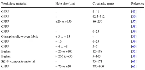
in-service failures in aircraft components occurs due to fatigue related to poor hole quality. Fastener holes tend to produce regions of stress concentrations at which fatigue cracks prop-agate [56]. Table1shows previous literature on hole form and dimensional tolerances reported when drilling CFRP and GFRP materials. The results indicated that achieving tight hole tolerances in composite material is a major challenge especially when no coolants are used. In addition, the litera-ture indicates that little attention is given to study the hole dimensional and geometric deviations after machining GFRPs. Therefore, the specific objective here is to determine the beneficial and adverse effects of drilling S2 glass fibre composite in a bath of LN2. Additionally, dry drilling tests were carried out to compare the hole quality output against results from cryogenic drilling tests. Statistical design of ex-periments was used to formulate the design study, and ANOVA and Pareto charts were used to further highlight the effect and percentage contribution of the cutting parameters and presence/absence of LN2coolant on the studied output parameters (hole size, circularity, cylindricity and perpendic-ularity). Improving the hole dimensional and geometrical tol-erances throughout the interior surface of the hole indicates high-quality holes [63], a pre-requisite in aerospace structural applications. The current study also aims to highlight the con-siderable contribution and drawbacks of cryogenic bath cooling as opposed to dry drilling of GFRP composites spe-cifically for use in aerospace applications.
2 Materials and method
This section presents the materials and method used. Subsection 2.1 presents work piece and cutting tool. Subsection 2.2 presents measurement of hole form, dimen-sional tolerances and hole inner surfaces.
2.1 Workpiece and cutting tool
An S2 glass fibre and FM94 adhesive epoxy workpiece was used in the current study for drilling tests. The workpiece was square shaped with 240-mm edge length and a thickness of 7.18 mm (54 prepregs with an approximate prepreg thickness of 0.133 mm) as shown in Fig.1a. The prepregs were made from S2 glass fibres embedded with FM94 adhesive film [64]. The S2 glass fibres were approximately 10 μm thick; the fabricated laminate was unidirectional (UD) with a symmetric stacking sequence of [0°/90°]27sas shown in Fig. 1a. The laminate was cured in the autoclave for approximately 300 min at a pressure of 6 bars [65] as shown in Fig. 1b. TiAlN-coated carbide twist drills with a diameter of∅6 mm were used. The drills had a point angle of 140° and a helix angle of 30° as shown in Fig.1c. Two sets of drilling exper-iments were carried out in the current study; the first set of
tests were carried out under dry conditions, and the second set of tests was carried out by placing the workpiece in a bath of liquid nitrogen as shown in Fig.1d.
The cutting parameters used in the current study are given in Table2. The choice of cutting parameters was based on previous literature and recommended cutting parameters by the cutting tool supplier. Three levels of feed rate ( f ) and spindle speed (n) and two levels for cooling (dry and cryogen-ic) were used. The aim was to form a full factorial L18(18 holes) design of experiment study to employ ANOVA statis-tical analysis to find the percentage contribution of the spindle speed, feed rate and presence/absence of coolant on the analysed hole metrics. A total of three drilling tests were car-ried out for cryogenic and drilling experiments; therefore, all
reported results thereafter represent the average of the three tests.
2.2 Measurement of hole form and dimensional
tolerances and hole inner surfaces
A CMM (coordinate measurement machine) was used to mea-sure the hole form and dimensional tolerances. The CMM used was a Mitutoyo Crysta-Apex S776 equipped with a Renishaw PH10MQ fitted with an AM2 adjustment module and a SP25M scanning probe system as shown in Fig.2. The measurements for hole size and circularity were taken at 1 mm below and above the top and bottom surfaces of the work-piece. The two positions are named top and bottom thereafter Table 1 Range of hole size an
circularity in previous studies on drilling composite materials
Workpiece material Hole size (μm) Circularity (μm) Reference
GFRP - 4–41 [43] GFRP - 42.5–312 [30] CFRP +20 to +950 80–250 [57] CFRP - - [58] CFRP - 6–25 [59] Glass/phenolic-woven fabric + 3 to + 13 - [31] CFRP − 10 6–25 [59] CFRP − 4 to +8 5–7 [60] E-glass − 20 to +100 12–188 [32] E-glass − 200 to +50 9–105 [51]
Si3N4 composite material - 73–171 [61]
CFRP − 70 to +20 780–900 [62]
Fig. 1 a) Workpiece fibre orientation and number of layers. b) Autoclave and manufacturing of the composite workpiece. c) Schematic of the drill bits used in the study. d) Setup of the workpiece inside the cryogenic bath inside the CNC machine [12]
in the manuscript discussion section. Additional measurement was taken at the middle of the workpiece in order to get mea-surements for the hole circularity and perpendicularity. After the CMM inspection, the holes were cross-sections from their centre and were observed using A Hitachi SU5000 field emis-sion SEM (scanning electron microscope) used to visualize the borehole surface quality.
3 Results and discussions
This section presents the results and discussion for the collect-ed hole metrics. Subsection 3.1 presents hole size and circu-larity analysis. Subsection 3.2 presents hole cylindricity and perpendicularity analysis and inspection of hole inner surfaces and post machining cutting tool conditions.
3.1 Hole size and circularity analysis
The spindle speed (n) and feed rate ( f ) cutting parameters play an important role to assess the hole quality during ma-chining [66]. Deviation from the nominal size is important for the performance of any machined part; therefore, the hole size
requires more attention as much as surface roughness. Previous study reported that during the drilling process the heat that flows into the workpiece from the cutting zone raises its temperature, and the resulting thermal distortions to the workpiece geometry [67], which is partially due to the differ-ent thermal expansion coefficidiffer-ent in the laminate due to dif-ferent fibre orientations. In the aerospace industry, holes must meet certain tolerances and standards it is desired that the holes be close to the nominal diameter for riveting [68,69]. Figure3shows the average hole size under different cutting parameters for dry and cryogenic conditions at top and bottom locations. Overall, the hole size deviation from the nominal size at top of the hole is more than at the bottom of the hole in dry drilling environment, while the holes obtained in the cryo-genic condition were found less deviated from the nominal size at the top as compared with the bottom side. Additionally, the difference between the entrance and exit diameters in holes drilled using cryogenic cooling were less than those drilled under dry conditions. This would indicate that using cryogenic cooling provide more consistency in hole size throughout its depth. Moreover, under dry conditions, the difference between the entrance and exit diameters tends to increase at the higher spindle speeds which is in agreement Table 2 Design of experiment
input parameters and their levels Factor Low level Medium level High level
Spindle speed (rpm) 3000 5000 7000
Feed rate (mm/min) 300 500 700
Cooling No (dry) Cryogenic bath of tool and workpiece
Fig. 2 Hole metrics measurement using CMM machine
with previous study on drilling composites [70].This is due to the rise in the drilling temperature that increases the mechan-ical abrasion onto the hole wall enlargement [70]. Nevertheless, the holes produced in dry drilling were closer to the drill nominal diameter than those obtained from the cryogenic drilling tests.
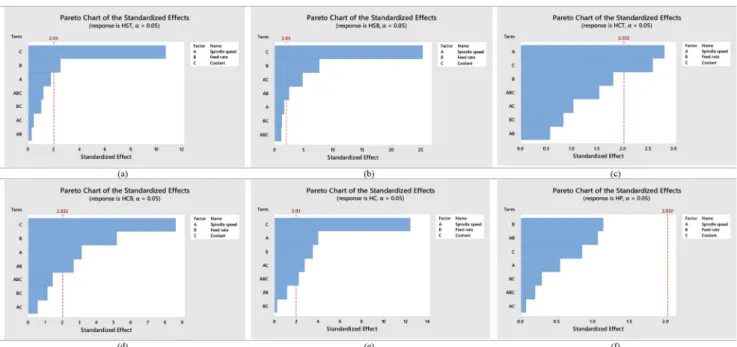
Overall, less deviation of holes from the nominal size was found with the increase in the feed rate in dry drilling. For hole size at the top, the minimum deviations of 6.0007 and 6.0213 mm and maximum values of 6.0147 and 6.0343 mm were found for dry and cryogenic conditions, respectively. The lowest n = 3000 rpm and highest fr= 700 mm/min were the reason for the minimum deviation, while the maximum values were caused at the moderate n = 5000 rpm and the lowest fr=300 mm/min. However, at the bottom of the hole size, the minimum deviated value for the dry condition was 5.9997 mm at the n of 5000 rpm and fr=700 mm/min, while for cryogenic condition, the minimum value of 6.0193 mm was obtained at the lowest n = 3000 rpm and fr=300 mm/min. Also, for dry conditions, the maximum deviated value of 6.0163 mm occurred when drilling at n = 3000 rpm and fr= 700 mm/min, while in the case of cryogenic conditions, the maximum deviated value of 6.0367 was observed at n = 7000 rpm and fr= 500 mm/min. The deviation of hole size due to the high n was expected due to the increase in the chatter vibration which might take an important role in the accuracy of the drilled hole size and causes instability of the cutting tool [66]. ANOVA results and Pareto chart given in Table3and Fig.5show that the use of cryogenic coolant had the most significant impact on hole size at top and bottom with 65% and 80%, respectively, followed by the feed, while the spindle speed did not seem to have any effect at all. The interaction between the cutting parameters and the coolant had a small impact on hole size in general.
Some researchers found that using flood coolants when drilling CFRP produced undersized holes [71]. On the con-trary, other studies reported that holes produced in CFRP un-der mist spray cooling were significantly oversized [63]. The oversized holes were caused by the lack of effective lubricat-ing and coollubricat-ing when uslubricat-ing mist spray coollubricat-ing which led to thermal expansion of the cutting tool and therefore oversized holes. On average, holes drilled under dry conditions pro-duced closest tolerances to the nominal dimension. This can be explained by the fact that the carbide tools— on average — has a lower thermal coefficient of expansion (5.2 × 10−6.C−1) [72] than the workpiece material (longitudinal direction, 3.9–
6.1 × 10−6.C−1; transverse direction, 26.2–55.2 × 10−6.C−1) [73], and as a result of cryogenic bath cooling, the workpiece contracts more than the cutting tool thus resulting in over cutting and thus oversized holes. In addition, when drilling under dry conditions, it is expected that cutting temperature will rise both the cutting tool and the workpiece leading to the expansion of the lamina; however, composites such as CFRP and GFRP have tendency to spring-back leading to shrinkage of drilled holes closer to their nominal diameter [74]. The current results disagree with previous studies [63,75–78] on drilling CFRP and GFRP laminates using through tool cryo-genic cooling which both reported reduced hole size when using cryogenic cooling compared to dry drilling. This could be attributed to the cooling strategy (i.e., cryogenic bath vs cryogenic through tool cooling) in which the later provides efficient cooling in terms of controlled coolant quantity and localisation on the hole cutting region and cutting tool. In another study, it was reported that indirect cryogenic cooling of composites provided better performance in terms of lowers thrust force and specific cutting energy consumption in com-parison to continuous cooling. The advantageous of this cooling technique is that it avoided workpiece hardening Fig. 3 Average hole size at the top and bottom of holes in dry and cryogenic conditions
caused by direct contact with cryogenic coolant [79]. Therefore, the literature appears to support the fact that the cooling strategy have significant and variable effect on the resulting hole and dimensional tolerances when drilling com-posites. However, it is difficult to compare the results like to like from those studies with the current study due to many variations such as the cutting tool type, geometry, material type and location of hole size measurement along the hole depth. However, a conclusion can be made here that using cryogenic bath cooling during drilling S2 glass fibre compos-ites would results in oversized holes compared to dry condi-tions or other cryogenic cooling strategies. This could be at-tributed to the increased hardness and cutting forces when using cryogenic bath cooling as reported in a previous study on drilling S2 glass fibre composites in a cryogenic bath [55]. Another reason for increased hole size using cryogenic bath creates an extremely low temperature environment for both the cutting tool and the workpiece which restricts the rise of cutting temperatures and prevents possible thermal expan-sions of both tool and workpiece, i.e., cutting occurs at− 196 °C or close to it. This was confirmed by Rodríguez et al. [77] which reported that under dry drilling, the temper-ature measured at the tool tip can be more than ten times higher than that when using cryogenic cooling. In addition, drilling at very low temperatures, the composite becomes
more brittle which causes a substantial increase in cutting forces, thereby increasing the probability oversized holes [80]. Another possible facto could be the tool wear and its effect on resulting hole quality; however, this does not apply in this study due to the limited number of holes drilled using each drill which did not promote significant tool wear as will be discussed in the later sections.
According to cutting tool manufactures, the aerospace industry’s requirements for hole size is to have minimal devi-ation from its nominal diameter to guarantee excellent rivet performance [81]. Generally, significantly oversized or under-sized holes are undesirable and would lead to rejection of the machined part. Riveted holes in aeronautical structures should comply with the recommended upper range of hole H9 (i.e., 0 to +30μm) tolerance as reported by aerospace manufacturers [81,82]. According to Brinksmeier et al. [83], those tolerances are needed for holes created in the composite structures that make up parts of the wing and tail of an aircraft. However, more relaxed hole sizes were reported to be as much as 250μm [84]. In addition, cutting tool manufacturers previous-ly reported that hole tolerances in aeronautical composite structures tended to have hole size deviations between ± 20 and ± 40μm [81,85]. In the current study, the deviation of hole size under cryogenic condition ranged between 21.33 and 34.33μm at top and between 19.67 μm and 36.67 μm at the Table 3 ANOVA data for measured output parameters
Hole size (top) Hole size (bottom) Circularity (top) Circularity (Bottom) Cylindricity Perpendicularity Source P value Contribution P value Contribution P value Contribution P value Contribution P value Contribution P value Contribution Model 0 80.95% 0 95.79% 0.017 56.22% 0 81.43% 0 86.66% 0.642 32.14% Blocks 0.226 1.74% 0.422 0.22% 0.085 6.82% 0.371 1.12% 0.876 0.10% 0.131 8.63% Linear 0 73.15% 0 89.30% 0.002 30.26% 0 66.10% 0 75.25% 0.482 9.15% Spindle speed 0.083 3.01% 0.11 0.58% 0.008 14.47% 0.004 7.26% 0 8.07% 0.591 2.13% Feed rate 0.017 5.19% 0 8.57% 0.077 7.11% 0 18.00% 0.001 6.46% 0.262 5.57% Coolant 0 64.95% 0 80.15% 0.014 8.68% 0 40.85% 0 60.71% 0.4 1.45% Two-way inter-actions 0.746 2.83% 0 5.58% 0.522 9.34% 0.038 10.36% 0.063 6.61% 0.669 11.56% Spindle speed*Feed rate 0.78 0.98% 0.019 1.70% 0.568 3.84% 0.012 8.26% 0.256 2.19% 0.293 10.31% Spindle speed*Coolant 0.656 0.48% 0 3.49% 0.309 3.13% 0.586 0.59% 0.009 4.24% 0.944 0.23% Feed rate*Coolant 0.309 1.36% 0.223 0.39% 0.408 2.37% 0.265 1.51% 0.808 0.17% 0.775 1.03% Three-way inter-actions 0.242 3.23% 0.259 0.69% 0.133 9.79% 0.159 3.86% 0.032 4.70% 0.842 2.80% Spindle speed*Feed rate*Coolant 0.242 3.23% 0.259 0.69% 0.133 9.79% 0.159 3.86% 0.032 4.70% 0.842 2.80% Error 19.05% 4.21% 43.78% 18.57% 13.34% 67.86% Total 100.00% 100.00% 100.00% 100.00% 100.00% 100.00%
bottom. Similarly, the deviation of hole size under dry condi-tion ranged between− 10.33 and 14.67 μm at top and between 16.33 and− 6.33 μm at the bottom. This means that the range of the hole size reported in this study were within the allow-able range required in aerospace applications and only under-sized holes must undergo an additional reaming process to enlarge them [68].
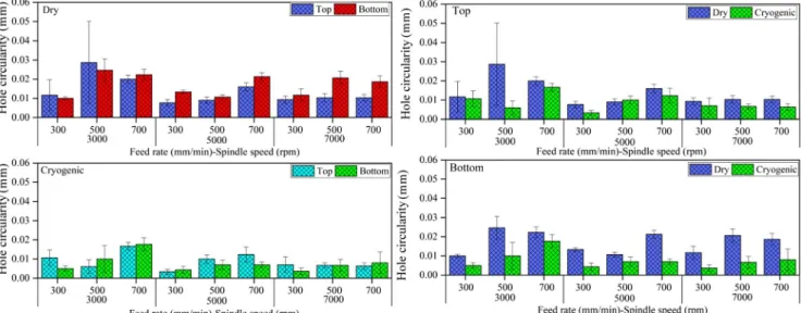
Figure4shows the average circularity for dry and cryogen-ic tests at top and bottom locations. The minimum hole circu-larity of 0.0077 mm and 0.0033 mm values for dry and cryo-genic conditions, respectively, were observed at the top of the hole size. For both the drilling conditions, these minimum values were obtained at the moderate n = 5000 rpm and the lowest fr= 300 mm/min. This indicates that lower feed rates produce holes with minimum circularity which was also re-ported in previous studies [60,76]. The increase in hole cir-cularity with increasing feed rate is related to the increase in the thrust force which increases the radial force that have direct influence on the circularity value [76,86]. The effect of feed rate can be seen more clearly in holes drilled under dry conditions due to higher distortions in the hole and drill which steadily deteriorates with an increment in depth below the hole entry surface [87]. The variation between hole circularity at top and bottom was greater in holes under dry conditions. Using coolant is known to decreases the frictional load be-tween the margin side of the drill and the machined hole wall; this in return would help the matrix in the composite to main-tain its original support and protection to the overall structural integrity of the holes during the drilling process. In return, the induced mechanical damage on the hole walls is reduced, and the cutting of the fibres occurs regularly which gives better dimensional accuracy [70]. While the maximum circularity was 0.0287 mm for dry and 0.0167 mm for cryogenic condi-tions were noted. These maximum values were the result of the lowest n = 3000 rpm with fr= 500 mm/min for dry drilling
and fr= 700 mm/min for cryogenic conditions. The maximum values due to high fr might be either due to the rise in cutting forces or the faster penetration of cutting tool that increased the hole deflection and vibrations in the cutting tool, hence the higher circularity [66,88]. However, at the bottom of the hole, the minimum and maximum circularity for the dry conditions was 0.0100 mm and 0.0247 mm, respectively. Both minimum and maximum values were obtained at n = 3000 rpm with fr= 300 mm/min and 500 mm/min, respectively. In the case of the cryogenic condi-tion, the minimum circularity of 0.0037 was noted at n = 7000 rpm and fr= 300 mm/min. Also, the maximum circu-larity of 0.0177 mm was observed at n of 3000 rpm and fr= 700 mm/min. It is also found that under dry drilling, the depth of deformation increases as the rate of feed increases. Table3 and Fig.5 shows that the spindle speed was the most dominant factor on circularity at the top, while the cryo-genic coolant had the highest impact on circularity at the bot-tom with 40.85%; this indicates that the cryogenic cooling could provide more stable circularity throughout the hole depth due to improved heat removal from the cutting zone. Similar results were reported by Shah et al. [89] which found that using cryogenic coolants reduced hole circularity when drilling metals over dry and flood cooling. The feed rate and spindle speed had a somewhat similar contribution on hole circularity at the bottom with 18% and 7.26%, respectively. However, the effects of the feed rate and the spindle speed on hole circularity are quite complicated. For example, the trends in circularity at the top and the bottom vary significantly when drilling metals. It is speculated that there non-linear variations in hole circularity are present in the hole due to other untested input parameters such as workpiece fixture or vibrations and deflections occurring in the drill and damping characteristics [90,91]. This was evident from the ANOVA analysis which showed the presence of a large error.
3.2 Hole cylindricity and perpendicularity analysis
Measuring the hole perpendicularity is a critical issue for aero-nautical structures since the structural loading could be trans-ferred through fuselage skin panels by riveted fastener holes at lap joints [92,93]. Holes with poor perpendicularity tended to minimise the area of contact between the rivet and the hole walls which leads to stress concentrations that ultimately re-duce the fatigue life of riveted structures [5]. Figure6shows the comparison of cylindricity and perpendicularity of S2/ FM94 glass fibre composites between dry and cryogenicconditions depending on cutting parameters. Considering all data, cylindricity increases with an increase in feed rate, but the same trend is not observed for spindle speed. It is well known that thrust forces increases linearly depending on an increase in the feed rate [55]. Vibration amplitude is a function of force and has a significant influence on circularity [94]. It was also noted that thrust force and torque cause compression, bending, and shear stresses and these loads give rise to cylindricity and deviation from nominal hole size [95]. When comparing the machining conditions, cryogenic ma-chining significantly improves cylindricity. Minimum hole Fig. 5 Pareto charts for a hole size at top b hole size at bottom c circularity at top d circularity at bottom e cylindricity f perpendicularity
Fig. 6 Average hole
perpendicularity and cylindricity of holes in dry and cryogenic conditions
cylindrically of 0.0047 mm was obtained at moderate n of 5000 rpm with frof 300 mm/min under cryogenic condition, while the maximum was 0.028 mm occurred at low n of 3000 rpm with frof 500 mm/min under dry condition. In the all cutting combination tested range, cryogenic machining provides less deviation for cylindricity. Ghasemi et al. [94] reported that higher temperatures occurred during drilling cause higher thermal stresses and cylindricity is directly af-fected by the thermal loads. In cryogenic conditions, liquid nitrogen would carry away heat during the drilling process, and less thermal damage occurs on the hole surface [96].
In drilling, perpendicularity is the deviation of the hole axis from the ideal cylinder axis with respect to the specified ref-erence point. This geometrical defect reduces the load-bearing capacity of bolted joints causing stress concentration around hole edges [97,98]. The results show perpendicularity in-creases depending on an increase in feed rate and spindle speed, but the influence of the feed rate is more dominant. This was also reported in past studies which indicated that perpendicularity is reduced when drilling at higher spindle speeds and lower feed rates [97,99–101]. The increase in perpendicularity depending on the cutting parameters can be explained by the same phenomenon in cylindricity, namely, tool vibration. On the other hand, it is seen that the cryogenic condition has hardly any effect on the perpendicularity. It is concluded from the results that cutting temperature is not ef-fective on perpendicularity contrary to other geometrical de-fects. This agrees with the previous study which found that machining coolants did not have an impact on the hole per-pendicularity; instead, it was the size and type of cutting tool used which influenced perpendicularity [102]. The minimum perpendicularity is 0.0853 mm obtained at moderate n of 5000 rpm with frof 300 mm/min under cryogenic condition. The ANOVA results and Pareto charts given in Table3and Fig.5show that the coolant was the most significant factor affecting the cylindricity of the hole with 60.71%, while both cutting parameters had a minor impact and somewhat equal. For perpendicularity, it appears that the ANOVA is unable to determine the effect of the input parameters. However, con-clusions can be made from analysing Fig.6. In addition, it was observed that the average perpendicularity of holes under cryogenic cooling was slightly lower than their counterparts under dry condition. It is worth noting that the hole perpen-dicularity data was inconsistent (i.e. poor repeatability), this would imply that additional factors that were not evaluated in the current study could have had an influence on hole perpen-dicularity [5]. For example, the hole position in the workpiece and the clamping setup, such factors will be investigated in a future study.
Previous study by Wang et al. [80] reported that optimum hole quality for composites is highly dependent on the tem-peratures at the cutting zone. Their study showed that main-taining the drilling temperature between the upper limit for
brittle deformation and the lowest limit of the glass transition zone temperature causes the interlaminar fracture toughness, anti-deformation capacity and interfacial shear strength of the composite to increase, thereby reducing the likelihood of dril-ling damage. The formation of higher temperatures during drilling process leads to undesirable thermal damage to the machined holes due to the thermal instability of resin matrix composites [80]. The interfacial shear strength is influenced by the increase in drilling temperatures such that when tem-perature in the cutting zone exceeds that of the resin glass transition temperature, the interfacial shear strength is reduced which have an unfavourable effect on the machining process [80]. Under cryogenic conditions, it can be safely assumed that the drilling temperature at the cutting zone is unlikely to reach the resin glass transition temperature. On the contrary, the low cryogenic temperature of liquid nitrogen might pro-mote increased interfacial shear strength and, therefore, might lead to the reduction in certain hole geometrical tolerances apart from the hole size due to brittle deformation. It is also known that the fracture toughness has direct impact on the exit delamination when drilling composites [80,103]. Indeed, in-crease the fracture toughness can improve the critical thrust force and reduce the probability of delamination [103]. It was previously reported that the fracture toughness of a composite increases exponentially with temperature. However, unrecov-ered deformation occurs in the glass transition temperature range which negatively influences drilling quality and leads to more defect on the borehole surfaces [80]. This in return might explain the somewhat higher circularity, perpendicular-ity and cylindricperpendicular-ity found in holes drilled under dry drilling conditions compared to those drilled under cryogenic conditions.
Figure7shows SEM images of inner borehole wall condi-tion. It was observed that the damages and distortions in the hole walls were influenced by the angle at which the cutting edge of the tool is cutting the fibres. The fibres were subjected to alternating torsion and compression prior shearing by the cutting edges. This in return would produce an elliptical hole where the minor axis of the ellipse is in the same direction of the fibres [51]. In addition, better surface finish was achieved when using cryogenic cooling which might have influenced the hole geometrical tolerances [55]. Evidence from SEM in-spection indicates that under dry drilling condition, the defects in the borehole walls are mainly characterised by the normal mechanical properties and fracture mechanisms of the carbon fibres themselves [70], while the damaging effect of the dril-ling process onto the hole walls is somewhat reduced under cryogenic cooling. It is important to note that under dry dril-ling condition, debris in the form of broken glass fibre are strongly present onto the hole walls, which supports the fact that powdery glass fibre chips tend to stick onto the cutting tool surface and the hole walls due to temperature rise at the cutting zone. With regard to the overall hole surface quality,
holes drilled using cryogenic cooling were found to have smoother surfaces than holes drilled under dry conditions using same cutting parameters [55].
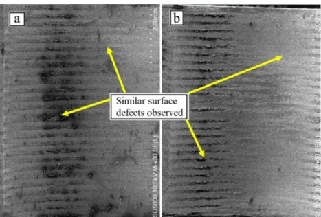
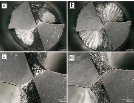
Figure8shows the morphologies of the hole walls drilled under dry and cryogenic conditions. It was observed that both drilling conditions exhibit similar damage features [55]. Enlargement of the severely damaged areas in the inspected holes indicates that the defects were mainly surface cavities and fibre pull-outs. Fibre bending was more common in holes drilled under dry conditions as shown in Fig.8a and c. The fibres which were cut by the cutting tool but remained intact with in the matrix appeared to be severely distorted, deformed and bent; the fibres were irregularly scattered and pointing out in different direction as shown in Fig.8a. This observation reflects that there was fierce frictional behaviour between the drill, the chip and the cut hole surface during the drilling operation [70], while the fibres found in holes drilled under cryogenic conditions appeared to be less damage and more uniform. It was observed that matrix loss was more severe in holes drilled under dry conditions due to thermal degradation of the epoxy matrix at high cutting temperatures, while under cryogenic conditions, the most noticeable form of damage was characterised by fibre pull outs as it can be seen in Fig.
8b and d. The extremely low temperatures induced by the cryogenic cooling during the drilling process appear to limit damages in fibre/matrix due to thermal degradation and high temperatures. It was also observed that under dry conditions, the fibre/matrix tended to stretch and overlap which could be due to rise in drilling temperatures and difference in the ther-mal conductivities of the fibres/matrix in different directions. This in return would explain the smaller hole size found in holes drilled under dry conditions. Moreover, the uncut fibres protruding outwards lack any form of support from the resin. Those extended fibres can easily break and separate from the hole surface and suppressed into the interlayers during the
subsequent drilling operation as it can be seen from Fig.8c and d.
Figure9shows the conditions of the cutting tools after the drilling tests. As seen from the images, minimal tool wear was formed in all the tools used in the drilling tests. Also, it can be Fig. 7 SEM images of holes inner
surfaces at 3000 rpm and 500 mm/min under a dry b cryogenic
Fig. 8 Morphologies of the hole walls drilled under a cryogenic bath at 3000 rpm and 700 mm/min b cryogenic bath at 5000 rpm and 500 mm/ min c dry condition at 5000 rpm and 700 mm/min d dry condition at 7000 rpm and 700 mm/min
seen that glass fibre dust powder scattered all over the drills. Figure8a and b shows that very limited signs of tool wear on the chisel edge and the cutting edges formed for both dry and cryogenic tests. This is mainly due to the high hardness of the carbide drills and TiAlN coating providing better resistance against abrasion. Moreover, absence of any significant tool wear could be due to the limited number of holes drilled using each tool. In addition, due the abrasive nature of glass fibres, it appears that excessive wear will form faster at the outer cor-ners of the drills as shown in Fig.8a and b. However, this claim must be confirmed by drilling additional holes, which will be carried out in a future study. No chipping was found on the cutting lips of the tools as shown in Fig.8c and d which means that the cutting parameters used in the study do not promote high thermal instability that could deteriorate the coating on the tool. Therefore, it is a conclusion on whether cryogenic cooling can prolong tool life cannot be concluded from this study, and further testing is required to investigate its impact on tool wear compared to dry drilling.
4 Conclusion
The current study investigated the effect of drilling holes in S2/FM94 glass fibre composite in a cryogenic bath of liquid nitrogen. The study aims to evaluate the effect of cryogenic cooling and cutting parameters (spindle speed and feed rate) on the hole and dimensional tolerances. The results from cryo-genic drilling tests are compared against results from dry dril-ling tests conducted under the same cutting parameters and using the same cutting tools. The following can be concluded:
& Oversized holes were produced in all holes at top and bottom locations under cryogenic conditions regardless of the cutting parameters used. ANOVA analysis showed that the coolant had the most significant contribution on hole size (65–80%) followed by a minor contribution by the feed rate.
& The deviation of hole size from the nominal hole diameter was greater when using cryogenic bath at top and bottom; this indicates that cryogenic bath might not be suitable for drilling S2 glass fibre composites. The deviation was greater than 20 μm which exceeds recommendation for hole size in aeronautical structures.
& Hole circularity found under cryogenic bath was always less than their counterparts under the dry condition at top and bottom locations. It was also found that in general, hole circularity at the bottom was greater than at top under dry conditions especially at higher cutting parameters, while for cryogenic tests, hole circularity at top and bot-tom were relatively similar which indicates that cryogenic bath is effective in minimising hole circularity, especially at high cutting parameters.
& Hole circularity at the top was influenced by the feed rate and cooling, while at the bottom, the coolant showed the highest influence with 40% followed by the spindle speed and feed rate, respectively.
& Hole cylindricity was significantly reduced under cryo-genic conditions and was not highly affected by the in-crease in the feed rate similar to what was observed in dry drilling tests. ANOVA results showed that cryogenic cooling was the major factor affecting cylindricity with 60%.
Fig. 9 Post machining tool condition under a and c dry b and d cryogenic conditions
& Hole perpendicularity in dry and cryogenic tests was sim-ilar; the use of cryogenic cooling did not seem to have any impact. However, it was observed that in general, the av-erage perpendicularity in cryogenic tests was slightly low-er than their countlow-erparts in dry tests.
& Considering that producing holes with eliminated/reduced circularity, cylindricity and perpendicularity, cryogenical-ly assisted drilling of S2 glass fibre composite can be a preferred approach for aerospace applications.
Acknowledgements The authors would like to sincerely thank Mr. William Keeble for assistance with the measurements of hole metrics. Author contribution All the authors have contributed equally to the pro-duction of the present paper.
Data availability All data that support the findings of this study are avail-able from the corresponding author upon reasonavail-able request.
Declarations
Conflict of interest The authors declare no competing interests. Open Access This article is licensed under a Creative Commons Attribution 4.0 International License, which permits use, sharing, adap-tation, distribution and reproduction in any medium or format, as long as you give appropriate credit to the original author(s) and the source, pro-vide a link to the Creative Commons licence, and indicate if changes were made. The images or other third party material in this article are included in the article's Creative Commons licence, unless indicated otherwise in a credit line to the material. If material is not included in the article's Creative Commons licence and your intended use is not permitted by statutory regulation or exceeds the permitted use, you will need to obtain permission directly from the copyright holder. To view a copy of this licence, visithttp://creativecommons.org/licenses/by/4.0/.
References
1. marketsandMarkets™ (2020) Impact of COVID-19 on global composites market, Global Forecast to 2025. [cited 2020 19/08]. Available from: https://www.marketsandmarkets.com/Market-Reports/composite-market-200051282.html
2. Gudmundsson S (2013) General aviation aircraft design: applied methods and procedures. Butterworth-Heinemann
3. Kinsella M, Murray D, Crane D, Mancinelli J, Kranjc M (2001) Mechanical properties of polymeric composites reinforced with high strength glass fibers. in International SAMPE Technical Conference
4. Yuan P, Lai T, Li Y, Han W, Lin M, Zhu Q, Liu Y, Shi Z (2016) The attitude adjustment algorithm in drilling end-effector for avi-a t io n . A d v Me c h Eng 8(1) . https://doi.org/10.1177/ 1687814016629348
5. Giasin K (2018) The effect of drilling parameters, cooling tech-nology, and fiber orientation on hole perpendicularity error in fiber metal laminates. Int J Adv Manuf Technol 97(9-12):4081–4099.
https://doi.org/10.1007/s00170-018-2241-1
6. Hocheng H (2011) Machining technology for composite mate-rials: principles and practice. Elsevier
7. Pimenov DY, Mia M, Gupta MK, Machado AR, Tomaz ÍV, Sarikaya M, Wojciechowski S, Mikolajczyk T, Kapłonek W (2021) Improvement of machinability of Ti and its alloys using cooling-lubrication techniques: a review and future prospect. J Mater Res Technol 11:719–753.https://doi.org/10.1016/j.jmrt. 2021.01.031
8. Sarikaya M, Gupta MK, ItaloTomaz M, Danish M, Mia S, Rubaieef M, Jamil DYP, Khanna N (2020) Cooling techniques to improve the machinability and sustainability of light-weight alloys: a state-of-the-art review. J Manuf Process 62:179–201.
https://doi.org/10.1016/j.jmapro.2020.12.013
9. Balan ASS, Chidambaram K, Kumar AV, Krishnaswamy H, Pimenov DY, Giasin K, Nadolny K (2021) Effect of cryogenic grinding on fatigue life of additively manufactured maraging steel. Materials 14(5):1245.https://doi.org/10.3390/ma14051245
10. Yildiz Y, Nalbant M (2008) A review of cryogenic cooling in machining processes. Int J Mach Tools Manuf 48(9):947–964.
https://doi.org/10.1016/j.ijmachtools.2008.01.008
11. Pušavec F, Stoić A, Kopač J (2009) The role of cryogenics in machining processes. Tehnički vjesnik 16(4):3–10
12. Giasin K, Barouni A, Dhakal HN, Featherson C, Redouane Z, Morkavuk S, Koklu U (2020) Microstructural investigation and hole quality evaluation in S2/FM94 glass-fibre composites under dry and cryogenic conditions. J Reinf Plast.https://doi.org/10. 1177/0731684420958479
13. Beumler T (2004) Flying GLARE: A contribution to aircraft cer-tification issues in strength properties in non-damaged and fatigue damaged GLARE structures. Delft University Press
14. Rezende BA, Silveira ML, Vieira LM, Abrão AM, Faria PEd, Rubio JCC (2016) Investigation on the effect of drill geometry and pilot holes on thrust force and burr height when drilling an aluminium/PE sandwich material. Materials 9(9):774.https://doi. org/10.3390/ma9090774
15. Senthilkumar BMA (2016) Mechanical and machinability charac-teristics of fiber metal laminates. LAP Lambert Academic Publishing 60
16. Khashaba U, El-Sonbaty I, Selmy A, Megahed A (2012) Drilling analysis of woven glass fiber-reinforced/epoxy composites. J Compos Ma ter 47: 191–205. https: //doi .org/10.1177/ 0021998312438620
17. Krishnaraj V (2008) Effects of drill points on glass fibre reinforced plastic composite while drilling at high spindle speed. In: Proceedings of the World Congress on Engineering. London-U.K 18. Kim GW, Lee KY (2005) Critical thrust force at propagation of delamination zone due to drilling of FRP/metallic strips. Compos Struct 69(2):137–141.https://doi.org/10.1016/j.compstruct.2004. 06.013
19. Palanikumar K, Rubio JC, Abrao A, Correia AE, Davim JP (2008) Influence of drill point angle in high speed drilling of glass fiber reinforced plastics. J Compos Mater 42(24):2585–2597.https:// doi.org/10.1177/0021998308096322
20. Arul S, Vijayaraghavan L, Malhotra S, Krishnamurthy R (2006) Influence of tool material on dynamics of drilling of GFRP com-posites. Int J Adv Manuf Technol 29(7-8):655–662.https://doi. org/10.1007/s00170-005-2581-5
21. Kim D, Ramulu M (2007) Study on the drilling of titanium/ graphite hybrid composites. J Eng Mater Technol 129(3):390– 396.https://doi.org/10.1115/1.2744397
22. Sánchez Carrilero M, Álvarez M, Ares E, Astorga J, Cano M, Marcos M (2006) Dry drilling of fiber metal laminates CF/ AA2024. A preliminary study. in Materials science forum. Trans Tech Publ.https://doi.org/10.4028/www.scientific.net/MSF.526. 73
23. Mehbudi P, Baghlani V, Akbari J, Bushroa A, Mardi N (2013) Applying ultrasonic vibration to decrease drilling-induced delam-ination in GFRP laminates. Procedia Cirp 6:577–582.https://doi. org/10.1016/j.procir.2013.03.097
24. Khashaba U, El-Sonbaty I, Selmy A, Megahed A (2010) Machinability analysis in drilling woven GFR/epoxy composites: part I–Effect of machining parameters. Compos A: Appl Sci Manuf 41(3):391–400. https://doi.org/10.1016/j.compositesa. 2009.11.006
25. Coesel JFW (1994) Drilling of fibre-metal laminates, in faculty of aerospace engineering. Delft University of Technology, p 63 26. Tyczynski P, Lemanczyk J, Ostrowski R (2014) Drilling of CFRP,
GFRP, glare type composites. Aircr Eng Aerosp Technol 86(4): 312–322.https://doi.org/10.1108/AEAT-10-2012-0196
27. Zitoune R, Collombet F, Lopez GH (2008) Experimental and analytical study of the influence of HexFit® glass fibre composite manufacturing process on delamination during drilling. Int J Mach Mach Mater 3(3-4):326–342.https://doi.org/10.1504/IJMMM. 2008.020967
28. Lin S-C, Shen J-M (1999) Drilling unidirectional glass fiber-reinforced composite materials at high speed. J Compos Mater 33(9):827–851.https://doi.org/10.1177/002199839903300903
29. Pawar OA, Gaikhe YS, Tewari A, Sundaram R, Joshi SS (2015) Analysis of hole quality in drilling GLARE fiber metal laminates. Compos Struct 123:350–365. https://doi.org/10.1016/j. compstruct.2014.12.056
30. Vankanti VK, Ganta V (2014) Optimization of process parameters in drilling of GFRP composite using Taguchi method. J Mater Res Technol 3(1):35–41.https://doi.org/10.1016/j.jmrt.2013.10.007
31. Velayudham A, Krishnamurthy R, Soundarapandian T (2005) Evaluation of drilling characteristics of high volume fraction fibre glass reinforced polymeric composite. Int J Mach Tools Manuf 45(4-5):399–406.https://doi.org/10.1016/j.jmrt.2013.10.007
32. Rubio JCC, da Silva LJ, de Oliveira Leite W, Panzera TH, Ribeiro Filho SLM, Davim JP (2013) Investigations on the drilling process of unreinforced and reinforced polyamides using Taguchi method. Compos Part B 55:338–344. https://doi.org/10.1016/j. compositesb.2013.06.042
33. Singh I, Bhatnagar N, Viswanath P (2008) Drilling of uni-directional glass fiber reinforced plastics: experimental and finite element study. Mater Des 29(2):546–553.https://doi.org/10.1016/ j.matdes.2007.01.029
34. Işık B, Ekici E (2010) Experimental investigations of damage analysis in drilling of woven glass fiber-reinforced plastic com-posites. Int J Adv Manuf Technol 49(9-12):861–869.https://doi. org/10.1007/s00170-009-2440-x
35. Davim JP, Reis P, Antonio CC (2004) Experimental study of drilling glass fiber reinforced plastics (GFRP) manufactured by hand lay-up. Compos Sci Technol 64(2):289–297.https://doi. org/10.1016/S0266-3538(03)00253-7
36. Latha B, Senthilkumar V, Palanikumar K (2011) Influence of drill geometry on thrust force in drilling GFRP composites. J Reinf Plast Compos 30(6):463–472. https://doi.org/10.1177/ 0731684410397681
37. Kilickap E (2010) Investigation into the effect of drilling parame-ters on delamination in drilling GFRP. J Reinf Plast Compos 29(23):3498–3503.https://doi.org/10.1177/0731684410386271
38. Mudhukrishnan M, Hariharan P, Palanikumar K (2020) Measurement and analysis of thrust force and delamination in drilling glass fiber reinforced polypropylene composites using different drills. Measurement 149:106973.https://doi.org/10. 1016/j.measurement.2019.106973
39. Ramesh B, Elayaperumal A (2012) Optimization of process pa-rameter levels during drilling high fiber volume fraction nonlaminated GFRP polymeric composites. Int J Sci Eng Appl 1(2):120–126.https://doi.org/10.7753/IJSEA0102.1007
40. Mohan N, Kulkarni S, Ramachandra A (2007) Delamination analysis in drilling process of glass fiber reinforced plastic (GFRP) composite materials. J Mater Process Technol 186(1-3): 265–271.https://doi.org/10.1016/j.jmatprotec.2006.12.043
41. Ranganathan S, Senthilvelan T, Gopalakannan S (2012) Multiple performance optimization in drilling of GFRP composites using grey analysis. In: IEEE-International Conference On Advances In Engineering, Science And Management (ICAESM-2012). IEEE. 42. Sarma P, Karunamoorthy L, Palanikumar K (2009) Surface roughness parameters evaluation in machining GFRP composites by PCD tool using digital image processing. J Reinf Plast Compos 28(13):1567–1585.https://doi.org/10.1177/0731684408089858
43. Sureshkumar M, Lakshmanan D, Murugarajan A (2014) Experimental investigation and mathematical modelling of dril-ling on GFRP composites. Mater Res Innov 18:S1–S97.https:// doi.org/10.1179/1432891713Z.000000000361
44. Kilickap E (2010) Optimization of cutting parameters on delami-nation based on Taguchi method during drilling of GFRP com-posite. Expert Syst Appl 37(8):6116–6122.https://doi.org/10. 1016/j.eswa.2010.02.023
45. Mathew J, Ramakrishnan N, Naik NK (1999) Investigations into the effect of geometry of a trepanning tool on thrust and torque during drilling of GFRP composites. J Mater Process Technol 91(1):1–11.https://doi.org/10.1016/S0924-0136(98)00416-6
46. Singh I, Bhatnagar N (2006) Drilling of uni-directional glass fiber reinforced plastic (UD-GFRP) composite laminates. Int J Adv Manuf Technol 27(9-10):870–876. https://doi.org/10.1007/ s00170-004-2280-7
47. Abrão AM, Rubio JCC, Faria PE, Davim JP (2008) The effect of cutting tool geometry on thrust force and delamination when dril-ling glass fibre reinforced plastic composite. Mater Des 29(2): 508–513.https://doi.org/10.1016/j.matdes.2007.01.016
48. Gaitonde VN, Karnik SR, Rubio JC, Correia AE, Abrão AM, Davim JP (2008) Analysis of parametric influence on delamina-tion in high-speed drilling of carbon fiber reinforced plastic com-posites. J Mater Process Technol 203(1):431–438.https://doi.org/ 10.1016/j.jmatprotec.2007.10.050
49. Campos Rubio J, Abrao AM, Faria PE, Correia AE, Davim JP (2008) Effects of high speed in the drilling of glass fibre reinforced plastic: evaluation of the delamination factor. Int J Mach Tools Manuf 48(6):715–720. https://doi.org/10.1016/j.ijmachtools. 2007.10.015
50. Bosco MAJ, Palanikumar K, Prasad BD, Velayudham A (2013) Influence of machining parameters on delamination in drilling of GFRP-armour steel sandwich composites. Procedia Engineering 51:758–763.https://doi.org/10.1016/j.proeng.2013.01.108
51. Faria P, Campos Rubio J, Abrao A, Davim J (2009) Dimensional and geometric deviations induced by drilling of polymeric com-posite. J Reinf Plast Compos 28(19):2353–2363.https://doi.org/ 10.1177/0731684408092067
52. Kim D, Ramulu M (2004) Drilling process optimization for graph-ite/bismaleimide–titanium alloy stacks. Compos Struct 63(1): 101–114.https://doi.org/10.1016/S0263-8223(03)00137-5
53. Arun K, Ramesh Kannan C, Stalin B (2020) The effect of cryo-genically treated drilling tool on GFRP composite drilling holes-a comparative study. Materials Today: Proceedings 33:4362–4367.
https://doi.org/10.1016/j.matpr.2020.07.579
54. Abish J, Samal P, Narenther M, Kannan C, Balan A (2018) Assessment of drilling-induced damage in CFRP under chilled air environment. Mater Manuf Process 33(12):1361–1368.
https://doi.org/10.1080/10426914.2017.1415452
55. Giasin K, Barouni A, Dhakal HN, Featherson C, Redouane Z, Morkavuk S, Koklu U (2020) Microstructural investigation and hole quality evaluation in S2/FM94 glass-fibre composites under dry and cryogenic conditions. J Reinf Plast Compos 40:273–293.
56. Sun D, Lemoine P, Keys D, Doyle P, Malinov S, Zhao Q, Qin X, Jin Y (2018) Hole-making processes and their impacts on the microstructure and fatigue response of aircraft alloys. Int J Adv Manuf Technol 94(5-8):1719–1726. https://doi.org/10.1007/ s00170-016-9850-3
57. Krishnaraj V, Prabukarthi A, Ramanathan A, Elanghovan N, Senthil Kumar M, Zitoune R, Davim JP (2012) Optimization of machining parameters at high speed drilling of carbon fiber rein-forced plastic (CFRP) laminates. Compos Part B 43(4):1791– 1799.https://doi.org/10.1016/j.compositesb.2012.01.007
58. Ameur M, Habak M, Kenane M, Aouici H, Cheikh M (2017) Machinability analysis of dry drilling of carbon/epoxy compos-ites: cases of exit delamination and cylindricity error. Int J Adv Manuf Technol 88(9-12):2557–2571.https://doi.org/10.1007/ s00170-016-8967-8
59. Zitoune R, Krishnaraj V, Collombet F (2010) Study of drilling of composite material and aluminium stack. Compos Struct 92(5): 1246–1255.https://doi.org/10.1016/j.compstruct.2009.10.010
60. Alizadeh Ashrafi S, Miller PW, Wandro KM, Kim D (2016) Characterization and effects of fiber pull-outs in hole quality of carbon fiber reinforced plastics composite. Materials 9(10):828.
https://doi.org/10.3390/ma9100828
61. Gowda BU, Ravindra H, Prakash GN, Nishanth P, Ugrasen G (2015) Optimization of process parameters in drilling of epoxy Si3N4 composite material. Materials Today: Proceedings 2(4-5): 2852–2861.https://doi.org/10.1016/j.matpr.2015.07.300
62. Angelone R, Caggiano A, Improta I, Nele L, Teti R (2019) Characterization of hole quality and temperature in drilling of Al/CFRP stacks under different process condition. Procedia CIRP 79:319–324.https://doi.org/10.1016/j.procir.2019.02.074
63. Xia T, Kaynak Y, Arvin C, Jawahir I (2016) Cryogenic cooling-induced process performance and surface integrity in drilling CFRP composite material. Int J Adv Manuf Technol 82(1-4): 605–616.https://doi.org/10.1007/s00170-015-7284-y
64. Vlot A, Gunnink JW (2001) Fibre metal laminates: an introduc-tion. Springer
65. Botelho EC, Silva RA, Pardini LC, Rezende MC (2006) A review on the development and properties of continuous fiber/epoxy/alu-minum hybrid composites for aircraft structures. Mater Res 9(3): 247–256.https://doi.org/10.1590/S1516-14392006000300002
66. Kurt M, Kaynak Y, Bagci E (2008) Evaluation of drilled hole quality in Al 2024 alloy. Int J Adv Manuf Technol 37(11-12): 1051–1060.https://doi.org/10.1007/s00170-007-1049-1
67. Bono M, Ni J (2001) The effects of thermal distortions on the diameter and cylindricity of dry drilled holes. Int J Mach Tools Manuf 41(15):2261–2270. https://doi.org/10.1016/S0890-6955(01)00047-5
68. Giasin K, Hawxwell J, Sinke J, Dhakal H, Köklü U, Brousseau E (2020) The effect of cutting tool coating on the form and dimen-sional errors of machined holes in GLARE® fibre metal lami-nates. Int J Adv Manuf Technol 107:1–16. https://doi.org/10. 1007/s00170-020-05211-2
69. Aamir M, Tolouei-Rad M, Giasin K, Nosrati A (2019) Recent advances in drilling of carbon fiber–reinforced polymers for aero-space applications: a review. Int J Adv Manuf Technol 105(5-6): 2289–2308.https://doi.org/10.1007/s00170-019-04348-z
70. Xu J, Ji M, Chen M, El Mansori M (2020) Experimental investi-gation on drilling machinability and hole quality of CFRP/ Ti6Al4V stacks under different cooling conditions. Int J Adv Manuf Technol 109(5):1527–1539. https://doi.org/10.1007/ s00170-020-05742-8
71. Shyha I, Soo SL, Aspinwall D, Bradley S, Perry R, Harden P, Dawson S (2011) Hole quality assessment following drilling of metallic-composite stacks. Int J Mach Tools Manuf 51(7-8):569– 578.https://doi.org/10.1016/j.ijmachtools.2011.04.007
72. Liu K (2012) Tungsten carbide: processing and applications. BoD–Books on Demand
73. Giasin K, Ayvar-Soberanis S, Hodzic A (2016) Evaluation of cryogenic cooling and minimum quantity lubrication effects on machining GLARE laminates using design of experiments. J Clean Prod 135:533–548.https://doi.org/10.1016/j.jclepro.2016. 06.098
74. Shokrani A, Leafe H, Newman ST (2019) Cryogenic drilling of carbon fibre reinforced plastic with tool consideration. Procedia CIRP 85:55–60.https://doi.org/10.1016/j.procir.2019.10.008
75. Giasin K, Dad A, Brousseau E, Pimenov D, Mia M, Morkavuk S, Koklu U (2021) The effects of through tool cryogenic machining on the hole quality in GLARE® fibre metal laminates. J Manuf Process 64:996–1012.https://doi.org/10.1016/j.jmapro.2021.02. 010
76. Nagaraj A, Uysal A, Jawahir I (2020) An Investigation of process performance when drilling carbon fiber reinforced polymer (CFRP) composite under dry, cryogenic and MQL environments. Procedia Manufacturing 43:551–558.https://doi.org/10.1016/j. promfg.2020.02.165
77. Rodríguez A, Calleja A, de Lacalle LNL, Pereira O, Rubio-Mateos A, Rodríguez G (2021) Drilling of CFRP-Ti6Al4V stacks using CO2-cryogenic cooling. J Manuf Process 64:58–66.https:// doi.org/10.1016/j.jmapro.2021.01.018
78. Kumar D, Gururaja S, Jawahir I (2020) Machinability and surface integrity of adhesively bonded Ti/CFRP/Ti hybrid composite lam-inates under dry and cryogenic conditions. J Manuf Process 58: 1075–1087.https://doi.org/10.1016/j.jmapro.2020.08.064
79. Iqbal A, Zhao G, Zaini J, Gupta MK, Jamil M, He N, Nauman MM, Mikolajczyk T, Pimenov DY (2021) Between-the-holes cryogenic cooling of the tool in hole-making of Ti-6Al-4V and CFRP. Materials 14:795.https://doi.org/10.3390/ma14040795
80. Wang H, Zhang X, Duan Y (2018) Effects of drilling area tem-perature on drilling of carbon fiber reinforced polymer composites due to temperature-dependent properties. Int J Adv Manuf Technol 96(5):2943–2951. https://doi.org/10.1007/s00170-018-1810-7
81. Giasin K (2017) Machining fibre metal laminates and Al2024-T3 aluminium alloy, University of Sheffield
82. Gardiner G (2014) Hole quality defined, compositesworld 83. Brinksmeier E, Janssen R (2002) Drilling of multi-layer composite
materials consisting of carbon fiber reinforced plastics (CFRP), titanium and aluminum alloys. CIRP Ann 51(1):87–90.https:// doi.org/10.1016/S0007-8506(07)61472-3
84. Everson CE, Hoessein Cheraghi S (1999) The application of acoustic emission for precision drilling process monitoring. Int J Mach Tools Manuf 39(3):371–387.https://doi.org/10.1016/ S0890-6955(98)00054-6
85. SANDVIK (2011) Improved hand-held hole making in compos-ites.http://www.sandvik.coromant.com
86. Chandrasekharan V (1997) A model to predict the three-dimensional cutting force system for drilling with arbitrary point geometry.
87. Chakravarthy VVK, Rajmohan T, Vijayan D, Palanikumar K (2021) Sustainable drilling of nano SiC reinforced Al matrix com-posites using MQL and cryogenic cooling for achieving the better surface integrity. Silicon. https://doi.org/10.1007/s12633-021-00977-w
88. Giasin K, Ayvar-Soberanis S (2017) An Investigation of burrs, chip formation, hole size, circularity and delamination during dril-ling operation of GLARE using ANOVA. Compos Struct 159: 745–760.https://doi.org/10.1016/j.compstruct.2016.10.015
89. Shah P, Khanna N, Chetan (2020) Comprehensive machining analysis to establish cryogenic LN2 and LCO2 as sustainable cooling and lubrication techniques. Tribol Int 148:106314.
90. Abdelhafeez AM, Soo SL, Aspinwall DK, Dowson A, Arnold D (2015) Burr formation and hole quality when drilling titanium and aluminium alloys. Procedia CIRP 37:230–235
91. Giasin K, Hodzic A, Phadnis V, Ayvar-Soberanis S (2016) Assessment of cutting forces and hole quality in drilling Al2024 aluminium alloy: experimental and finite element study. Int J Adv Manuf Technol 87(5-8):2041–2061.https://doi.org/10.1007/ s00170-016-8563-y
92. Bickford J (1998) Handbook of bolts and bolted joints. CRC press.
93. Gao Y, Wu D, Dong Y, Ma X, Chen K (2017) The method of aiming towards the normal direction for robotic drilling. Int J Precis Eng Manuf 18(6):787–794. https://doi.org/10.1007/ s12541-017-0094-4
94. Ghasemi AH, Khorasani AM, Gibson I (2018) Investigation on the effect of a pre-center drill hole and tool material on thrust force, surface roughness, and cylindricity in the drilling of Al7075. Materials 11(1):140.https://doi.org/10.3390/ma11010140
95. Álvarez-Alcón M, de Lacalle LNL, Fernández-Zacarías F (2020) Multiple sensor monitoring of CFRP drilling to define cutting parameters sensitivity on surface roughness, cylindricity and di-ameter. Materials 13(12):2796. https://doi.org/10.3390/ ma13122796
96. Xia T (2014) Investigation of drilling performance in cryogenic drilling on CFRP composite laminates, in Mechanical Engineering in the College of Engineering, University of Kentucky
97. Sheth S, George P (2016) Experimental investigation, prediction and optimization of cylindricity and perpendicularity during
drilling of WCB material using grey relational analysis. Precis Eng 45:33–43.https://doi.org/10.1016/j.precisioneng.2016.01. 002
98. Liu X, Yang Y, Wang Y, Bao Y, Gao H (2017) Effects of hole perpendicularity error on mechanical performance of single-lap double-bolt composite joints. International J Polym Sci 2017:1– 11.https://doi.org/10.1155/2017/2790198
99. Akanksha P (2014) Investigation of cutting parameters during drilling of mildsteel in context of cylindricity and perpendiculari-ty, in Engineering. BVM Engineering College
100. Sheth S, Chauhan P, Modi BS, Pancholi A (2014) Study and investigate effect of cutting parameters in drilling on cylindricity and perpendicularity. in Proceedings of the fourth national confer-ence on recent advances in manufacturing (RAM-2014), SVNIT, Surat
101. Yavuz M, Gökçe H (2017) Matkap geometrisinin delik kalitesi ve kesme performansına etkisi.http://dergipark.gov.tr/doi/10.16984/ saufenbilder.292019
102. Haan D, Batzer S, Olson W, Sutherland J (1997) An experimental study of cutting fluid effects in drilling. J Mater Process Technol 71(2):305–313.https://doi.org/10.1016/S0924-0136(97)00089-7
103. Gururaja S, Ramulu M (2009) Modified exit-ply delamination model for drilling FRPs. J Compos Mater 43(5):483–500.
https://doi.org/10.1177/0021998308097677
Publisher’s note Springer Nature remains neutral with regard to jurisdic-tional claims in published maps and institujurisdic-tional affiliations.