Recessive Recessive Recessive Dominant Dominant Dominant Node 1 Node 2 Node 3 BUS (Node 1 wins) 3 Loses 2 Loses Recessive Dominant Bit cycle
AN IN-DEPTH ANALYSIS OF CAN BIT-TIMING AND DELAY SOURCES
Mahmut TENRUH
Muğla Üniversitesi, Teknik Eğitim Fakültesi Elektronik ve Bilgisayar Eğitimi Bölümü
48000 MUĞLA
ABSTRACT
Controller Area Network (CAN) is an asynchronous real-time serial communication bus with high performance and a robust error recovery mechanism. CAN was first developed for combining all electrical controls on a serial data bus in automotive applications. Because of its low cost and high speed, CAN technology has also become popular for distributed real-time control systems in industrial environments. On the other hand, it also has some restrictions, such as bus length limitations, because of its medium access control (MAC) method and propagation delays in communication. In order to explain these rarely found specific issues, this paper aims to provide a detailed analysis of the CAN bit-timing and the delay sources in a CAN system for researchers.
Keywords: Controller Area Network (CAN), Bit-timing, Synchronization.
CAN BİT ZAMANLAMASI VE YAYILMA GECİKMESİ SEBEPLERİNİN ANALİZİ ÖZET
Kontrol Alan Ağı (CAN) yüksek performansa ve güçlü hata önleme mekanizmasına sahip asenkron gerçek zamanlı seri bir haberleşme hattıdır. CAN ilk olarak otomotiv endüstrisi uygulamalarında bütün elektriksel kontrol ünitelerini seri bir veri hattı üzerinden birleştirmek üzere geliştirilmişti. Düşük maliyeti ve yüksek haberleşme hızı ile CAN teknolojisi dağılımlı gerçek zamanlı endüstriyel uygulama alanlarında da yaygın hale gelmiş bulunmaktadır. Diğer taraftan CAN, iletişim hattına erişim kontrol (MAC) yöntemi ve haberleşme sırasındaki yayılma gecikmesi nedenleriyle iletişim hattı uzunluğunun sınırlanması gibi kısıtlamalara maruz kalır. Araştırmacılar açısından sınırlı kaynağa sahip olan bu alanda bu makale CAN bit-zamanlaması ve bir CAN sisteminde bulunan yayılma gecikmesi sebepleri üzerine detaylı bir analiz sağlamayı amaçlamıştır.
Anahtar kelimeler: Kontrol Alan Ağları (CAN), Bit zamanlaması, Senkronizasyon.
1. INTRODUCTION
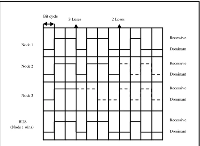
CAN was first developed for combining all electrical controls on a serial data bus in automotive applications (1, 2). Because of its low cost and high speed, CAN technology has also become popular for industrial environments (3, 4, 5, 6, 7). The CAN standard corresponds to Layers 1 (Physical Layer), and 2 (Data Link Layer) of the OSI (Open System Interconnection) reference model (8, 9, 10). A scheme, known as CSMA/CD with non-destructive bit-wise arbitration, is used for medium access control (8, 11). In this scheme, each node on the CAN bus has a unique identifier and this identifier is used for arbitration. While a station is competing for the bus, it also observes if its data is the same as the data on the bus. If different, the node assumes that a higher priority message is already on the bus and switches to receiving mode. In this way, the highest priority message is ensured to get the bus while lower priority messages are sent later. With this method, no time is wasted on collisions and valuable bandwidth is saved (12, 13).
Figure 1. Bit-wise arbitration between CAN nodes. However, this arbitration mechanism limits the bus length, because all stations have to observe each other within a period of one bit time. Because of the propagation delay on a bus and the delays of nodes, CAN segments have to be short, only 40m at 1 Mbps. In industrial applications, to extend the network size provides more efficient use of large scale distributed control systems. Two solutions can be introduced to increase the usable distance.
Time Quantum Oscillator
Baudrate Prescaler
Bit-Time
SYNC_SEG PROP_SEG PHASE_SEG1 PHASE_SEG2
Sample Point
Nominal Bit-time
Sync_Seg: 1 tq Prop_Seg + Phase_Seg1: 1-16 tq Phase_Seg2 : 1-8 tq
The first is to decrease the data rate, hence the time for one bit is increased. The second solution is to use additional interconnection devices, such as bridges. It has been an interesting research area and various studies were carried out to extend the bus length of CAN (14, 15, 16). This requires a good understanding of the CAN bit-timing and the delay sources of a CAN system. In this respect, this paper gives a detailed analysis of the reasons for the bus length limitation of these systems. 2. LIMITATION OF CAN BUS LENGTH
The maximum length of a CAN bus is determined essentially by the following physical effects (8, 17):
The loop delays of the connected bus nodes (CAN controller, transceiver) and the delay of the bus line.
The differences in bit Time Quantum length due to the relative oscillator tolerance between nodes.
The signal amplitude drop due to the series resistance of the bus cable and the input resistance of bus nodes.
The third requirement is related to the DC characteristics of the system. The first two factors are related to the protocol structure and bit timing features of CAN, and the following gives a technical overview of these factors.
3. CAN BIT-TIMING
An important feature of the CAN protocol is that the bit-rate and the bit sample point can be defined by the user. This provides the user with the freedom to optimize the performance of the network according to the requirements of different application. During the optimization process, the relationship between the bit timing parameters, the reference oscillator tolerance, and various signal propagation delays in the system must be taken into account. For example, choosing a later sample point in the bit period results in more tolerance for propagation delay, and greater bus length. On the other hand, choosing a sample point closer to the mid-point of the bit period will allow greater oscillator tolerance for each node in the system. These examples show that a larger allowable oscillator tolerance and a long bus length are conflicting goals (18, 19).
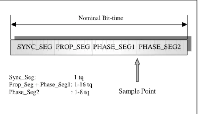
Figure 2. Time Quantum and Bit-timing. Bit-timing is the main issue in determining the bus distance in a CAN system. The basic unit in bit timing is called the Time Quantum, TQ. Each bit segment is comprised of an integer multiple of the TQ. The Time Quantum is the smallest discrete timing resolution used by a CAN node, and its length is generated by a programmable divide of the CAN node oscillator frequency. One bit contains a minimum of 8 and a maximum of 25 Time Quanta. The bit time is selected in the CAN controllers by programming the width of the Time Quantum and the number of Time Quanta in various segments of a bit. Figure 2 shows the derivation of Time Quantum from oscillator signal together with bit timing process.
As can be seen form Figure 3, a CAN bit period can be divided into four non-overlapping time segments that are comprised of a number of Time Quanta.
Figure 3. Segmentation of one CAN bit-time and Sample Point.
SYNC_SEG contains a fixed 1 Time Quantum field. It is used to synchronise the bus nodes. An edge is expected to lie within this segment.
PROP_SEG has a programmable length that can vary from 1 to 8 Time Quanta. This field is used to compensate for the signal propagation delays across the network.
•
•
Transmitting CAN Node Transceiver Receiving CAN Node Transceiver CAN BUS Node A Node B PROP_SEG
SYNC_SEG PHASE_SEG1 PHASE_SEG2
Node A
PROP_SEG
SYNC_SEG PHASE_SEG1 PHASE_SEG2
tprop(A,B)
tprop(B,A)
Node B
Sample point Bit from Node A
Bit from Node B
Sample point PHASE_SEG1 field-length can be
programmed between 1 and 8 Time Quanta long. It is used to compensate for edge phase errors and may be lengthened during resynchronization. PHASE_SEG1 together with PROP_SEG is also referred as TSEG1.
PHASE SEG2 includes the Information Processing Time and may contain 1 to 8 Time Quanta. This field is also used to compensate edge phase errors and may be shortened during resynchronization. Information Processing Time is less than or equal to 2 Time Quanta. It starts with the sample point and reserved for calculation of the bit level. The sample point is the point of time at which the bus level is read and interpreted as the value of the respective bit. It is allocated at the end of PHASE_SEG1. PHASE_SEG2 is also referred as TSEG2.
Bit timing can be optimized by programming the sample point. As mentioned earlier, a late sampling allows a maximum bus length, while an early sampling allows slower rising and falling edges.
4. PROPAGATION DELAY
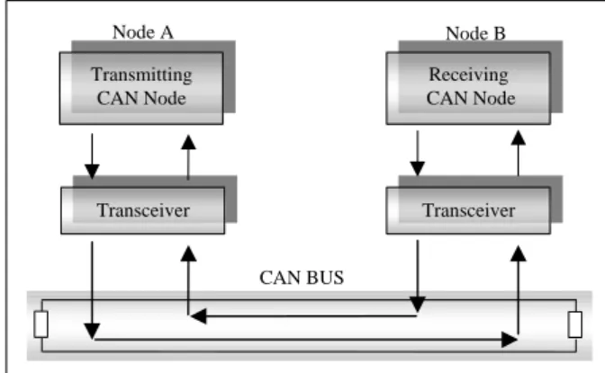
The significance of propagation delay in a CAN system is the result of the fact that CAN allows for non-destructive bit-wise arbitration between nodes contending for access to the network, as well as in-frame acknowledgement (18, 20). During the arbitration, multiple nodes simultaneously drive their identifier bits onto the bus. As nodes synchronize on bit edges, excessive propagation delay in the system results in invalid arbitration. There are various delays in a CAN system that limits the maximum bus length.
Figure 4. Signal propagation delay in a CAN system.
Figure 4 illustrates the signal path and the propagation delay factors between two CAN nodes. The one way propagation delay between two nodes, for example node A and node B, can be defined as tprop(A,B). The total delay is the sum of
the delays of devices in the signal path, including the transceiver (120 ns to 250 ns), the CAN controller (50 ns to 62 ns), and the bus cable (about 5 ns/m). Nodes must receive each other’s signals, synchronise to them, and then transmit back during arbitration. This is because after synchronization, the most far end node expects switching edges with delay of propagation time, and the bit of the transmitter has to wait another propagation time to guarantee that the identifier bit or the Acknowledge slot bit of the receiver is valid. Therefore the total propagation delay in the system is the sum of the two node’s delays. The total round-trip (or loop) delay, defined as tpropagation, can be expressed as:
tpropagation = 2 ( tcable + tcontroller + ttransceiver )
Equation 1. (18)
Figure 5. Effect of propagation delay between nodes.
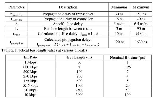
The effect of the propagation delay on signal transmission between two nodes can be seen from Figure 5. Table 1 shows an example of propagation delay in a CAN system. In this example the maximum delay, which is 1630 ns, takes approximately 41% of a CAN bit-time at 250 kbps bus speed. Therefore, it is necessary to compensate for signal propagation delays, and the total propagation delay has to be less than the length of the Propagation Time Segment (PROP_SEG) within one bit. This can be considered as the main reason that a CAN bus has to be at a limited length at a given bit-rate. More detailed explanations and application examples related to calculation of CAN bit-timing
1
t
SYNC_SEG SJW1 Restarted SJW1 SJW2 Sample Point Input Signal Actual Bit-time Nominal Bit-time TSeg1 TSeg2
parameters and limitation of CAN bus length can be found in references (8, 18, 19). In Table 2 practical bus length and bit-time values for different bus speeds are given.
5. SYNCHRONIZATION
Bit synchronization is an important issue in bit timing, and therefore it also affects the CAN bus length. Synchronization guarantees that messages are properly decoded despite phase errors, which may accumulate between nodes (8, 11, 18, 19, 21). The main reasons for phase errors are oscillator drift, propagation delays between nodes spatially distributed on the network, or phase errors caused by noise disturbances. There are two types of synchronization defined as hard synchronization and resynchronization, also known as soft synchronization.
Hard synchronization is only performed at the beginning of a message frame. After an idle period, every CAN controller on the network initializes its current bit period timing at the first received recessive to dominant edge with SYNC_SEG. Resynchronization is subsequently performed once at each received recessive to dominant edge throughout the remainder of the message.
During resynchronization, if an edge is received after SYNC_SEG and before the sample point of the receiver, the receiver interprets it as a late edge from a slower transmitter. In this case,
the PHASE_SEG1 segment of the receiver is lengthened to match the timing of the transmitter with better accuracy. Figure 6 shows the resynchronization of a receiver to a slow transmitter.
Figure 6. Resynchronization to a slower transmitter.
Conversely, if the receiver detects an edge after its sample point and before the SYNC_SEG, Table 1. An example of propagation delay in a CAN system.
Parameter Description Minimum Maximum
ttransceiver Propagation delay of transceiver 30 ns 157 ns
tcontroller Propagation delay of controller 15 ns 40 ns
Specific line delay 5 ns/m 6.5 ns/m
L Bus line length between nodes 3 m 95 m
tcable Calculated bus line delay: tcable = L . 15 ns 618 ns
tpropagation
Calculated propagation delay: tpropagation = 2 ( tcable + tcontroller + ttransceiver )
120 ns 1630 ns Table 2. Practical bus length values at various bit-rates.
Bit Rate Bus Length (m) Nominal Bit-time ( s)
1 Mbps 30 1 800 kbps 50 1.25 500 kbps 100 2 250 kbps 250 4 125 kbps 500 8 62.5 kbps 1000 20 20 kbps 2500 50 10 kbps 5000 100 8
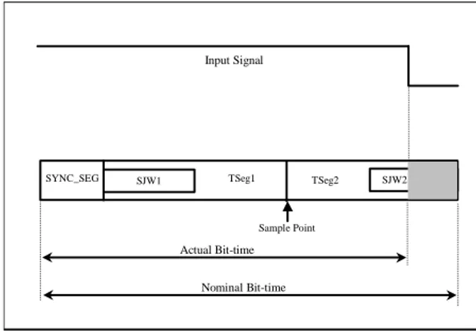
SYNC_SEG SJW1 SJW2 Sample Point Input Signal Nominal Bit-time Actual Bit-time TSeg1 TSeg2
that is, during the PHASE_SEG2 segment, this is interpreted as an early edge and the next bit period is sent by a faster node. In such a case, the receiver shortens its PHASE_SEG2 period to match the timing of the faster transmitter. The maximum number of TQ by which a bit period may be lengthened or shortened during resynchronization is specified by the programmable Synchronous Jump Width (SJW). The SJW1 and SJW2 fields have the same length, and are equal to the given SJW value in a bit period. In Figure 7, the resynchronization of a receiver to a fast transmitter is illustrated.
Figure 7. Resynchronization to a faster transmitter. All the segments within a CAN bit period consist of an integer number of TQ. Therefore, resynchronization only occurs if the absolute phase error is greater than one TQ. Even between two nodes of the network with the same oscillator reference frequency, there may be an uncertainty of one TQ in synchronization.
6. DISCUSSION AND CONCLUSION
The subjects mentioned above are of great interest from the point of the research studies on CAN. These subjects must be taken into account in order to use a CAN system under optimum conditions. Moreover, in research studies on the extension of the CAN system size these are the main considerations that form a basis for researchers. There have been various studies to extend the usable distance of CAN. These include the extension methods between CAN to CAN systems as well as the methods involving different network types interconnecting CAN systems (14, 15, 16, 22, 23).
In this paper, a detailed analysis of the CAN bit-timing and the delays on a CAN bus has been given. Since its first introduction in automotive industry, CAN has gained a great interest in various industrial areas. This brought together the need to use it on larger scales in distributed control environments. Therefore, it has been an interesting area for researchers to extend the usable distance of a CAN system. This requires a good understanding of the CAN protocol structure and the reasons for delays in a CAN system. In this respect, this paper provided a brief overview of the medium access method of the CAN protocol together with a detailed analysis of parameters and components that bring about a CAN bit. The effects of these parameters and the synchronization process were explained. Practical bus length values at various bit rates together with the delay analysis of a CAN system were also illustrated. REFERENCES:
1. State of the Art and Future Applications - CAN in Automobiles, CAN Newsletter, pages 52, 54, 56, 58, March 1999.
2. Khoh, S.B., Mclaughlin, R.T., Autos carry the CAN, Assembly Automation, vol. 14, no 1, MCB University Press, 1994
3. Fredriksson, L. B., Controller Area networks and The Protocol CAN For Machine Control Systems, Mechatronics, vol. 4, no.2, pp. 159-172, 1994.
4. Mueller, M., Rembold, D., and Woern, H., Communication Architecture for a Robot Cell, CAN Newsletter, pp. 62-63, September 1999. 5. NMEA 2000: CAN in Marine Electronics,
CAN Newsletter, pp. 52-53, June 1999.
6. Hi-tex, Controller Area Network - The Future of Industrial Microprocessor Communications, Hitex UK Ltd. C51/166 Newsletter, January 1995.
<www.hitex.demon.co.uk/CAN/canarticle.html >
7. Korane, K. J., Mobile Machines Get CAN in Gear, Machine Design, pp. 50-53, September 1996.
8. Lawrenz, W., CAN System Engineering From Theory to Practical Applications, Springer-Verlag Inc., New York, 1997.
~
1 1
1
•
.
t
9. Halsall, F., Data Communications, Computer Networks and Open Systems, Fourth Edition, Addison-Wesley Publishing Company Inc, USA, 1996.
10. CAN Physical Layer for Industrial Applications, CiA Draft Standard Proposal DSP 102, Version 2.0, 1994.
11. Bosch, CAN Specification, Version 2.0, Robert Bosch GmbH, Germany, 1991.
12. Tindell, K., Burns, A., Guaranteeing Message Latencies on Controller Area Network (CAN), Proc. 1st International CAN Conference, Germany, Sept. 1994.
13. Tindell, K., An Extendible Approach for Analysing Fixed Priority Hard Real-time Tasks, Real-Time Systems, 6 (2), pp. 133-151, 1994. 14. Thomas, G. M., Real-Time Performance of
Bridged CAN Networks, CAN Newsletter, pp. 50-52, September 1998.
15. Tenruh, M., Stipidis, E., and English, M. J., Design and Software Implementation of a CAN/CAN Cut-through Bridge, Proceedings ICC’99 6th
International CAN Conference, Italy, 1999.
16. Tenruh, M., Stipidis, E, English, M. J., Performance Analysis of Cut-through Bridged CAN Systems, INC’2000 2nd
International Network Conference, Plymouth UK, pp. 75-82, July 2000.
17. Eisele, H., Johnk, E., PCA 82C250/251 CAN Transceiver, Application Note AN96116,
Philips Product Concept & Application Laboratory, Germany, 1996.
18. Johnk, E., Dietmayer, K., Determination of Bit Timing Parameters for SJA 1000 CAN Controller, Application Note AN97046, Philips Systems Laboratory, Germany, 1997.
19. Hartwich, F., Bassemir, A., The Configuration of the CAN Bit Timing, 6th International CAN Conference, Italy, 1999.
20. CAN Physical Layer, CiA CAN Presentations, <www.can-cia.de>
21. Hank, P., Johnk, E., SJA 1000 Stand-alone CAN Controller, Application Note AN97076, Philips Systems Laboratory, Germany, 1997. 22. Tenruh, M., Stipidis, E., English, M. J.,
Extending Controller Area Networks over ATM, ISCIS’2000, 14th
International Symposium on Computer and Information Sciences, October 2000.
23. Tenruh, M., Stipidis, E., English, M. J., Performance Analysis of CAN/ATM Bridging, CAN Newsletter, pp. 24-25, Issue 3, September, 2000.