PLANE-WAVS DYNAMICS OF SINGLE GEYSTAL
UPGONVEESION OPTICAL PAHAMSTiUG
OSGiLLATOES
A T S M m B
SUBM ITTED TO TH E DEPAHTLgBNT
BL1CTE2CAL AND
B L B G T B O IH C S E M O IH S H E IH G
AND TMM IN B T U T E OF m Q G lN S E m m G AMD SCIINCBB
O F B iL E S M T u m w m B i T iIN PARTIAL FULFiLLM EHT OF TME RZQU2RSMBKTS
FO E THE D EG ESS OF
MASTER OF S.CISNG1
PLANE-WAVE DYNAMICS OF SINGLE CRYSTAL
UPCONVERSION OPTICAL PARAMETRIC
OSCILLATORS
A THESIS
SUBMITTED TO THE DEPARTMENT OF ELECTRICAL AND ELECTRONICS ENGINEERING
AND THE INSTITUTE OF ENGINEERING AND SCIENCES OF BILKENT UNIVERSITY
IN PARTIAL FULFILLMENT OF THE REQUIREMENTS FOR THE DEGREE OF
MASTER OF SCIENCE
By
Giilbin Akgiin
January 1999
Ί Κ
I (’.(irtify that I have read this thesis and that in iriy opinion it is hdly adeipiate, in scop(', and in quality, as a thesis for the degr(ie of Mastcu· of Scitnieii.
Assoc. Prof. Dr. Orhan Aytür (Supervisor)
I cxiitify that I have read this thesis and that in iny opinion it is fully adequate, in scope and in quality, as a thesis for the degree of Master of Sciencxi.
I (xu tily that I have read this thesis and that in niy oi)inion it is fully axhxiuatxi, in scxjpe and in quality, as a thesis for the/legnx! of MastiU' ol Sciinux'.
ssoc. Pr6f. Dr. (ynıer Morgül
Approved for the Institute of EngiiKxuing and ScieiKX's:
Prof. Dr. Mehincit Ba,ray
Director of Institute of Engineering andi>ll:i(;mx!s
ABSTRACT
PLANE-WAVE DYNAMICS OF SINGLE CRYSTAL
UPCONVERSION OPTICAL PARAMETRIC
OSCILLATORS
Giilbin Akgun
M.S. in Electrical and Electronics Engineering
Supervisor: Assoc. Prof. Dr. Orlian Aytiir
January 1999
Tliis diesis presents our investigation of the dynamics of single crystal up- conversion optical parametric oscillators (OPO’s). In tlnise devices, parametric generation and sum frequency generation or second harmonic geruuation pro cesses are simultaneously phase matched in a single crystal for the sariKi direction of projiagation. These devices can be categorized diipending on the polarization geometries of the interacting fields leading to simultaneous phase matching of the two processes. The dynamics of these OPO’s are analyzinl using a discrete dynamical system representation. The dependence of the dynamics of the system on various parameters is investigated by forming bifurc:ation diagrams. R.egions of stable steady state, multistable, periodic and chaotic opc'.ration an; id(;ntihed on these diagrams.
Keywords: optical parametric oscillation, sum-fn;qu(;ncy geii(;ra.tiou, s(;cond harmonic generation, simultaneous phase-matching, discr(;t(; dynamical syst(;ms, chaos.
ÖZET
TEK KRİSTALLİ YUKARI-DÖNÜŞÜM OPTİK PARAMETRİK
OSİLATÖRLERİNİN DÜZLEM-DALGA DİNAMİĞİ
Gülbin Akgün
Elektrik ve Elektronik Mühendisliği Yüksek Lisans
Tez Yöneticisi; Doç. Dr. Orhan Aytür
Ocak 1999
Bu tezde, tek kristalli yukarı dönücüm optik parametrik osilatorhu-inin (OPO) dinamiğinin incelenmesi sunulmaktadır. Bu cihazlarda, parametrik üretim ve toplam frekans üretimi ya da ikinci tiarmonik üriitimi sürekleri tovk kristal ilginde aynı yayılım yönü için birlikte faz ei^lidir. Etkile.'^en alanların iki sürecin aynı anda faz eşli olmasını sağlayan polarizasyon geoni(;trilerine bağlı olarak luı ci hazlar çeşitli sınıflara ayrılabilir. Bu OPO’lamı dinamiği ayrık dinamik sistem gösterimi kullanılarak çözümlenmiştir. Sistemin dinamiğiniıı bir çok ııaramet- reye olan bağlılığı çatallanma diyagramları kullanılarak araştırılmıştır. Bu di yagramlarda kararlı sürekli hal, çok kararlı, periyodik ve kaotik çalışma, bölgelini belirlenmiştir.
Anahtar Kelimeler: optik parametrik salımın, toplam-frekans üretimi, ikinci Inumonik üretimi, aynı anda faz eşleme, ayrık dinamik sistemhn·, kaos.
ACKN O WLEDGMENTS
I gratefully thank rriy supervisor Dr. Orhan Aytür for his suggristioiis, super vision and guidance throughout the development of this tlnîsis.
I would also like to thank Dr. Ir^adi Aksun and Dr. Onier Morgiil, the members of my jury, for reading and commenting on the thesis.
Many thanks to Yamaç Dikmelik, Lütfiye Durak, Tolga Kartaloğlu and Güçlü Köprülü not only for making it fun to work together bnt also for tlnür friendship, and to Deniz Gürkan, Arçm Bozkurt, Tolga Ekmekçi, Ayhan Bozkurt, Serdal Ç(!vik and Hatice Afacan for their friendship and support.
Finally, I would like to thank my family for the love and (uic.ouragcunent they gave me throughout my life.
C ontents
1 IN T R O D U C T IO N 1
2 D ISC R E T E D Y N A M IC A L SY STEM S 4
2.1 Discrete Dynamical S y s te m s... 4
2.2 Fixed and Periodic Points 4 2.3 Graphical .\ n a ly s is ... 5
2.4 Parametrized Families of Functions and B ifu rca tio n ... 7
2.5 Chaos and Period Doubling 7 3 SE C O N D O R D E R N O N L IN E A R O PTICAL IN T E R A C T IO N S 10 3.1 The Driven Wave Equation 10 3.2 Coupled Mode E quations... 12
3.3 Optical Parametric A m p lificatio n ... 14
3.4 Sum Frequency G eneration... 15
3.5 Second Harmonic Generation 16 3.6 Phase M atch in g ... 17
3.6.1 Biréfringent Phase M atching... 18
3.6.2 Quasi-Phase M a tc h in g ... 19
3.7 Optical Parametric Fluorescence... 20
4 U P C O N V E R S IO N OPTICAL PA R A M E T R IC OSCILLATORS 22 4.1 Intracavity Fi-equency Upconversion... 22
4.1.1 Optical Parametric Oscillation with Intracavity Sum Fre-(piency G e n e ra tio n ... 22
4.1.2 Optical Parametric Oscillation with Intracavity Second Har monic G en eratio n ... 24
4.2 Single-Grystal Frequency Upconversion OPO’s ... 25
4.2.1 Single Crystal Sum Frequency Gemnating Optical Para metric O scillators... 25
4.2.2 Self-Doubling Optical Parametric O scillators... 31
5 D Y N A M IC S OF U P C O N V E R SIO N O PO ’s 35
5.1 Upcoiiversion OPO as a Discrete Dynamical Systcun... 35
5.2 Dynamics of SF-OPO’s ... 38
5.2.1 Dynamics of Class-A SF-OPO’s ... 38
5.2.2 Dynamics of Class-B SF-OPO’s ... 41
5.2.3 Dynamics of Class-C SF-OPO’s ... 4G 5.2.4 Dynamics of Class-D SF-OPO’s ... 52
5.3 Dynamics of SD-OPO’s ... 54
5.3.1 Dynamics of Class-A SD-OPO’s ... 54
5.3.2 Dynamics of Class-B SD-OPO’s ... 55
5.3.3 Dynamics of Class-C SD-OPO’s ... 55
List of Figures
2.1 Illustration of graphical analysis. Tlu; iixcid ])oint c is shown with a filled circle... 5 2.2 A period 2 cycle identified by graphical analysis... 6
2.3 Second iterate of the function in Figure 2.2. 6
2.4 Bifurcation diagram... 8 2.5 Demonstration of period doubling with plots of l\ and f j for thi(;(i
parameter values... 9 3.1 Phase matching types for three held interac:tious. Tin; horizontal
and vertical directions correspond to the fast and slow a.x(!s of the crystal... 3.2 Phase matching types for SHG. The horizontal and vertical dir(H·,-
tions correspond to the fast and slow axes of the crystal.
4.1 OPO with intracavity SFG where the SF'G cr^^stal i)recedes the OPO crystal... 4.2 OPO with intracavity SFG where tin; OPO crystal i)reced(is the
SFG crystal... 4.3 OPO with intracavity SHG... 4.4 Cavity conhguration of SF-OPO... 4.5 Potential phase matching geometries for the SF-OPO... 4.0 Self-doubling OPO cavity conhguration... 4.7 Potential phase matching geometries for the SD-OIT).
5.1 Conversion efficiency versus nonlinear driven for (4ass-A SF-OPO, for various loss values... 5.2 Conversion efficiency versus nonlinear driv(! for (4ass-A SF-OPO,
for various β values... 40 5.3 Single and multiple steady states identihed l)y grai)hical analysis. 41 5.4 Conversion efficiency with respect to ratio of parametric fluores
cence to pump photon flux. 42
18 19 23 23 24 25 26 31 32 39 Vlll
5.5 Contour plots of conversion efficiency with respect to nonlimiar drive and pump polarization rotation in class-B SF-OPO’s for four different p values... 4-3 5.6 Conversion efficiency (r/), pump depletion (pd) and rota,t(!(l pump
depletion (rpd) with respect to for cla.ss-B SF-OPO’s for various ft values... 44 5.7 Gain curves for < au,. and a,, > «/,/,... 46 5.8 Conversion efficiency with respect to nonlinear drive in cla.ss-B
SF-OPO ’s for various ft values and a^, optimized ni D = 1... 47 5.9 Conversion efficiency with respect to a,, in cla,ss-B SF-OPO’s for
various ft values and D = 10... 48 5.10 Conversion efficiency with respect to nonlinear driv('. in class-B
SF-O PSF-O ’s for various ft values and cvp optimized at D = 10... 49 5.11 Contour plots of conversion efficiency with i(!S])(!ct to nonlimiar
drive and pump polarization rotation in class-C SF-OPO’s for four different ft values... 50 5.12 Conversion efficiency (r/), pump depletion (i)d) and rotated i)ump
depletion (rpd) with respect to a.p for class-C SF-OPO’s for various ft values... 51 5.13 Conversion efficiency with respect to nonlino',a.r driven in class-C
SF-OPO ’s for various ft values and (Xp optimized at D = 1... 57 5.14 A period 2 cj'^cle identified by graphical analysis... 58 5.15 Conversion efficiency with respect to o;,, in class-C SF-OPO’s for
various ft values and Z) = 10... 59 5.16 Conversion efficiency with respect to nonliiKiar drivci in class-C
SF-O PSF-O ’s for various ft values and optimized at D = 10... 60 5.17 Contour plots of conversion efficiency with respect to nonlinear
drive and signal polarization rotation in class-D SF-OPO’s for four different ft values... 61 5.18 Conversion efficiency with respect to nonlimiar drive! in class-D
SF-OPO’s for various ft values and a,, optimized at D = 1... 62 5.19 Conversion efficiency with respect to in class-D SF-OPO’s for
various ft values and D = 10... 6-3 5.20 Conversion efficiency with respect to nonlinear drive! in e:lass-D
SF-OPO’s for various ft values and cv.^ optimize!el a.t D = 10. . . . 64 5.21 Conversion efficiency with respect te> ne)iilin(!ar drive! in e:lass-A
SD-OPO’s for various ft values... 65 5.22 Conversion efficiency with respect to ft in e;la,ss-A SD-OPO’s
5.23 Conversion efficiency with respect to nonlimvir drivi', in class-C SD-OPO’s for varions ft values and cv,, optimized a.t D = \ ... G7 5.24 Conversion efficiency with respect to a.^ in class-C SD-OPO’s for
various [3 values and D = \()... G8 5.25 Conversion efficiency with respect to nonlinear driv(; in cla,ss-CJ
List of Tables
4.1 Potential phase matching geometries for the SF-OPO. 4.2 Potential phase matching geometries for th(i SD-OPO.
26 32
Chapter 1
IN T R O D U C T IO N
Lasors are sources of radiation with high intensity, narrow bandwidth and small beam divergence. A particular application may require a radiation source with such proi^erties at a specific wavelength. However, most lasers oi)erate at discrete wavidengths, determined by energy level differenc(',s of tlui lasing matcu'ials. There a,re tunable lasers such as dye lasers, but their tunability is limited and they cover a small portion of the spectrum.
Nonlinear optics offers a solution to this problem. Within nonliiKuir optical materials, the frequency of an incoming laser radiation can l)c tunably converted to another frequency. This is due to the nonlinear dependimce of the j^olariza- tion density on the electric field in such materials. The second order noidinear l)olarization at each possible frequency acts as a source for gemnation of (dcictric fiidd a.t that frequency.
Τίκΐ second order nonlinear interactions result in second harmonic genera- i.ion (SHG), sum frequency generation (SFG) or diihu'iuice fre(iuency gruieration (DFG). In SHG, the frequency of the input las(!r beam is convert(!d to its second harmonic. For SFG, two radiation sources are reciuired, a.nd radiation a.t the sum of the two frequencies is generated. Two radiation sourc(;s an^ also nec(!ssary for DFG, where the difference of the two frequencies is gcuierated.
Another second order nonlinear optical proce.ss is o[)tical parametric amplifi cation where the field with the smaller frequency of tin; DFG process is amplified. An optical parametric oscillator (OPO) can be formed by placing this ampliher in an optical cavity. A single laser, called the OPO puiiq), is rc(iuir(Hl to start the OPO oi)eration. In this case, the lower frequency ini)ut field for this intcuaction is provided by optical parametric fluorescence. Tlu; OPO output is tunal)le dru! to this fact. The wavelength of the output can be tuned by manii)ulating the moiiKuiturn conservation (phase matching) condition l)y rotating tin; crystal or changing the crystal temperature.
ί(, is not possible to obtain a tunable frequency higher than that of the input pump held with a single nonlinear optical process. Cascading eitlnn· SFG or SHG with the OPA process has been used to achieve this goal. Phicing a s(!cond iionliuear crystal within the OPO cavity is preferred to otlnu· conligurations in order to take advantage of the high intracavity signal held intensity. Tin; second nonliiKiar crystal is either for SHG [1], [2] or for SFG [3], [4]. The; th(!ory of these devices under the plane-wave approximation was invivstigated l)y different r(!searchers [5], [6], [7].
There have been recent reports of single crystal upconveusion ()PO ’s where SHG [8] or SFG [9] and the parametric generation process a.i(! phase-matched in a single crystal for the same direction of propagation. Simultaneous phase matching of two or three interactions in a single crystal were a,Iso r(!ported in the early period of nonlinear optics studies [10], [11]. Tin; recent (hivelopment of (luasi-phase-rnatching (QPM) methods allowed for the use of this technique in single crystal upconversion OPO’s. Such experiments inchuhi O PO ’s with simultaneous SHG [12], [13] and SFG [14], [15].
Nonlinear optical systems are also important in tin; study of dynamics, be- ca,us(! of their nonlinear nature. If sufficiently high pumping levods can be reached, they display multistable or periodic or chaotic Indiaviour.
Studies of nonlinear systems gained impetus with th(i (hivelopimuit of comi)ut- (',rs. It l)ecarne possible to perform the huge amount of coniputa,tions involved. Such studies were started by Lorentz who built a simple mod(4 of tlu! atmosphere including three nonlinear ordinary differential eciuations and used a computer to solve these equations [16]. The solutions were nonperiodic e\^(ui though they were governed by completely deterministic rules.
Discrete dynamical systems are used to model such proc(\ss(!s as population growth where the evolution of the system is obscuved at discrete intcuvals. The steady-state and periodic behaviour of these systems is well understood, but a complete understanding of chaotic behaviour is missing.
A discrete dynamical system approach has been applied to nonlinear optical systems before. These were used to model OPO’s with intrac.avity SFG [6] and SHG [7]. The dynamics of tandem OPO’s where the fre(iuency of the primary signal held is downconvertoid in a secondary OPO inocess (uther in a second crystal [17] or in the same crystal [18] have also Ikhui ;maiyzed by Ηκϊ sanu' t(!chniqu(!.
In this thesis, we present the dynamics of single crystal upconveusion O PO ’s. The tools of discrete dynamical system theory uschI in this analysis a,i(! outlined in Ghai)ter 2. Chapter 3 gives an overview of tlui second orchu· nonlin(!a,r optical
phaso! matching geometries and the coupled mode ecjuations for each class are provided in Chapter 4. In Chapter 5, we investigate! how tlu! dynamics of up- conv(!rsion O PO ’s depend on various parameters. Chapter G contains conclusions a.nd directions for further research.
Chapter 2
D ISC R ET E D Y N A M IC A L
SYSTEM S
111 this chapter, we summarize fimciarneiital concepts of discrete d^mamica,! sys tems theory. We present the defiiiitioiis of fixed and [leriodic [loiiits and describe ji,ra,i)hical analysis methods. We end the chapter with a. section on cha.os.
2.1
D iscrete D ynam ical S ystem s
Discrete dynamical systems can be mathematically represented by a. function that is composed with itself repeatedly [19]. The study of discrete dynamical systems is concerned with the convergence behaviour of the iteration of points under this function. The iterate of the function /(;/;) is
/ “(■■a = / ( / . . - ( .a ...) (2.1)
n lim e s
where the superscript n denotes the composition of / with itself n times [19]. The orbit of a point .x'o is defined as the seciuence of points [20]
•Xo, •i'-i = ./'(-A)), X2 = (2.2)
2.2
F ixed and Periodic P oints
The ])oints for which /(c) = c, called the fixed poinL· of / , are of })a.rticular importance, since all the iterates of c are eciual to itself. For a differentia.ble function / , if c is a fixed point and [/' (^01 < 1, then there is a neighbourhood of
point c is then called a stable fixed point [19]. If |/'(c)| > 1, c is an unstable fixed point, and there is a neighbourhood of c such that i)oints in this neighbourhood diverge from c with repeated applications of / .
A point Pi for which /^(p,;) = p,;, is a periodic point of / with i)criod k. The least such k is called the prime period of p,;. Periodic infints of / with ])criod k are fixed points of the function /*' and form a periodic orbit (cych;) such that
Pfc-i = f i Pk-2) = ... = Hpo)- (2.3) Th(! stability of this cycle is determined by the derivative of at a.ny ])oint of the cycle. By the chain rule, this derivative is same for (iach point of the cycle and is given by [20]
ify iiP i) = f'{Po)f'{Pi) · ■ · f { P k - i ) 'i- = 0,1,..., A: - 1. (2.4)
If the absolute value of this derivative is less than unity, the cychi is stal)le.
2.3
Graphical A nalysis
Graphical analysis is a visual aid in understanding the; dynamics of tlui function / . The graph of the function y = f{x) is plottoxl together with the y = x line. The intersection points of the two curves are the fixed points of /(;/;). The derivatives at these points determine their stability.
Figure 2.1: Illustration of graphical analysis. The fixed point c is shown with a filled circle.
Starting from an initial point ;ro, first a vertical line is drawn to the point (;;;(),/(.X’o))· The horizontal line drawn from this point to the y = x line touches
this line at (.'Ci,xi) = {f{xo),f{xo))· This process is repc'.ated at each iteration step [20]. Figure 2.1 illustrates this procedure. The value of the derivative at the fixed point c is zero, hence, it is a stable fix(id point and the itérât,ions conv(!rge towards it.
Figure 2.2: A period 2 cycle identified l)y gra|)hicai analysis.
Figure 2.3: Second iterate of the function in Figure 2.2.
In Figure 2.2, a periodic cycle is identified by graphical analysis. The iterations start with the initial point Xq and converge to a periodic cycle with prime jieriod 2. The cycle is composed of the points po and pi that are rcdated f)y pi = /(po) and Po = /(p i). Figure 2.3 shows the graph of the second iterate of tlui function in Figure 2.2. The absolute values of the derivatives of at the fixed points po
and Pi are both less than unity. Therefore, po and pi are stabh; hx(!(l i)oints of the function P{x) . The point c, shown with an eini)ty circh', in Figures 2.2 and 2.3, is all unstable fixed point of both / and p .
2.4
Param etrized Families o f Functions and B i
furcation
A parametrized family of functions is a collection of functions f\{x) of the same general type and having a parameter A in their definition [19]. As this parameter changes, the dynamics of the function may change. For example, as tlui parameter is slightly changed a stable fixed point may become unstable and iieriodic points may appear. This kind of a change of behaviour is calhid a bifurcation. This signili(!s a splitting of the dynamics into two different tyiuis of liehaviour below and aJiove the bifurcation value of the parameter.
A liifurcation diagram is a compact nipresentation of tlu' (hipendence of the dynamical behaviour of a family of functions on the jiaranuiter A. In this diagram, th(! horizontal axis contains the parameter values, whenxis tlui values of the fixed or jicriodic points are plotted on a vertical line for each pai'ameter [21]. To form a. bifurcation diagram, an initial point xq is chosen and the itcuations sta,rt. After th(! transients die away, several values of subse(]uent .i;„’s a.i(i plotted along a, vca tical line that passes through the corresponding i)a.ranieter vahuc if tluu’e is a, stable, fixed point of the function for that i)ara.ni(!t(!r value, tluui all values art! etiual to that fixed point. If the orbit settles into a ptii iodic cyclt! with ptiriod k, then there are k points along the vertical line at that p;uameter value.. An (!xample bifurcation diagram is shown in Figure 2.4. The function f\{x) ha.s a stable hxed point for the parameter values A] < A < A^. At A = A^, a bifurcation occurs and for A2 < A < A4, there are two periodic points. At A = A/| another period doubling occurs and there are four points with pciiiod 4 for th(! parameter values between A4 and Ag.
2.5
Chaos and Period D oubling
Chaos has several definitions. The definition l>y Devaiuiy (!ni])ha.siz(!s s(!iisitivity to initial conditions [21]. Sensitive dependence on initial conditions iiuians that two i)oints arbitrarily close to each other get se])arated und(!r it(!ration of / . If tli(! syst(!in is chaotic, two initial states that arc' very close! to (!a,di oth(!r have (!xponentially diverging trajectories. Since, in ])ractic(!, it is impossible! to s(!t
Figure 2.4: Bifurcation diagram.
the initial state of a system with infinite precision, its future beliaviour will be unpredictable, although the system is completely deterministic.
For some values of the parameter the behaviour of the system may be simple. As the parameter changes, the behaviour may change from simple to complex, or from orderly to chaotic. In nonlinear systems, there a.re different ways of transition from simple to complex behaviour. These transitions are called routes to chaos. The most common transition to chaos is the period doubling route to chaos. As the parameter changes, a stable fixed point of f\{x) becomes unstable and two points with period two are created. These two points are stable fixed [)oints of the function fx{x)· As the parameter changes further, each fixed point of the function fx{x) splits into two new points. These period doublings go on until the period becomes infinite.
Figure 2.5 shows plots of functions fx{x) and f 'x{x) for three values of the parameter A. In parts (a) and (b), the parameter A is less than the bifurcation value A2. Both fx{x) and fx(x) have single stal)le fixed points. The absolute values of the derivatives at these points are less than unity. Parts (c) and (d) are drawn for the bifurcation value A2 of the parameter. The derivatives at the fixed points have unit absolute value. In parts (e) and (f), the parameter slightly exceeds the bifurcation value. There are two new fixed points {p^) and p\) of fx(x)
(c:) /a (·'<;) with A = A2. (d) fli'x) with A = A·).
Figuro 2.5: parainoter values.
Chapter 3
SECO N D O RDER N O N L IN E A R
O PTICAL IN TE R A C TIO N S
la I his cliai)ter, we presiuit the driven wave ecination tlmt dciserilHis tlui pr()|)aga- tion of light in a nonlinear medinin in which thoi polarization (k'.nsity is a. nonlinear rnnction of the electric held. We next present the coupled modi! (Hjiiations for difference frequency generation (DFG), sum frecnuuicy g(in(ira,tion (SFG) and sec ond harmonic generation (SHG) processes. These nonlimiar optical intiu'actions r(!sult from the second order dependence of the pohuization acting as a source for radiation at frequencies other than that of th(! incidemt Held. W(i lUixt discuss the phase matching condition that is required for (dficiiait freciiuiiicy conviusion. \'Ve conclude this chapter with a discussion of optical parametric liuoresccmce.
3.1
T he D riven W ave Equation
iVlaxwcdl’s eciuations
(3.1) (3.2) (3.3) (3.4) in a medium with no free charges or currents (p = (), J = 0) gov('rn tin' tiimi and
spac(! (ivolution of electromagnetic radiation, wlnue D and B arci the (dectric and magiKitic flux densities, and E and H are the electric and magiKdlc Ihdds. If the nKidium is nonmagnetic, the constitutive relations arci
V D - 0 V B = 0 V X E OB ~ ~~0t V X H OD I n D = coE + P (3.5)
в
= /v-оН (3.6) where /¿o and eo are the permeability and [iermittivity of fr(>.e .spa,ee a.nd P is the polarization induced in the medium [22]. TIk; polarization is induccid by theincidiiiit electric field and for nonlinear materials it is (ixprcissiid as a. pow(ir s(ui(!s
60 ■ E + E · · E + E · (E · x'·’) ■ E) + h.o.t. = + P(^) + P(®) + h.o.t.
(3.7) (3.8) Here, x^6 if. linear susceptibility tensor, and x^·^^ and x^b a.ni the second and third order nonlinear susceptibility tensors, respectivcdy. P^^^ is the liiKiar i)art of the polarization whereas P6h (n > 1) is called tlu! n'''- ord(U' polarization. In this thesis, we investigate second order nonlinear (dfects in optical systems and neglect any higher order effects.
Taking the curl of Equation (3.3), interchanging the order of tiiiK! and space derivatives and inserting Equations (3.4) and (3.6), we g(4,
(3.9) V X V X E = -//,()
dt:^ The vector identity
V x V x E = V ( V - E ) - V'-^E (3.10) ca.n b(i inserted into Equation (3.9). Maxwell’s equation (3.1) implicis V -E = 0 for a, homogeneous medium. However, this does not hold for nonlimiar тснИа. diui to tlui geiKual relation (3.5) between D and E. If tlu; inter;u:ting licilds a.i(! assumed to be transverse, infinite plane waves, the left hand sidci of E(iuation (3.9) can b(i replaced by — V^E, because the divergence of E is identically ziuo for a plane wave [22]. Then, Equation (3.9) becomes
(3.11) The electric flux density vector can be separatixl into two [)arts that depend liiKxirly and nonlinearly on E as
wluire
D = + P(^)
= 6oE + p(^).
(3.12)
(3.13) For a given direction of propagation, an anisotropic medium has two line.ar (ugen- I)olarization states. If the incident radiation held has omi of tluise two polarization stiites, then tin; linear susceptibility can be r(!pr(!S(iiited I>y a. scalar ratluu· than a t('nsor, luiiice
= eo(l+X^'^)E. (3.14)
Th(i driven wave equation is then obtained as V^E TV d'^E
cl dt^
=
//'()-¿)2p{2)(3.15) where oq = 1 /y'/xoeo is the speed of light in vacnnni, n = + x(' ) is tlui ndi active index (ixperienced by the held and the nonlinear [)olari/,ation acts as a flriving te.rni [22].
3.2
C oupled M ode Equations
Consideration of the polarization densities at si)ecific fr(i(iu(inci(!s in the driven wa,ve eciiiation leads to a description of siiveral nonlinear oi)tical interactions [22]. in th(!se interactions, three helds whose angular frecpiendiis a,re; redated by uj:i — to\ + 0J2 are coupled to each other.
The electric helds at these Irequencies can be expressed in t(!rms of the complex held amplitudes E„,, as
i) = m = 1,2,3 (3.16)
where k,,,, = is the wave number and the propagation is in the [)ositive
2 direction. From this point on, the superscript (2) will be dropped and P will denote the second order nonlinear polarization density. The polarization density a,t each frequency is
Ptn i^, t) = m = 1 , 2 , 3 . (3.17)
The complex amplitude of the nonlinear polarization at each fre(iuency is such that [22], [23]
(3.18) (3.19) (3.20) where d,, is the effective nonlinear coefficient. This coefficient is the same for all three equations because the medium is lossless [22].
Substitution of these expressions into the driven wave eciuation together with the use of the slowly varying envelope approximation
d?Er, dz'^
<
, dErn
which is valid at optical frequencies [22] results in tin; couj)led niod<! (i(|uations ,IE, ^ dz ■ rqco (3.22) dz ■ n2C() (3.23) dE, ^ dz n-iCQ (3.24)
1 is the phase mismatch. In the following discussion, it is assumed that the phase matching condition A k = 0 is satislie.d. Ttui methods iis(!fl for phase matching are discussed in Section 3.6.
To ol)tain the real form of the coupled mode e(ina(;ions, tin; comi)lex field aiiii)litudes are expressed in polar coordinates as
E..rn \ / _ 2 ^ ^hriA' (3.25)
where is the photon flux density for (iacli held. R,(![)lacing the [)o-lar r(!presentation of the complex held amplitudes in the c()U])1(h1 imxhi (Hpia- tions [(3.22) -(3.24)] and dehning 0 — (j)·^ - <-/>2 - (¡)\ n^sults in
da.i . ---- = Ka,3a2smf/ dz =: KU'idi sin 0 dz da[i = —/iaia2sin61 dO (h(k\ «I«.·! — = K cos 0 ---- ---dz \ a-.i tt| (i‘, where K = de.\ 2h C0[U>2CL>:i (3.26) (3.27) (3.28) (3.29) (3.30)
c"€o V '"
i7''2
is the coupling constant for the interaction. Using Eijuations (3.26) (3.28) in Eipiation (3.29) yields
dO cos 9 d,
dz sin 0 dz(In a| tt2tt;i) or (xiuivalently
— In(tt|a2«''5 (:os f^) = 0-dz
(3.31)
(3.32)
This eciuation shows that the quantity a]a2a:jcosl9 is constant for all ,'2. If one of the fields has zero amplitude at the crystal entrance, then this (luantity will be zero. As the interaction progresses, the initially non-existent field will be
gcinerated and cosff = 0 has to be satisfied in order to liave «,10,20.,! cos d = 0 for all ,z. This requires 61 = ±7t/2.
The amplitudes of the fields at the input facet of th(i nonlinear crystal deter-
miiK! which type of interaction will take place in the crysta,!. Th(is(! int(iractions are difference frequency generation (DFG), sum frecpuaicy gen(ira,tion (SFG) and sec.ond harmonic generation (SHG).
3.3
O ptical Param etric A m plification
In DFG, a strong field at frequency ω,·! and a weak held at fnKiuency ω·2 interact to gruKuate a field at their difference freciuency — ω·ι· VVe a,ssume ω·,\ > ω·ι > ίθ| by convention [24].
Due to energy conservation, as a photon at frcKjuency ^',! is a,nnihila.ted, two l)hotons with frequencies ω\ and ω<) are generated. This means that the initially presiîiıt held 02 is arnplihed. This process is tluirefore also known as optical l)arametric arnplihcation (OPA). If the nordinear crystal is encloscHİ in an optical cavity that provides feedback, an oscillator similar to a lasoa- is formed. This devic(! is called an optical parametric oscillator (OPO), and this ])roc(iss is known as oi)tical parametric oscillation. The weak held that is a.mi)lifi(id in this process is called the signal. The strong held that is used u[) is called tin; ptini]), whereas, the additional held that is generated alongside tin; amplihcid signal fi(4d is called the idler.
Initially there is no idler held at the crystal input. The gi'.iKuate.d idler assumes such a phase that Θ = έ/ 2 and the coupled modi', (Hiuations reduce to
(3.33) (3.34) (3.35) (3.36) düı dz /ί„0:!θ2 da·) dz s-,„,O:(0,| da·,) dz —/i,„OiO,2
where the coupling constant is dehned as
- d(;\ 2h [ω\ω·2ω:ι
For coimuiience, we further assume that the pumj) and signal field amplitudiis at the crystal entrance are both positive. The solutions of Eciuations (.3.33) (3.35) arc! th(!n given in terms of Jacobi elliptic functions as [23], [6]
a,2(z) = sjC-i dn(Z„Jm„)
= J c 'i sii(Z„,|'/n„,)
wliero
C\ — + a^i z) = a;|(())
C'2 — (}'2{z) + ~ ^^'2(0) + tt^(O) are the Manley-Rowe [22] conserved ciuantities,
Cy arın ^ ^'a
\J
^2 Z K{rn) = (i “ rnsill'* (3.38) (3.39) (3.40) (3.41) (3.42) (3.43) (3.44) is the definition of the quarter-period of Jacobi (Jliptic fnnctions [25].The field evolutions described by Equations (3.37) (3.39) are [)(!riodic, there fore wh(ui all of pump power is converted to signal and idhu· fields, tlui int(!raction is r(iv(!ised such that the signal and idler photons now interact to g(iii(uat(i pump I)hotons. This is called back-conversion.
3.4
Sum Frequency G eneration
In SFG, two fields with frequencies L04 < cus interact to g(in(ua,t(i a 11(4(1 at tin; sum of their freciuency wa = L04 4- (^5. Initially, there is no sum fr(!quency field, henc(! the field evolutions are phase insensitive. The phase of tlui grnierated sum fnxiuency field adjusts itself so that 9 = —txI'I. Eipiations (3.26) (3.28) tluiii r(iduce to
with the coupling constant
da\ dz — —Ki,a(sar, (3.45) da,r, dz - -K.,/1^0.4 (3.4G) days dz (3.47) = d,,^1 2h 1 L0/[U)r^UJ() 1 c'T() y n^nrjia ■ (3.48) 15
The held with smaller photon hux density at tlui crystal (!ntranc(i limits the amount of generated snrri frequency photons, if «^(O) > a^(0), th(i solutions become [6] a.4(z) = <ln{Z,\m.i,) (ir,{z) = ^ 2 cn{Zi,\m,,) a^z) = J Ğ2 sniZi,\m.i,) wheiv. Cl = a\{z) + (^{z) = a^{{)) C‘2 = «-5(2;) + 0 ,^ (2) = «5(0)
a,re th(! Manley-R,owe conserved ciuantitic's, and
= C)\/Ci z C2 (3.49) (3.50) (3.51) (3.52) (3.53) (3.54) (3.55) The solutions for the case where o|(0) > ai^(O) are obtaiimd by intinchanging the held subscripts 4 and 5 and the Manley-Rovni snbscrii)ts 1 and 2.
The held evolutions given in Equations (3.49) (3.51) are periodic. Sum fre- ([uency i)hotons are generated until the held witli smaller photon Ilux density is hdly depleted. Afterwards, the sum freiiuency held power decreases and the depleted field is regenerated.
3.5
Second Harm onic G eneration
SHG is SFG that is degenerate in frequcnicy. In other words, two fundamental l)hotons with frequencies 0J4 combine to generate a second harmonic photon with frecpiency u>r> - 2cj4.
There are two phase matching geometries for SHG. In one of tluise gxionietries, the fundamental held has two orthogonal polarization compomiiits. Tin; (Hiuations governing this type of a SHG process are same as Eciuations (.1.45) (3.47) that govern SFG. The otluir phase matching geometry is degmieratc! both in frecıuency and in polarization. The fundamental held is polariziîd perpendicular to the s(!cond harmonic held. The real coupled mode eciuations for this type; of SHG ])roc(îss are
da,4
— = -Ki,aaa,4 (3.56)
wil.h (,he coupling constant
dae 1
dz
= de 2a;;]
V \ n'ina
The solutions of these equations are
(7v)(-Z) = \fC\ SGchZi, a.G{z) =
v2 where
Cl — (i\{z) + 2«,¡1(2) = aj{0).
is tin; Manley-Rowe relation for SHG and
iZ (3.57) (3.58) (3.59) (3.60) (3.G1) (3.62) is th(î normalized distance.
The solutions (3.59)-(3.60) are not periodic, therefore there is no ha.c:k-conversion into the fundamental. All of the power of the fundamental iiodd is convcu ted to the second harmonic in the limit of infinite intern,ction le
3.6
P h ase M atching
For th(! nonlinear optical interactions to be efficiiuit, a condition
ks = k i + k2 (3.63)
terirKid phase matching or momentum matching has to lx; satisiicnl for fields at freipiencies coj < CJ2 < also satisfying
0J:i = CÜI + 0)2- (3.64)
If the interacting beams are collinear, Equation (3.63) ixîcoiiKis
n:)Lû:} = niUJi + '/7,2 Wv. (3.65) Conditions (3.64) and (3.65) cannot be satisfied at tlu; same tiiru! if tlx; material (c\;hil)its normal dispersion so that the refractive index is an incr(!asing function of fnxnKUicy [22]. To achieve phase matching two iiKithods a,r(i us(h1. Birefringmit
l)has(! matching (BPM) is the older of the two methods and it ma.k(!s use of the bir(îfringence of anisotropic crystals. Quasi-phase matching (QPM) is a r(!cent UKithod fXnd it is based on modulating the nonlinear ccxifficient of the nonlinear materiiil to correct for the phase mismatch of the int(iracting fields.
3.6.1
Biréfringent Phase Matching
BPM takes advantage of the natural birefringence of anisotroihc; caystais. In ;misotropic crystals, the refractive index experienced l)y the held depends on its polarization direction. For each propagation direction there are two linear (hgenpolarizations with different refractive indices. To a,chi(iv(i BPM, thc! held with highest frequency that is involved in the interaction slionld l)e ])olarized in the direction that has the smaller refractive ind(!x.
For different directions of propagation, the effective! nonlinear coefficieint is different as well as the power how directions of the fiedds. Difihreince of the pow(!r flow directions leads to transverse separation of th(! int(!racting l)eams (beam walk-off). The design goal of BPM is maximizing the (dfective nonlinear coefficient while keeping beam walk-off as small as possil)le. There will not l)e any walk-off if the fields propagate along one of the inhncipal ax(!s of tho! crystal. In this case, the electric held E and the electric flux density D v(!ctors are parallel.
In DFG and SFG, where three helds interact, there are three possible phase matching types. The held with frequency 0)·,^ is polarized along the axis that has the smaller refractive index (fast axis). At least one of th(! remaining helds lias to be polarized perpendicular to this held (along the slow axis). The three phase matching types are shown in Figure 3.1. In this hgure, the horizontal and vertical directions correspond to the fast and slow axes of tin! nonlinear crystal, respectively.
TYPE I
CO,
TYPE II
TYPE III
COo
I
’\
CO
CO,
A
COo
CO.
CO.
CO.
Figure 3.1: Phase matching types for three held interactions. Tlie horizontal and vertical directions correspond to the fast and slow axes of the crysta,l.
In SHG, there are two different frequencies involved in the interac.tion (funda mental frequency and its second harmonic = 2uj\). The second harmonic field has to be polarized along the fast axis of the crystal. In Tyjie I phase matching, the polarization of the fundamental field is orthogonal to the second harmonic. In Type II phase matching, the fundamental held has two orthogonal [)olarization components. One of these components is along the fast axis, and the other is along the slow axis of the crystal. The phase matching types for SHG
are shown in Figure 3.2, where the horizontal and vertical dinictions indicate the fast and slow axes of the crystal, respectively.
TYPE I
0), A
TYPE II
CO, A
CO,
2co,
2co,
Figure 3.2: Phase matching types for SHG. The horizontal and vertical directions correspond to the fast and slow axes of the crystal.
Tuning the wavelength is achieved by angle tuning or temp('rature tuning. An glo; tuning means changing the orientation of the crystal to change tho; wa.v(;h;ngths I,hat, are jrhase matched. Temperature tuning takes advantage of the tem[)o;rature d(;i)o;ndence of the amount of birefringence of the nonlinear crystal [22].
3.6.2
Quasi-Phase Matching
The idea of QPM was hrst conceived by Armstrong et al [26]. For C^PM, the sign of the nonlinear coefficient of the crystal is modulated by p(;riodic domain reversals in most cases [27], [28]. The nonlinear coefficient is then a. i)o;riodic function of the distance 2: along the crystal and can be expanded into a Fourier s(;i'ies as
00
d{z) = 4 ^ (3.66)
(¡— — 00
where k,j = 2-Kq/K and A is the period of the modulation. For three collinear bi'.ams that have phase mismatch, if a particular sj)atial harmonic of modulation A;,, compensates for this phase mismatch such that — k.2 — k\ — = 0, then it is said that 71^'' order QPM is achieved. It is possil)le to choose; the phase matched wavelengths by adjusting the modulation ireriod a.nd C^PM order. If the liarrnonics that are not phase matched can be ignored due' to the; weakness of the interaction, then the effective nonlinear coefficient equals (k,Gn·
In QPM, the highest frequency field does not have to lx; polarized along the fast axis of the crystal and therefore eight different phase matching types are I)ossible. Usually, all three fields are polarized along the same dir(;ction to take a,dvantage of a large diagonal element of the second order nonlinear susc(;ptibility tensor [28]. If the sign of the nonlinear coefficient is modulated periodically witli a duty cycle of A = //A by reversing a length I of a, single; i)(;riod, the
::()<;ffi(:i(uits are given by
Gn = — siii{nnA).
ηΤΓ (3.C7)
TİKİ laxgest possible effective nonlinear coefficiciiit is obtaiiuid by first ordcir C^PM with 50% duty cycle and is equal to 2d,,/Tr. With C^PM, th(! e.fhictive nonlinear coe.flici(;nts can be 20 times as high as those achieved by BPlVl. C^PM has in axldition the flexibility of phase matching any threci wa.v(!İ('ngths being limited oidy by the transparency range of the nonlinear crystal [27], [28].
3.7
O ptical Param etric Fluorescence
Optical parametric amplification requires a pump and a signal field at the crystal entrance for the interaction to occur. However, this int(sa.ction is possibh; even if there is no radiation source providing a signal field. This is dıuî to parametric fluorescence or noise.
In a. nonlinear crystal, there is a quantum mechanical probability that a, i)unip photon at angular frequency spontaneously decays into idhu- and signal i)hotons with angular frequencies u>[ and a>2. The radiation (snitted as a. result of this decay is called parametric fluorescence [29]. The amount of raxliation (nnitt(id is gr(!a.t(!st when the phase matching condition (3.G-3) is satisfi(id. This (dfect was predicted by Louisell and his co-workers [30], [31] niudi b(;for('. it was observed in an experiment by Harris et al. [32]. In their (luantum mechanical treatment, Louİs(!İ1 et al. have shown that there is a nonzero field at tlui output of the OPA
(iv(',n if there is no input signal field [31].
TİK! amount of generated signal photons is proportional to th(i number of pump photons and the power of the spontaneously emitt(;d signal Held is [33]
A = (3.68)
Here, P;i is the incident pump power, L is the length of the nonlinear crystal and the detection apparatus can collect the power within th(i solid aiighi yrfA. Tlu; pa,rameter ft is given by
ß 2u2İjO[(P,hn2 (2π)%ί]6·|ίη]η:( a,nd b is the frequency dispersive constant
b = dk-i/du'i — ()}<.{/ϋω\.
(3.G9)
(3.70) Using parameters for typical oixperinients, the; ratio of spontaiKiously (unitted signal to incident pump photon flux is found to rangx; from 10“ '*’ to 10“*’. WIkui
ΟΡΟ is independent of the initial value. Therefore, in most of our ealerdations, νν(ϊ arbitrarily take this ratio as Caleulations with dilferent vahuis in the given range may result in different steady states when therci is multistability.
Chapter 4
U P C O N V E R SIO N OPTICAL
PA R A M ETR IC OSCILLATORS
The subject of this chapter is optical i)araiuetric oscillators tha,t ui)conv(irt tlu; frcHiiKuicy of the input field to higher fre(iuenci(;s. VV<! first pr('.s('.nt intra.cavity fr(Kiueiicy upconversioii configurations formed l)y phrcing a, SFG or SHG crystal in tin; OPO cavity. We next identify the polarization g(',oni(!tri(!s hiading to si- niultan(!ous phase matching of OPO and SFG or SHG in a. singh! crystal. We classify these polarization geometries and [)resent the coupled mod(! (Hiimtions for ('a,ch class.
4.1
Intracavity Frequency U pconversion
Placing a second nonlinear crystal inside the OPO cavity ha.d Ikhui used to a,chiev(!
fnHpiency upconversion [3], [2]. Intracavity frequency npconversion has advan tages over frequency upconversion outside tin'. OPO c.avity. Intracavity interac- lions ai(i more (ifficient since the signal Held insido; tin; cavity r(ia.ches high lev(ds and th(! signal power that is not converted is not lost but contiinn's to circidatc! in the cavit3c The cavity can have low loss because Ι,Ικί freipunicy upconversion pro- vidois a nonlinear loss mechanism and ont-coupling tlui signal is not lu'ciissary [6].
4.1.1 Optical Parametric Oscillation with Intracavity Sum
Frequency Generation
A crysf.ai ])laced inside the OPO cavity can be used for giUKuating light a.t tlu' sum fre(iuency of the OPO signal and pump ficdds [6]. Tin' i)ump liGd is
us
(
h
1
in both crystals and therefore different ordering of the crystals hvuls to differiuittypes of dynamical behaviour. Figure 4.1 shows the coiihguratiou in which the SFG crystal precedes the OPO crystal. The pump field with freqiumcy Uj, is first incident on the SFG crystal where it interacts with the signal field with freiiuency ω,, to generate sum frequency held at a;*/ = ω,, + ω.,. The sum frcHiuency field is coupled out of the cavity after this crystal, and the remaining punq) and signal fi(4ds enter the OPO crystal to generate the idler field with fre(|nency ωι which is also coupled out of the cavity. The cavity has an overall pow(;r rcdiectivity B. for the signal held.
Figure 4.1; OPO with intracavity SFG where the SFG crystal precedes the OPO crystal.
In the other conhguration shown in Figure 4.2, the order of tlie crystals is reversed. The pump is hrst incident on the OPO crystal in which the signal is ani[)lihed and idler photons are generated. The idler is coupled out of the cavity and the signal and pump enter the SFG crystal to inoduce tin; sum ire(]iiency field. The sum frequency is coupled out of the ca.vity after the SFG crystal. The [)ower reflectivity coefficient of the cavity at the signal fre(|U(!ncy is 1?..
R / OPO \ \ (0. 1 7 crystal \ ωs 0) s “ p . \ SFG 7 crystal /
Figure 4.2: OPO with intracavity SFG where the OPO crystal precedes tlie SFG crystal.
The dynamics was investigated by taking an initial value for the signal held amplitude and iterating the plane-wave solutions [(.3.37)-(3.39) and (3.49) (3.51)] for 1000 passes through both crystals. Then, for the next 64 passes, conversion
(;íñ(.ionc,y values were plotted on a graph to form a bifurcation diagram [6]. Con- vcasion efficiency indicates what ratio of input [)ump photons has been converted to sum frequency photons. The parameter of the bifurca.tion (liagram is the nonlinear drive, a dimensionless quantity that determines the stnmgth of the interaction [6], [5], [34].
4.1.2
Optical Parametric Oscillation with Intracavity Sec
ond Harmonic Generation
Λ crystal can )>e placed inside the OPO cavity for geiuirating light a,t twice; the freeiuency of the OPO signal [7]. The ordering of the crystals is immaterial since pump radiation interacts only with the OPO crystal. It is assumed that the OPO crystal precedes the SHG crystal for dehniteness. In the coidiguration shown in Figure 4.3, the pump photons with frequency Up are incident on the OPO crystal in which they split into signal and idler photons at frequencies and ω,;. Pum¡) and idler Helds are coupled out of the cavity and the signal Held enters the SHG crystal to generate its second harmonic at frequency ω.,/,. = 2ω,,. The second harmonic Held is coupled out, whereas, the signal Held recirculatois in the ca,vity that has a power reflectivity of R. at the signal freciuency.
R ω P OPO \ (0 , ω. \ ' 7 crystal \ ®.s (0s . \ SHG / “ sh ' \ crystal /
Figure 4.3: OPO with intracavity SHG.
The dynamics was investigated by starting with an initial seed value of the signal photon flux. The plane wave solutions [(3.37)-(3.39) and (3.59)-(3.G0)] were iterated for 1000 passes and the conversion efficiency values corresixmding to the next G4 passes through the cavity were plotted to form a. bifurca.tion diagram with respect to the nordinear drive [7].
4.2
Single-C rystal Frequency U pconversion O P O ’s
Siiimltaneous phase matching of OPO and a frociuency npconver.sion procciss or SHG) can be achieved in a single crystal using either 13PM or C^Ph/I. Some of the coupled fields are common to both parametric giauiration and frecinency iii)conversion processes for some phase matching typcis, wlKncais, in otlier phase matching geoiiKitries those fields have orthogonal ])olarizations in t,wo |)rocesses. in the latter case, the use of wave retarders provide rotation of the polarization directions and provide the two orthogonal components l()r th(! two proccrsses.
4.2.1 Single Crystal Sum Frequency Generating Optical
Parametric Oscillators
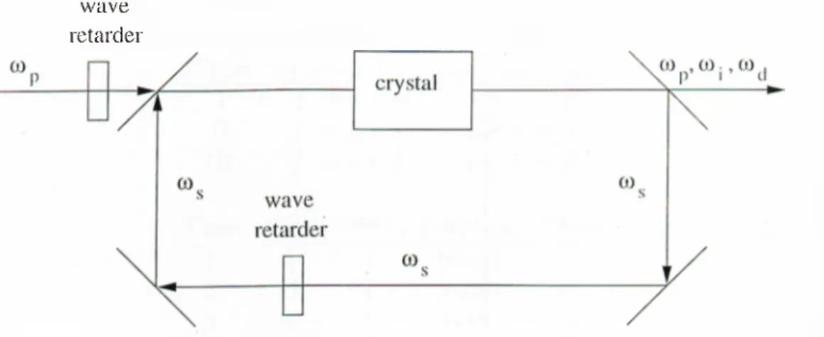
in single crystal sum frequency generating optical parametric oscillators (SF- O PO ’s), parametric generation and SFG are simultaneously phasoi matched for the same direction of propagation [35]. Signal and i)iimp fidds of the OPO process are freciuency summed in the SFG process. The cavity configuration is shown in Figure 4.4. In this configuration, the half wa,ra^ retarder outside the ca,vity provides polarization rotation for the pumi) field if nec(!ssary. Similarly, if a polarization rotation is required for the resonant signal field, it is provided l)y the intracavity half wave retarder before re-injection into the crystal.
w a v e re ta rd e i'
Figure 4.4: Gavity configuration of SF-OPO.
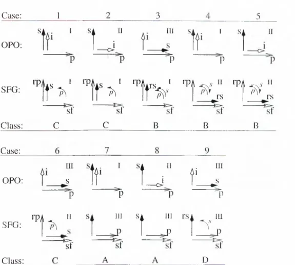
Tlune are three different BPM types for Iroth [)roc(iSses and nine p()Hsil)le combinations of them. These possibilities are shown in Figure 4.5 and Table 4.f. Four different sets of coupled mode equations are re(iuired to dciscribe all nine cases. With QPM, there are eight phase matching typers for each process and a total of 64 different polarization geometries. However, both ])hase matching schemes lead to the same four sets of coupled mode eeiuatious, hence the same four classes [35].
Case; ΟΡΟ; SFG; S i I s L · . “ Ill s 1 s P P Φ, I rPAis ^ I rPAirs Ϊ ΦΑ <χ·ν " ΦΑ --X.V Ί f f i . · ‘7 f ^ · l t > --- ---s f s f Class; C C B ... r s
;^s>
rs B B Case;»
i f
i _ i
f _ s
OPO; SFG; Class; ΦΑ P II%
- ^ P i III ---1 Π i i III ^ P 'P III Ύ A DFigure 4.5; Potential phase matching geometries for the SF-OPO.
OPO SFG
Type ω-i ω]_-\-ω2 (jJ2 + y I f —^ .s -f s s + ,S·
II ./■ +
III S + f ί>· + ./ ./
Case OPO SFG R.otation Class
1 I I pump C 2 II I pump C 3 III I both B 4 I II both B 5 II II both B 6 III II pumi) c 7 I III none A 8 II III none A
9 III III signal D
Class-A
111 c.asiis 7 and 8, the fields with frequencies ω·2 and wa have tln^ sanni direction of ixdarization in both the OPO and SFG processr's. Pohuization rota.tion is not rcKinired for either field. The equations related to the.se ])olari'/a.tion geoituitrirrs ca.n 1)0 derived either by conibining the OPO e(|uations [(.3..33) (.·5.;5Γ))] with tin; SFG ('.(luations [(3.45) (3.47)] or by considering tlu! total iionlin('a,r pohirization fields A and P-.<, at frequencies ω·2 and w.j, resj)ecti\avly, a,nd rri-dcniving the couphrd mode ecinations. The signal a.2 (pump a.a) and tin! lower freciiKincy SFG input a-| (higlK'.r frequency SFG input a,r,) are the same firild mode; the ra,t(! of change! of th(! signal mode is the sum of the rates of change! erf the! OPO signa.l anel the lerweu· freeiuency SFG input fields separately. Similarly, the ra.te! erf ediange! erf the pump mode is the sum of the rates of change erf the OPO pnmir anel the higher freeiuency SFG input fields. The equations gewerning the! he'lels perlarizeel as in these! e;ases are
d(ii
dz (4.1)
da.2
dz = S!att iei;j — «///.;{ei,(i (4.2)
do,\i
İL· = -K„ai(i2 - Κι,α2(ΐ(·, (4.3)
dac,
dz = κ.ι,α2(Η· (4.4)
This SF-OPO is designated as e:lass-A [35].
Exprerssions on the right of Ecinations (4.f) anel (4.4) are! prer|rerrtiernal. Since berth the ieller anel sum frequency fields have zero anqrlituelers a.t the! eaystal en- trane:e, we find that ae(z) = by dehning the ratier [} — Ki,/iia· The range erf values taken by ¡3 depends on the phase rnaterherel freeiuenieies, the! refractive inelie;es, and the effective nonlinear coefficients erf the! twer preretesses. By using this ele!finition, Equations (4.1) -(4.4) are simplified ter [35]
d a .\ — = K„a2(ki (4.0 dz (4.6) di(l2 / ^ o2\ — = [i - β )κ„α\α·2 dz d(l'2, / , ,2 \ —— = — (i + /1 )«!„tt| e;,2· dz (4.7)
The! right hand side erf Equation (4.6) sherws the ediange! in the signal iierlel a,t a,ny va,lne erf .z. I f /1 is unity, the right hanel side erf Eeiuatiern (4.6) is zerrer ferr all values ΟΪ z. In this case, the parametric gain due to OPO prere-.erss is ba,la,ne:e!el by tlu! nern- linerar lerss due to SFG, and the signal fielel amplituele! stays e;ernstant threrugherut the! lenigth erf the eaystal. If/i is less than unity, nernlinerar lerss elue’ ter SFG prere'.erss
is overcome by the parametric gain and the signal held is ampliliiid. Under this condition, the substitutions aj = ui /-^(1 - fP){l + /U), a.2 = 11.2 / \J\ + /U, and a,! = 7/,j / \ / l - (P transform Equations (4.5) -(4.7) to the c(nipled-niod(! e(iuations for a regidar OPA [(3.33)-(3.35)] in terms of tlui varia,bles 7/,|, -uo, a.nd After transforming the OPA solutions [(3.37)-(3.39)] in terms of v/,|, //,7, a,ml v.^ back to tin; original class-A variables a,i, 0,2, and a.^, the (ivolution of tlui ii(4d a,mi)litudes can be expressed as ai{z) = ( φ ) = ( φ ) = ( φ ) = C, { i - β φ + ίβ) c\i{Z„\m„) C, 1 + Λ\\{Ζφ.„) o, V1 - β'^ βα,ι{ζ) - sn{Za\rn„) wh(U(! Cl = {1 - β φ + β φ { ζ ) + (1 - β φ ϋ ζ ) C2 = (1 + //')α.^(^) + (1 -/Ρ)«:^(^) (4.8) (4.9) (4.10) (4.11) (4.12) (4.13) a.r(i the class-A Manley-Rowe conserved quantiti(is [(3.40) and (3.41)] (!Xi)r(!ssed in terms of the held amplitudes 0,1, 0,2, and a , j . Here, m,,, a.nd Z„, ar('. as deiined
in Eciuations (3.42) and (3.43), respectively.
If /1 is larger than unity, the parametric gain due, to OPO proc(!SS cannot conq)c;nsate for the nonlinear SFG loss. In this case, tlui mit gain (!xp(!ri('.nc('.d by l,h(! signal held is always less than or equal to unity, regardless of tin; values of and the input photon hux densities. Therefore, it is impossible for tin; SF-OPO (,o get aI)ove threshold.
Class-B
In cases 3, 4 and 5, the helds at freciuencies (^2 'UkI ηι(· orthogonally polarized
betweiui the OPO and SFG processes. For these helds to ha,v(! two orthogonal components, an extracavity polarization rotation lor tin; pump and a,11 intracavity polarization rotation for the signal helds are necessary. Coupling of tin; two i)io- c(!sses are provided inside the cavity through polarization rotations, not through common helds. The equations
day
da,2 ~dz da,:i dz d(l4 dz d(ir, ~dz d(i(i dz = Ka(i\(k\ = I «2 = -Ki,ar,a,(i = K)()(l/\(lr^ (4.15)
gov(uning this interaction are the OPA and SFG ecgiations [(3.33) (3.35) and (3.45) -(3.47)], separately. This type of SF-OPO’s are called class-B SF-OPO’s [35].
TİK! solutions of these equations are given by Eijnations (3.37) (3.39) and (3.49) -
(3.51) in terms of the Jacobi elliptic functions.
Class-C
In cases 1, 2 and 6, the field i)olarizations at freciuency a;.·! for th(! two processes are orthogonal. The processes are coupled through the field at friupiency u>2·, whereas an extracavity polarization rotation is re{}uired for thci input puiii]) field. Jdui coupled mode eciuations for these cases are
iittj iL· d(l2 dz d(i:i = fk,.a2<h = Kaaia.i - /q,a5«(i = -Kaa\(l2 dz dar, dz dac dz = -K,fttt2a(i = Kfca2«5· (4.23)
This type of SF-OPO’s are labeled as class-C [35]. Tlni iVfanhiy-Rowci lidations a.r(i
O, = a^ i z ) +aHz) - a^(()) (4.25)
C2
=
+ a^(z) + a.f¡(z)= a;j(0) 4-ai^(())
6 3 = a i { z ) + o l { z ) = 0 ( ^ ( 0 ) .
We dehne new variables 0{z) and 7(2:) such that a.\ = \/U\ sind, «,3 = \/C \ cosd, a,r, = \/C3 cos 7, and 0,3 = ^/63 sin 7. Substituting thcisci (ixprcissions into E(iua.- tioiis (4.20) and (4.24), we obtain
, , 1 d,B
0,2(2:) = — —
At,, dz
a.ii(l 7(2:) = P9{z). By inserting expressions for a^iz), a-pz) a,n(l (mAz) into the Manley-Rowe relation for C2, we obtain a single diflerential (i<[ua.tion
2
C2 (4.29)
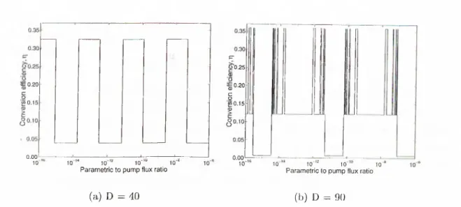
in terms of the variable 0{z). This ecjuation is sniheicmt to (hiserilxi tlui intciiaction for class-C SF-OPO’s and contains information about th(! (iua.lita.tiv(! Ixihaviour of th(! tic'id solutions. If CiCOS^O + C-,iiiuP{P0) can lx‘, hugcir tha,n 62 for any value of 0, 9 oscillates periodically around zero. If [i is a, ralloiial iiumlxu', this coixlition is equivalent to ¿^(O) < «5(0). Then, tlxi signal field is fully (hiphited at each minima and maxima of 9 and the held a.mplitud(is (!volv(i pcuiodically. If C\ cos^ (9-1-63 siiP(/i0) is less than or eipial to C2 for all 9 vahuis, them 9 increases monotonically. The held solutions are i)eriodic if (j is rational, tlxiy are ape.riodic otlx'i'wise [35].
Although Equation (4.29) contains useful information al)out the ciualitative l)ehavior of the solutions, we prefer to solve Eciuations (4.20) (4.24) directly. Eviuy time the signal held gets fully depleted, d9/dz diang(is sign. Sim:e the first t(!rm of Equation (4.29) is quadratic and tlxu-eforci has an ambiguity about the sign oi d.9/dz, this sign change has to be taken into account.
Class-D
In cas(! 9, the held polarizations of OPO and SFG proc(!sses at frcxiuency a,r(! orthogonal. An intracavity polarization rotation is rixiuired for this held. OPO pump held has the same polarization diniction as tlx', high fr(xiuency SFG input 11(4(1 and providcis the coupling between the two proc(!Sses. Tlx; e(]ual,ions gov(irning this interaction are
da\ Ί Ι da,2 dz da-2 dz da,i I h dae dz
This (4ass of SF-OPO’s are called class-D [35]. The Manl(!y-Row(( r(4ations are = GAdfd = - « „0-10,2 - «1,0-10(i -«1,θ3θ(; = «ί,θ3θ4. (4.30) (4.31) (4.32) (4..33) (4..34) C\ = α ξ { ζ ) - α ϋ ζ ) = 0^(0) C-2 = (>‘2{^) d-(I'iiz) -l· aif^z) = 0,2(0) + ((-3(0) (4.35) (4.36)
Qi = a i { z ) + a l ( z ) = aj(0) (4.37)
VV(i cleiine new variables 6{z) and j{z) throngh a,i = ^/C~\ siidi d, ao = \/U[ cosh 0, r/,4 = \/C^ CO S 7, and ag = \/C3 sin7. Snbstitntion of flnisc! (ixpvessions into the
conpled-inode equations (4.30) and (4.34), yields the pump held amplitude in terms of 0[z) or 7(2;) as
. . 1 (].f) I fir/
(4..38) tt (z) — ^ ^
Ka dz Ki, dz
Inserting expressions for a2{z), 0,3(2:) and a,(s{z) into the Manley-Rowe relation for C2, we obtain a single differential equation
2
7, (4.39)
1 id e '
— j + Cycosh" e + C\sin" ( / i d ) = c \
in the variable 0{z). Initially, 0{z) is zero at the crystal entranc:e. The second term in Ecpiation (4.39) increases rnonotonically until df)/dz bec.omes zero. This point corresponds to fidl depletion of the pump field as seen from E(}na,tion (4.38). Since tlie first term of Equation (4.39) is non-negative, f)(z) has to decriiase from this point on. Hence, 0 oscillates periodically around zero, and the field amplitudes a.lso evolve periodically. As in class-C single-])ass solutions, we ])refer to solve the original conpled-rnode equations [(4.30)-(4.34)] in comi)nting the single-pass signal gain.
4.2.2
Self-Doubling Optical Parametric Oscillators
Self-doubling optical parametric oscillators (SD-OPO’s) (unploy a singh; crys tal in which parametric generation and SHG processes air; simultaneonsly phase matched for the same direction of propagation [34]. The SIIG process produces ladiation at twice the frequency of the signal field of the i)arametric generation |)iocess. The configuration of a SD-OPO ring cavity is shown in Figure! 4.G. The
CO P SD-OPO \ \ p’ CO , CO . , CO ,1 ’ CIS _________________________________
7
c r y s t a l\
CO s w a v e COs re ta rd e r\
AT
/
Figure 4.6: Self-doubling OPO cavity configuration.