PROCEEDINGS OF SPIE
SPIEDigitalLibrary.org/conference-proceedings-of-spieMetamaterial-based cloaking with
sparse distribution of spiral
resonators
K. Guven
E. Saenz
R. Gonzalo
E. Ozbay
S. Tretyakov
Metamaterial based cloaking with sparse distribution of spiral
resonators
K. Guven
*,a, E. Saenz
b, R. Gonzalo
b, E. Ozbay
c,
and S. Tretyakov
da
Department of Physics, Koç University, Sarıyer 34450, Istanbul, Turkey
b
Electrical and Electronic Engineering Department, Public University of Navarra, Campus
Arrosadia, E-31006 Pamplona, Spain
c
Department of Physics & Department of Electrical and Electronic Engineering, Bilkent University,
Bilkent, 06800 Ankara, Turkey
d
Department of Radio Science and Engineering, Helsinki University of Technology, FI-02015 TKK,
Finland
ABSTRACT
We investigate the application of a metamaterial that is formed by the sparse distribution of spiral resonators as an optical transformation medium is in order to achieve electromagnetic cloaking. The well-known Clausius-Mossotti formula relates the microscopic polarizability of a single resonant particle to the macroscopic permittivity and permeability of the effective medium. By virtue of transformation optics, the permittivity and permeability of the medium, in turn, can be designed according to a coordinate transformation that maps a certain region of space to its surrounding. As a result, the mapped region can be cloaked from electromagnetic waves. In this study, the spirals are optimized to exhibit equal permittivity and permeability response so that the cloak formed by these spirals will work for both the TE and TM polarizations. An experimental setup is developed to visualize the steady state propagation of electromagnetic waves within a parallel plate waveguide including the cloaking structure. The measured and simulated electromagnetic field image indicates that the forward scattering of a metal cylinder is significantly reduced when placed within the cloak.
Keywords: Electromagnetic Cloaking, Transformation Optics, Metamaterial, Spiral resonator.
a [email protected], phone: +90 212 3381697; fax: +90 212 3381559; www.ku.edu.tr Invited Paper
1. INTRODUCTION
Metamaterials are artificial structures that can be designed to have a particular permittivity or permeability response to an incident electromagnetic wave at the desired frequency range. Consequently, the propagation of electromagnetic waves within a metamaterial can be controlled to a greater extend. This ability has given rise to a new research field known as transformation optics. A recent outcome in this field was the realization of the electromagnetic cloaking effect by a conformal mapping metamaterial medium, which compresses the interior space of a cylindrical region 0 < ρ < a into the surrounding cylindrical shell a< ρ < b [1, 2]. In the “transformed” space, the electromagnetic waves propagate as in free space, whereas they are moving around the cylindrical region in real space. In other words, the cylindrical region is “hidden” in the transformed space. Consequently, for an opaque object placed inside the cylindrical region, no scattering occurs in the propagating wave that may indicate its presence. The object is rendered invisible.
The realization of this elegant idea was reported first for TE polarized waves in 2006 [3]. The cloak design is based on concentric shells occupying the region a < ρ < b, which are decorated with magnetically resonant split ring resonators (SRRs) whose geometrical design parameters are individually determined according to the transformation. Soon after, a non-magnetic design was proposed theoretically for TM-polarized waves at the optical regime, which is based on radially oriented metallic wires [4]. Since then many studies are published in the literature, exploiting the theoretical and experimental aspects of the electromagnetic cloaking phenomenon. These studies eventually formed a novel research field known as the transformation optics, in which cloaking now appears but one of the many possibilities to sculpture the path of the light.
Transformation optics is based on the idea that the Maxwell’s equations preserve their form under a coordinate transformation provided that the permittivity and permeability of the medium are transformed accordingly. This implies that if a medium is constructed with particular permittivity and permeability values (corresponding to a distorted coordinate system) the electromagnetic field takes up the distorted configuration in the medium. Formally, under a particular coordinate transformation
q
′
(j′)( )
q
j the permittivity and permeability are transformed as follows in order to preserve the form of Maxwell’s equations:,
)
det(
,
)
det(
) ( ) ( ) ( ) ( ij j j i i j i ij j j i i j iε
μ
μ
ε
Λ
Λ
Λ
=
′
Λ
Λ
Λ
=
′
′ ′ ′ ′ ′ ′ ′ ′ where ( ) ) ( j j j jx
x
∂
∂
=
Λ
′ ′ is the Jacobian. The pioneering work in Ref. [3] employs a coordinate transformation is of the form,.
;
;
z
z
a
b
a
b
=
′
=
′
+
−
=
′
ρ
ϕ
ϕ
ρ
(1).
;
;
2ρ
ρ
μ
ε
ρ
ρ
μ
ε
ρ
ρ
μ
ε
ρ ρ ϕ ϕa
a
b
b
a
a
z z−
⎟
⎠
⎞
⎜
⎝
⎛
−
=
=
−
=
=
−
=
=
(2)With this radial dependence of all components, the realization of the cloak is a difficult task. The set of relations shown in Eq. (2) can, however, be simplified so that the ray trajectories inside the cloak remain the same as for the “full design.”[3] Further simplification is achieved by considering a single polarization for the incident field. For TE (TM) polarization, it can be shown that a gradient of μρ (ερ) suffices to generate a significant cloaking effect.
In the present paper, we investigate the realization of a dual-polarization cloak at microwave frequencies by employing canonical spiral particles. [5] As opposed to employing other resonant particles with different geometrical parameters this design uses a single type resonant particle. By employing canonical spirals with the same dielectric, magnetic, and chiral susceptibilities, cloaking can occur for both TE and TM polarized incident electromagnetic waves. The chirality of spirals can be compensated for using a racemic mixture of left- and right-handed spirals in the cloak design [6]. Moreover, since both electric and magnetic response is provided by the same particle, it is possible to design metamaterial with nearly the same frequency dispersion of permittivity and permeability [5], realizing broadband matching. In section II, we begin by describing the design and the electromagnetic response of canonical spiral particles. In section III, the design of the metamaterial cloak is described in detail. The simulation and experimental results of the metamaterial cloak are given in section IV.
2. CANONICAL SPIRALS
2.1 Polarizability of the canonical spirals and the effective permittivity and permeability
The schematic view of a right-handed canonical spiral is given in Fig. 1 (a). It consists of a split loop wire with two straight wires extending from the split, normal to the plane of the loop. Figure 1(b) shows a photograph of the manufactured spiral which is resonant at f = 8.0 GHz.
The currents induced in the spiral generate an electric dipole (the wire) and a magnetic dipole (the loop). By adjusting the design parameters (dipole length, 2l, loop radius, R, and the radius of the wire, r0), the electric and magnetic
responses of the particle can be tuned to be identical [6]. Another spiral design is known as the helix where the straight wire components are absent and the loop is streched along the vertical, determined by a certain pitch angle (Fig. 1(c)).[6] We adopt the simplified conditions given in Ref. 2 that can be satisfied for ε and μ simultaneously with the canonical spirals. Equation (2) can be modified in the following way [5]
.
;
2a
b
b
a
a
b
b
z z−
=
=
=
=
⎟⎟
⎠
⎞
⎜⎜
⎝
⎛
−
−
=
=
ε
μ
ε
μ
ρ
ρ
μ
ε
ρ ρ ϕ ϕ (3)Figure. 1: (a) Geometry of the canonical spiral. Design parameters are the radius of the loop, R, the length of the arms, l, the radius of the wire, r0, and the pitch, h. (b) A photograph of one manufactured spiral resonant at f = 8.0 GHz (λ = 3.75 cm). (c) Geometry of the
helix. The pitch angle defines the pitch in one turn.
Primarily, we focus on satisfying the condition for the radial parameters ερ = μρ. The relative permittivity and permeability of a sparse mixture can be approximated using the Clausius-Mossotti formula (e.g. [6]),
.
3
1
Re
1
;
3
1
Re
1
0 0n
n
n
n
m r e r−
⎭
⎬
⎫
⎩
⎨
⎧
+
=
−
⎭
⎬
⎫
⎩
⎨
⎧
+
=
α
μ
μ
α
ε
ε
(4)where αe and αm are the electric and magnetic polarizabilities, respectively, of a single inclusion, and n is the inclusion
density per unit volume. By demanding εr = μr, we find that the polarizabilities must satisfy
α
e/
ε
0=
α
m/
μ
0.The effective material parameters are implemented by the spiral particle, which consists of an electric dipole and a magnetic dipole. The axial polarizabilities of the spiral are [7-8]
( )
.
1
1
2
)
2
/
tan(
4
sin
cos
1
cos
1
cos
sin
0 0 1 3 0⎥
⎦
⎤
⎢
⎣
⎡
+
+
−
=
⎥
⎥
⎥
⎥
⎦
⎤
⎢
⎢
⎢
⎢
⎣
⎡
+
−
−
−
−
=
A
Y
Y
j
A
kR
J
R
jwkZ
kl
Z
Z
Z
kl
k
kl
kl
kl
l
k
kl
W L m W L W l eπη
π
μ
α
α
(5)where ZW and ZL denote the impedances and YW and YL denote the admittances of the wire and the loop, respectively.
These values as well as the details of derivation can be found in Ref. [8].
Evidently, the operational frequency of the cloak should be close to the resonant frequency of the spirals in order to excite the dipoles. By requiring Re{αe/ε0} = Re{αm/μ0} at the resonant frequency, when Im{YW} = -Im{YL}, the optimal dimensions of the spiral can be obtained. The axial and azimuthal components εφ = μφ = εz = μz = b/(b - a) are all equal
and constant. We assume that the response of the spiral in the transversal plane (the plane of the loop) is much weaker than in the axial plane, the inclusions will not affect very much those components, in which the corresponding permittivities and permeabilities are determined by the background material. If we further design the cloak such that b >> a, the values of the permittivity and permeability become close to unity. In that case, air is a suitable background material.
For the selected operation frequency of 8 GHz, the optimum spiral dimensions are R = 1.95 mm, l = 2.85 mm [9]. We note that the size of the particles are in subwavelength scale (2l/λ < 1/6). The particle size defines the ultimate lower limit on the spatial separation between the particles. Therefore, miniaturization of the resonant particle is crucial so that a more uniform distribution of resonant particles and consequently a smoother spatial transition of the permittivity and permeability functions can be realized.
The real and imaginary parts of αe/ε0 calculated for R = 1.95 mm and l = 2.85 mm are shown in Figure 2.
Figure 2: The ratio αe/ε0 computed as a function of frequency for the optimum dimensions R = 1.95 mm and l = 2.85 mm.
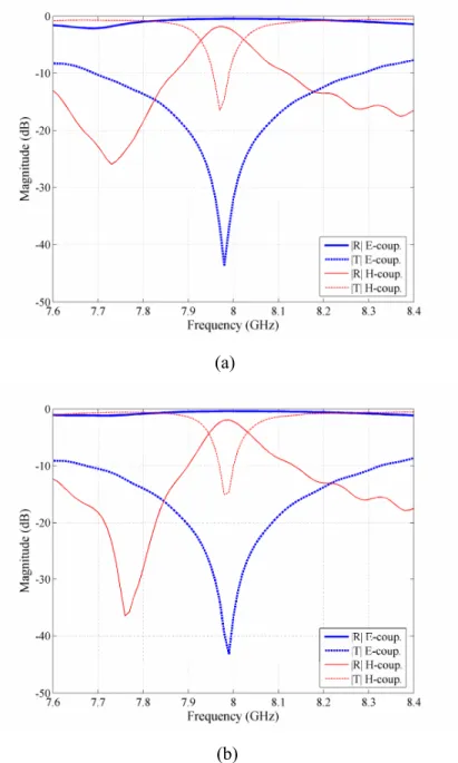
2.2 Reflection and transmission coefficients of the canonical spiral for E and H-coupling
The reflection and transmission spectra of the helix were determined by the S-parameter measurements of a single spiral placed inside the end-to-end joined two waveguide adapters and excited by the TE10 mode. In the E-coupling
measurements, the axis of the spiral is parallel to the incident electric field so that the spiral is seen as an electric dipole. The current induced in the loop also causes a magnetic dipole. However, the magnetic field of this induced dipole is now
also y-directed and it cannot excite a propagating wave in TE10 mode. In the H-coupling measurements, the incoming
magnetic field penetrates the loop of the spiral in turn creating a magnetic dipole. In this case, the secondary electric field, which is excited by the current induced in the "legs" of the dipole, is perpendicular to the TE10 mode and thus
unable to propagate.
In the measurements, the right-handed (RH) and left-handed (LH) spirals were tested under E and H-coupling excitations. Both RH- and LH spirals were tuned to the resonant frequency (f ≈ 8 GHz) as can be seen for both polarizations in Figure 3.
(a)
(b)
3. THE ELECTROMAGNETIC CLOAK STRUCTURE
In the proposed cloaking device, the radial alteration of permittivity, ερ, (Eq. 3) is implemented by changing the inclusion density n as a function of the radial distance ρ. In the earlier work, the geometrical parameters of the resonant particle are modified according to the radial position of the particle [3,4]. By imposing ερ (Eq. 3) equal to εr (Eq. 4), the density of inclusions as a function of the relative permittivity can be expressed as,
.
2
1
3
0⎟⎟
⎠
⎞
⎜⎜
⎝
⎛
+
−
=
r r en
ε
ε
α
ε
(6)On the surface of the inner cylinder, ρ = a, ερ must go to zero, which means the value of αe must be negative and
sufficiently large. By choosing αe/ε0 close to the resonance (αe/ε0 = -0.5·10-6 m3), the density of the inclusions n can be
calculated as a function of the radial component of the permittivity.
The cloak is formed by concentric cylindrical shells that are separated by a distance Rdiv (see Figure 4). Rdiv is set equal
to 1 cm. For a three-dimensional cylindrical cloak, the layers should be stacked onto each other with an interlayer separation of 1 cm. Taking into account these unit cell dimensions, the number of canonical spirals per row Nρ can be
calculated to satisfy the required spiral density.
The radial distance ρ, permittivity ερ, density of inclusions n, the exact number of spirals per row Nρ and the even integer
number N'ρ that is used in the design are all shown in Table I. A schematic of the final cloak design is shown in Figure 4. Table 1: Number of inclusions of the cloak operating at 8 GHz and αe/ε0 = -0.5·10-6 m3.
Row ρ (cm) ερ n (cm-3) Nρ N ρ′ 1 2 0.08 2.66 16.72 18 2 3 0.31 1.78 16.81 16 3 4 0.49 1.23 15.5 16 4 5 0.61 0.89 13.98 14 5 6 0.70 0.66 12.42 12 6 7 0.77 0.49 10.87 12
For a cloak structure in free space, a racemic mixture of canonical spirals is required to compensate for the chirality [9], which means an equal number of RH and LH spirals per unit cell. Therefore, the number of inclusions on each row must be even. Interestingly, when the cloak is placed in a parallel plate waveguide, the chirality is compensated for by mirror imaging from the plates of the waveguide. Hence, in principle, only the spirals of one handedness could be used to construct the cloak within a parallel plate waveguide.
Figure 4: Schematic of the 2D cloak showing the distribution of spirals. Parameters are a = 1.5 cm, b = 7.5 cm, Rdiv = 1.0 cm.
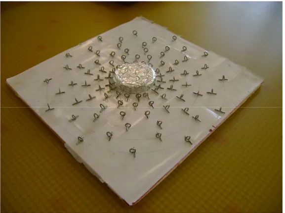
The experimental cloak structure is shown in Figure 5 where a racemic mixture of canonical spirals is used.The spirals are placed on a styrofoam pad around the cloaking region, which contains a metal cylinder.
4. EXPERIMENTAL TECHNIQUE 4.1 The electromagnetic field imaging setup
The cloak structure was measured in a two-dimensional parallel plate waveguide fed with a coax-to-waveguide adapter excited by the TE10 mode. The upper plate of the waveguide is patterned by a grid of sub-wavelength holes. The radius
and lattice constant of the holes were 1.5 mm and 3.5 mm, respectively. The dimensions were selected such that the plate forms a low impedance grid and, therefore, it does not disturb the field inside the waveguide. However, the leaky field (around -20 dB) that radiates through the holes can be detected. A monopole antenna that is mounted on a 2D scanning stage detects the real and imaginary parts of the leaky field. The source and detector are connected to an HP8510C network analyzer. The full 2D map of the electromagnetic wave can then be constructed from the measurement data. The edges of the parallel plate waveguide are isolated by microwave absorbing pads in order to prevent any possible reflection from the open ends. A photograph of the waveguide interior including the cloak is shown in Figure 6.
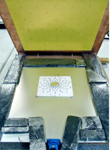
Figure 6: The cloak measurement setup. The upper plate of the parallel-plate waveguide (lifted to show the interior) is made of a metallic grid on a dielectric plate. The cloak is placed in the middle of the waveguide. The sides of the waveguide are covered with
microwave absorbers. The coax-to-waveguide adapter feed is shown at the bottom.
The phase of the field is referenced to the output port of the network analyzer. The advancement of the field can be generated by applying an arbitrary phase factor φ in
E
(
x
,
y
)
e
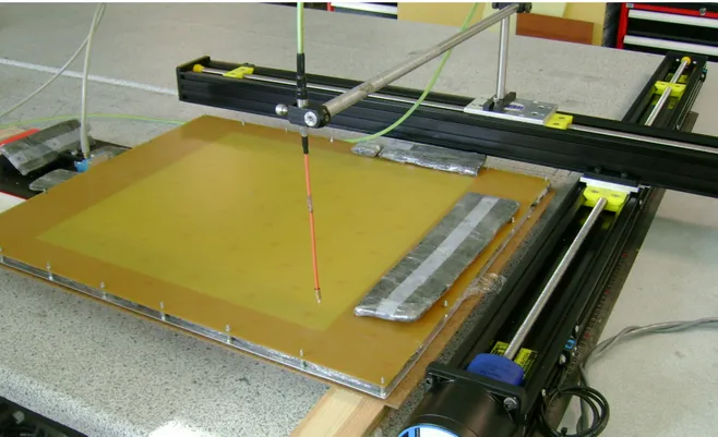
jφ[10].Figure 7: The experiment setup to image electromagnetic field. A probe antenna mounted on a 2D stage measures the leaky field from the metal grid comprising the top plate of the parallel plate waveguide. The waveguide adapter on the far left provides the input field.
Figure 8: The real part of the electromagnetic field propagating within the empty waveguide at f = 8.0 GHz. The input waveguide is located at x = 0.0 cm, y = -15 cm.
In order to qualify the experimental setup for measurements, we first imaged the steady state propagating mode of the empty parallel plate waveguide. The measured real part of the complex electric field at f = 8.0 GHz is shown in Figure 8.
Evidently, the propagation does not develop into perfectly planar wavefronts due to the limited distance from the feeding waveguide port, but does manage to provide a good mode profile to investigate the cloaking effect.
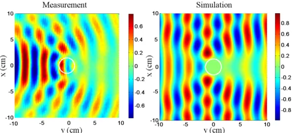
4.2 Measurements and simulations of the bare metal cylinder
The object that is to be cloaked is a metal cylinder that is 3 cm in diameter and 1 cm in height. The bare metal cylinder (marked by the small circle shown in ) is placed in the waveguide and the 2D map of the electromagnetic field is measured. For a comparison, we also simulated the experimental structure using a commercial full wave 3D electromagnetic solver. The real part of the measured and simulated electric field is shown in Figure 9 (a) and (b), respectively. It is noteworthy that the experimental field map is constructed from the leaky field “above” the top plate of the waveguide. This generates the presence of a spurious field above the metal cylinder. In addition, since the incident wavefronts are not perfectly planar, the scattering pattern bears a similar bending. In the simulations, the electric field data is recorded on the bisecting plane inside the waveguide. We observe that the measurement and simulation are in good agreement, demonstrating the shadow behind the cylinder due to forward scattering and a standing wave formation between the feeding port and the cylinder due to backward scattering.
Figure 9: The real part of the measured and simulated electric field inside the waveguide in the presence of the metal cylinder.
4.3 Measurements and simulations of the cloaked metal cylinder
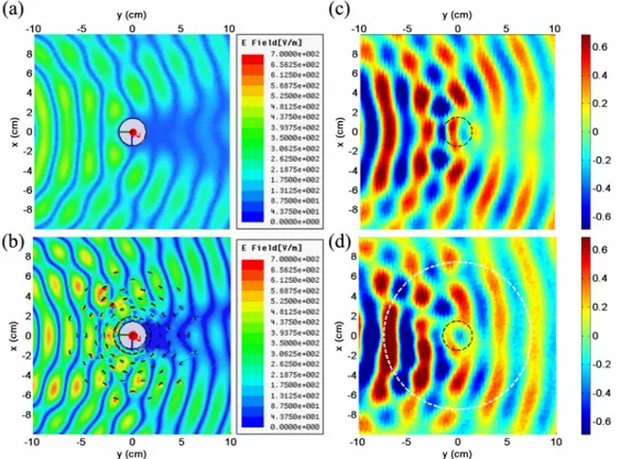
The simulation of the cloak with the metal cylinder is computed by a commercial numerical software (HFSS). Figure 10
(a) and (b) show the absolute value of the electric field amplitude that is taken on the parallel bisecting plane inside the waveguide. The localized resonance modes of the canonical spirals are apparent in this simulation. We observe that in the presence of the cloak, the shadow behind the cylinder gets reduced past the cloak boundary where the partial restoration of the electric field is apparent. The backscattering is not completely eliminated either, but this is anticipated due to the approximations made in the design and fabrication of the cloak.
Figure 10 (c) and (d) show the measured real part of the electric field for the bare and cloaked cylinder. The spatial resolution of the measurement is limited by the grid spacing of the top plate which cannot be made arbitrarily small since the amplitude of the leaky field decreases rapidly. As a result, the leaky component of the field in the grid holes gives a low-resolution image of the actual field profile inside the waveguide. While this may be a drawback against imaging the local field around a particular canonical spiral particle, the overall back- and forward scattering features are clearly visible. On the other hand, the simulations require a spatial resolution smaller than the gap of the canonical spirals in order to generate the correct electromagnetic behavior of the spirals. Evidently, the simulation and the experimental plots are intended only for qualitative comparison about the cloaking phenomenon.
The experimental result indicates that the wavefronts are starting to restore in the shadow area in the presence of the cloak. Moreover, an encircling behavior of the field around the inner boundary of the cloak can also be observed which hints the exclusion of the field from the core region of the cloak. However, the loss inherent to the resonance of the spirals inevitably causes a decrease in transmission amplitude through the cloak. Thus, the overall contrast is reduced in the presence of the cloak.
Figure 10: The simulated electric field amplitude of the (a) bare and (b) cloaked metal cylinder (grey circle). The canonical spirals of the cloak are indicated in black. The measured real part of the electric field of (c) bare and (d) cloaked meta l cylinder. The dashed
black line denotes the cylinder location and the dashed white line denotes the outer boundary of the cloak.
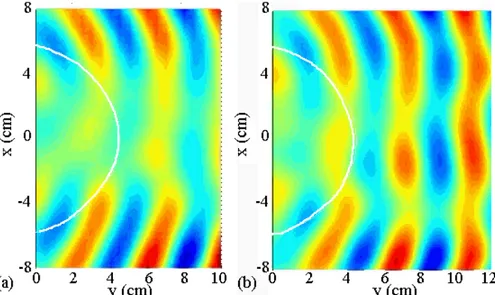
We further carried a high resolution scan in a rectangular region behind the cloaked cylinder. In order to probe the signal as local as possible, the probe antenna is placed within a movable pad made from microwave absorbing material. The
entire top surface of the waveguide except the scan region is covered with microwave absorbers to reduce the background noise. Figure 11 shows that in the absence of the cloak, the forward scattering of the metal cylinder produces a clear shadow area. When the metal cylinder is surrounded with the cloaking structure, the wavefronts are restored into nearly freespace propagation.
Figure 11: Real part of the electric field distribution in a rectangular region behind the metal cylinder (a) without and (b) with the cloak. The back edge of the cylinder is located at x = 0, y = 0. The white line indicates the boundary of the cloak.
5. CONCLUSION
We investigated the cloaking ability of a metamaterial medium formed by canonical metal spirals experimentally and by numerical simulations. The radial change in the permittivity, ε, is realized by modifying the inclusion density of spirals as a function of the radial distance. By using a parallel plate waveguide that incorporated an upper metal grid, the imaging of the propagating field in the presence of the bare metal cylinder and cloaked cylinder was obtained. A comparison of the field images indicates that the cloak manages to reduce the scattering and restoration of the field to the empty-waveguide-mode past the cloak. The cloak design is based on the formulation given by Eq.s (4) and (6). Evidently, the sparse distribution of resonant particles based on the simplified transformation can approximately provide the desired smooth transition of the effective parameters. Increasing the particle density can improve the uniformity of distribution provided that the governing transformation equations are still satisfied.
Acknowledgments
This work is supported by the European Union under the projects METAMORPHOSE, PHOREMOST, EU-PHOME, and EU-ECONAM, and TUBITAK under the Project Numbers 105E066, 105A005, 106E198, and 106A017. The authors E. O. and K. G. acknowledge partial support from the Turkish Academy of Sciences.
REFERENCES
[1] Pendry J. B., Schurig D., and Smith D. R., “Controlling electromagnetic fields,” Science 312, 1780–1782, (2006). [2] U. Leonhardt, “Optical conformal mapping,” Science 312, 1777 - 1780 (2006).
[3] Schurig D., Mock J. J., Justice B. J., Cummer S. A., Pendry J. B., Starr A. F., and Smith D. R., “Metamaterial electromagnetic cloak at microwave frequencies,” Science 314, 977–980, (2006).
[4] Cai W., Chettiar U. K., Kildishev A. V., and Shalaev V. M., “Optical cloaking with metamaterials,” Nature Photonics
1, 224–227, (2007).
[5] Guven K., Saenz E., Gonzalo R., Ozbay E., Tretyakov S., “Electromagnetic cloaking with canonical spiral inclusions,” New J. Phys. 10, 115037 (2008).
[6] Tretyakov S., [Analytical Modeling in Applied Electromagnetics], Norwood, MA, Artech House, (2003).
[7] Tretyakov S. A., Maslovski S., and Belov P. A., “An analytical model of metamaterials based on loaded wire dipoles,” IEEE Trans. Antennas Propag. 51, 2652–2659, (2003).
[8] Tretyakov S. A., Mariotte F., Simovski C. R., Kharina T. G., and Heliot J. P., “Analytical antenna model for chiral scatterers: Comparison with numerical and experimental data,” IEEE Trans. Antennas Propag. 44, 106–1014, (1996). [9] Saenz E., Semchenko I., S. Khakhomov S., Guven K., Gonzalo R., Ozbay E., Tretyakov S., “Modeling of Spirals with Equal Dielectric, Magnetic, and Chiral Susceptibilities,” Electromagnetics 28, 476-493 (2008).
[10] Justice B. J., Mock J. J., Guo L., Degiron A., Schurig D., and Smith D. R., “Spatial mapping of the internal and external electromagnetic fields of negative index metamaterials,” Optics Express 14, 8694–8705, (2006).
[11] Cai W., Chettiar U. K., Kildishev A. V., Shalaev V. M., and Milton G. W., “Nonmagnetic cloak with minimized scattering,” Appl. Phys. Lett. 91, 111105 (2007).