Proceedings of the I996 IEEE
International Conference on Robotics and Automation Minneapolis, Minnesota
-
April 1996Location and Curvature Estimation of “Spherical” Targets using
a
Flexible Sonar Configuration *
Billur Barshan
Department
of
Electrical Engineering
Bilkent University
Bilkent, 06533 Ankara, Turkey
Abstract
A novel, flexible, three-dimensional (3-D) multi- sensor sonar system is employed t o localize the center of a spherical target and estimate its radizls of curva- ture. The interesting limiting cases for the problem under study are the point and planar targets, both of which are important f o r the characterization of a mo- bile robot’s environment. A noise model is d e v e l o p e d based on real sonar data. An extended Kalman filter ( E U F ) which incorporates the developed noise model is employed as an estimation tool for optimal process- ing of the sensor d a t a . Simulations and experimental results are provided for specularly reflecting cylindrical targets.
1 Introduction
Although most of today’s mobile robots are operat- ing in 2;-D environments, 3-D target recognition and discrimination of targets has potential significance for robots operating in 3-D environments such as airborne robots or robots designed for underwater applications. Recently, several researchers have started investigat- ing the limitations of sonar for 3-D target recognition and tracking. In [l], the minimum amount of infor- mation and actuation needed to track a ball in 3-D has been determined and implemented using qualita- tive methods only, without quantifying and modeling any of the unknown parameters of the target. Hong and K l e e m a n have i n v e s t i g a t e d the g e o m e t r y of 3-D
corner cubes using a low-sample rate equilateral trian- gular sonar configuration [ 2 ] . Kleeman and Akbarally
have classified and discriminated the primitive target types commonly occurring in 3-D space [3]. Peremans et a1 [4] and Sabatini [5] have both investigated curved reflectors using a linear array configuration.
The aim of this paper is to estimate the unknown ‘This work was supported by T U B I T A K EEEAG-92 project and t h e British Council Academic Link Program.
parameters of “spherical” targets in 3-D. In the next
section, a detailed description of the sensing device is given. In Section 3, the geometry of reflection from a spherical target is considered and analyzed. The re- sults for the limiting cases of point and planar targets are highlighted. In Section 4, these analytical results together with a correlated noise model are incorpo- rated in an EKF to estimate target location and radius
of curvature. Simulations and experimental results are provided in Section 5. Concluding remarks are made in the last section.
2
The
Sensing Device
The sensing device used in this investigation was constructed very accurately for 3-D sonar applica-
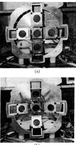
tions. A trade-off between simplicity of mechanical de- sign and flexibility was established. Th e unit consists
of five Polaroid transducers, each operating at a reso- nant frequency of f0=49.4 kHz, where a single, central transducer is flanked by four receivers configured like the petals of a flower. The central transducer is fixed but the separation d between the central transducer and each surrounding one can be manually adjusted to any value from 5 t o 15 cm. The device has 16 me- chanical joints which enables it t o move with the aid
of a single stepper motor mounted behind the central transducer. In one extreme position, all the sensors are coplanar which corresponds t o the reference point of the stepper motor. In the other extreme, the middle transducer is pulled back by 7.5 cm due t o the displace- ment caused by turning of the stepper motor. These two extreme positions are illustrated in Figure l a and b. In Figure l b , the angle between the horizontal plane and the surrounding transducers is 30’. In between, the stepper motor can take 1020 steps with step size
0.9”. The flexibility of the sensor can be judicuously used in order to recognize 3-D targets and focus on them to extract valuable information from the sensed data.
-
h, = ctr =
dr2
+
d 2 - 2 d r c o s4 si n B - R 2(b)
Figure 1: Two extreme positions of the sensing device.
The system is flexible enough that the transducers can be fired in any sequence. In the firing pattern selected, each transducer transmits and receives the echo of its own signal. Assuming the target is station- ary, this can be done sequentially to avoid crosstalk between the transducers. After each transmission, the detected waveform is recorded and a TOF reading is obtained by thresholding.
3
Target Reflection Geometry
A stationary spherical target of radius R is assumed t o be present at spherical coordinates ( r , 8,4).
3.1
From the geometry of Figure 2, the round-trip dis- tance measurements a t the surrounding transducers are:
Spherical Target with radius
R
ct 0 2 - = r - R h , = h[ z - =
"'
J r 2+
d 2+
2dr cos 4 sin t9 - R 2where t o , t,, t l , t,, t d are the TOF values from the
transmitter to the middle, right, left, g p and down
transducers respectively, and e is the speed of sound in free space. Each measurement confines the target lo-
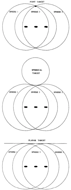
cation to a circle centered at 1 he corresponding trans- ducer. At least three measurements are ecessary to identify the curvature of the target both in 2-D and 3-D. This is illustrated in Figures 3 and 4. To localize the center of the target with finite radius, one needs three measurements in 2-D and five in 3--D as indi- cated by the expressions for the true polar coordinates of the target:
-d d -
(TOP VIEW)
SPHERICAL TARGET
m
POINT TARGETPLANAR TARGET^^)
Figure 3: T he indeterminacy of curvature with only two measurements. The unknown target can have any curvature from zero t o infinity.
3.2
Point Target:
the
limit
R
t0
In the limit as R + 0, a point target is obtained. Point target localization in 2-D has been considered in [6] and two methods of estimating the location have been presented using a linear array of transducers. The equations in 3-D derived above for finite R become simpler in the limit as R ---$ 0:
Characterizing the point-target response of a sen- sor is important not only for its application to point targets but also t o assess its performance on extended targets. There are different approaches t o model ex- tended targets in robotics applications [2, 4, 71. If
the approach is one of hypothesis testing or one of parametrizing the extended target, then sensor per- formance may not be easily related t o its point-target response. On the other hand, for extended targets of unknown shape with possible roughness
[$I,
point tar- get analysis can be extremely useful.3.3
Planar Target: the limit
R
--+ 00For the limiting case of R -+ 00, the target be- comes a plane. Both the distance to the center of the “sphere” and its radius of curvature become infinity. In this case, either the limits of the above equations can be taken carefully or, more simply, the perpendic- ular distances of the transducers to the plane can be
SPHERICAL
PLANAR TARGET
Figure 4: The geometry of point, spherical and planar targets for three measurements. Three measurements uniquely identify the curvature of the unknown target both in 2-D and 3-D.
I
11
R = 5 c m11
R = 3 0 c m11
R =n
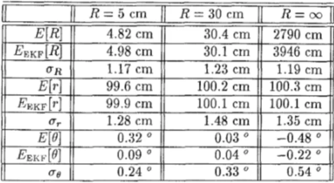
~ Em1;
E E K d R I U 4.82 cm 30.4 cin 2790 cm 4.98 cm 30.1 cm 3946 cm E E K , [ 4 U $Table 1: Experimental results.
directly derived from the geometry as:
0.09
'
0.04' -0.22'
0.24 ' 0.33 ' 0.54'
h, hi hu hd The solution is:8 = = h ,
-
dcosq5sin8 = h, +dcosq5sin8 = h ,-
d s i n 4 = h ,+
dsinq5 h , + R = c o asin hr - hr J4d2 - (hd - h u ) 2 hd-
hu asin-
2d (4) (5) The distance t o the surface of the plane is simply h ,4
Estimation
of Target
Posit ion
In real sonar systems, there are three principal com- ponents of noise, which are thermal noise in the re- ceivers, variations in the velocity of sound c , and acoustic amplitude fluctuations due to air-temperature variations [5]. These effects can be effectively mod- eled by two different noise components: First, there is the rapidly varying and uncorrelated noise component, which is amplitude dependent. It represents the errors due to quantization of the received waveforms, time- sampling of the signal and thermal noise of receiving circuit electronics. The second noise component varies more slowly in time compared t o the first, and is highly correlated. The main contributing factor is the mo- mentary fluctuations of the speed of sound in air due to temperature, humidity changes and drafts of air, encountered very frequently in typical indoor environ- ments. Such macroscopic environmental changes affect all five measured distances similarly, causing s p a t i a l
correlation between the receivers.
These effects were modeled by using a covariance matrix with constant spatial correlation between the
measurements. With the additive noise incorporated, the noiseless measurement equations given in Equa-
tions l become:
z(k) = h[@(k)]
+
v ( k ) (6) where v(k) is the measurement noise process veclor.Since the observation model is nonlinear, an EKF is used to filter the noisy d a t a and obtain estimates for @ = (R, r , 8, q ! ~ ) ~ . A first-order approximation to the function h( .) is made by first finding its Jacobian Vh. This is used to update the covariance matrices as de- scribed in [9].
The states that need t o be estimated are the true values of R, T , 8 and
4.
The resulting state equationsfor a stationary target are as follows:
or in matrix notation:
@(/k
+
1) = @ ( k )+
w(k). (8)The process noise represents any deviations from the assumed model of state evolution, described by the state equation above, and is assumed t o be zero- mean and white. The state vector estimated by the filter is given by
&(k
+
Ilk+
1) = & ( k l k )+
W ( k+
l )v(k+
1) (9) where W ( k+
1) is the filter gain, and v(k+
1) =z(k
+
l ) - h [ & ( k+
Ilk)]
is the innovations vector pro- vided by the new observation at time ( k+
l)Ts.5
Results
The sensor is mounted on the rotating turret of a Nomad 200 mobile robot. The rotational capability of the turret is to be used in the next stage of this study to track targets on the horizontal plane. Data from the sonar sensors was collected using a PCL-816 A/D card with 12 bit resolution and was processed by an IBM-PC 486 using the C language. The EKF was implemented in real time on the same system. A
target was placed at ( r = 100 cm, 0 = 0') in front of the sensing system with d = 15 cm. The mea- surement noise standard deviation was experimentally determined to be 0.17 cm. For each target, a set of
1000 measurements were collected and filtered by the EKF to obtain the minimum mean square estimates of
R, r , B ,
4.
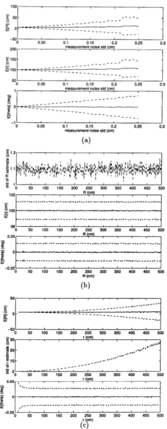
?Jeanwhile, the raw dat a was used at eachfiltering. T he expected value and standard deviations of these estimates were computed over the same 1000 realizations. In Table 1, experimental results for three different targets are displayed, which represent point, cylidrical and planar targets. In Figures 5 and 6. re- sults of a Monte Carlo study with 1000 realizations over a wider parameter range are illustrated. In ob- taining these results, the attenuation of the signal am- plitude was not considered to isolate the effect of the system configuration. In these results, whenever other parameters are varied, f? and q5 were kept constant at 0”. When
Q
and $ were varied, their maximum val- ues were limited t o k15’ since this is the approximate beamwidth of the mainlobe of the Polaroid transducer. Similarly, r was set to 100 cm, R = 5 cm and d = 1.5 cm unless where they were varied. In Figure 5 (a), the effect of increasing the standard deviation of the mea- surement noise standard deviation is illustrated. The solid lines indicate the mean values and the dashed lines correspond t o the one standard deviation inter- val around the mean. As expected, increasing the mea- surement noise increases the standard deviations of the estimated parameters. In Figure 5 (b) and (c) the ef- fect of varying R and r is seen on the accuracy of the other parameters. Varying the radius of the target does not seem to affect positional accuracy. The re-sults for E [ $ ] are almost identical to E[B], hence, they were not included here for brevity.
In Figure 6 (a), the results for varying 8 are given. Increasing 6’ increases the estimation error on 0 but does not affect the accuracy of the remaining param- eters since the attenuation in the signal amplitude is not considered. Same is true for
9,
and again, the results are not included here for brevity. In Figure 6 (b), the effect of varying d is illustrated. Increasing the transducer separation provides better resolution ofthe target parameters and reduces the standard devi- ation of the estimated parameters. If the target radius is much smaller compared to transducer separation, some of the sensors will not be able t o receive an echo from the target, setting an upper bound on d .
6
Conclusion
A sensing device capable of estimating the location and radius of curvature of spherical and cylindrical tar- gets has been described. Analytical results are verified by simulations and real data from cylindrical targets. Typical accuracies are less than 0.5 cm in curvature and range, and less than 1’ in angle. The two lim- its of interest are the point (3-D) or line (2-D) target and the planar target. T he next stage of this work is to track cylindrical targets in azimuth. A future more in-
telligent sensor could also have the capability to track in elevation to add more flexibility to the application.
References
R. Kuc “Three-dimensional tracking using qual- itative bionic sonar,” Robotics and Autonomous Systems, vol. 11, pp. 213-219, 1993.
M. L. Hong and L. Kleeman “Analysis of ultrasonic differentiation of three-dimensional corners, edges and planes,” in Proceedings IEEE International Conference on Robotics and Automation, pp. 580- 584, Nice, France, May 12-14, 1992.
L. Kleeman and H. Akbarally “A sonar sensor for accurate 3d target localization and classification,” in Proceedings IEEE International Conference on Robotics and Automation, pp. xxx-xxx, Nagoya, Japan, May 21-27, 1995.
H. Peremans, K. Audenaert and J . M. Van Camp- enhout “A high-resolution sensor based on tri-
aural perception,” IEEE Transactions on Robotics and Automation, vol. 9, pp. 36-48, February 1993. A. M. Sabatini “Statistical estimation algorithms for ultrasonic detection of surface features,” in Proceedings IEEE/RSJ International Conference on Intelligent Robots and Systems, pp. 1845-1852, Munich, Germany, September 12-16, 1994. B . Barshan and 0. Arikan “Performance analysis
of two linear array processing algorithms for point- obstacle localization,” in Proceedings SPIE Signal and Data Processing of Small Targets, pp. xxy-
xxx, San Diego, CA, July 11-13, 1995.
J . J . Leonard and H. F. Durrant-Whyte “Mobile robot localization by tracking geometric beacons,” IEEE Transactions on Robotics and Automation,
0. Bozma and R. Kuc “Characterizing pulses reflected from rough surfaces using ultrasound,” Journal of the Acoustical Society of America, vol. 89, pp. 2519-2531, June 1991.
Y. Bar-Shalom and T. E. Fortmann. Tracking and Data Association. Academic Press, New York, NY, 1988.
I 0.05 0.1 0.15 0.2 0.25 0.3 -501 measurement noise std (cm)
-
m :lo- g 2 0 - a= ~~ I 0.05 0.1 0.15 0.2 0.25 0.3 50' 1 , measurement noise std (cm).n'd
,,d.*.U_.
,-- ,v.,.."
- - - * - I 0.05 0.1 0.15 0.2 0.25 0.3 -1 I measurement noise std (cm) (a)-
P ' ts I 150 200 250 300 350 400 450 l o 2 0~'1
, ~ R(fm) , , , , . ,'j"
.-*.-.*....
*.---..,...-a...,,
"^.
..-
,.,,
,...6 .I ..l..r,.,.".. ..I..-,-
E ts g100 ~ ...,-,,-
-.--.
c.-.-.,-...,,.,,.
I.,.-,-,-..,,..-...,.
a*-..-* r._.-_..
,.-_
....
.Y.*...,
,. ...,.-.
" ,,.-..-
_"\....
,..>-.- o -. '-
,~-rr,,r^-.-.-,.-\-.-.
-,..a,-,".-",.,"*-,,..,.-..,
~..-.-,-,
-.-
I 0 50 100 150 200 250 300 350 400 450 500 98'
-0.05l I 0 50 100 150 200 250 300 350 400 450 500 R (cm) (b)-
_-_
--
- * -_ _ _ _ - - - -
'
'l! 50-
lA0 l;O 200 &I3 W 3kOdo
4 0
1 0_---_-_--.-__
4 3.5 - > - - - - . ._-,.--.
^ * \ _ _ _ < _ _ _ - __ _ _
5 10 15 theta (deg) --I I - - - _ _ _ _ _ _ _ _ _ _ _ _ _ _ _ _- -
-..-
it
2
_
_ _ _ _ _ _ _ _ _ _ _ - _ _ _ _ _ - - - L I 5 10 15 20 25 30 -0.2'Figure 6: Results showing the variation of mean and standard deviation of estimated parameters with 0 and