, VOL. , NO. , –
https://doi.org/./..
Experimental Thermal Performance Characterization of Flat Grooved Heat Pipes
Hossein Alijania, Barbaros Çetina, Yi ˘git Akku¸sb, and Zafer DursunkayacaMechanical Engineering Department, ˙I. D. Bilkent University, Ankara, Turkey;bASELSAN A.¸S., Yenimahalle, Ankara, Turkey;cDepartment of Mechanical Engineering, Middle East Technical University, Ankara, Turkey
ABSTRACT
The thermal characterization of aluminum flat grooved heat pipes is performed experimentally for different groove dimensions. Three heat pipes with groove widths of 0.2 mm, 0.4 mm, and 1.5 mm are used in the experiments. The effect of the amount of the working fluid is extensively studied for each groove width. The results reveal that, although all three succeed in dissipating the heat input through the phase change of the working fluid by continuous evaporation and condensation, the effectiveness of the heat transfer increases with reduced groove width. Furthermore, it is observed that there exists an optimum operating point, where the temperature difference between the heating and cooling sections is at a minimum, and the magnitude of this temperature difference is a strong function of the groove width. To the best of the authors’ knowledge, the combined effects of groove dimensions and the amount of the working fluid, from fully flooded to dry, is reported for the first time for aluminum flat grooved heat pipes.
Introduction
Heat pipes are passive heat removal devices and they are used in various terrestrial and space applications. They can transfer large amounts of heat from a heat source to a heat sink with small temperature gradients. This makes them a device of choice in applications where formation of hot spots is undesirable. The operation of a heat pipe is initiated by the vaporization of liquid-phase working fluid in the evaporator section, where heat is transferred from an external source. The vapor formed flows to the condenser section, where it condenses by transferring latent heat to the heat sink. The condensate flows back to the evaporator section, in most applications by the capillary effect.
Depending on the application area and available space, heat pipes can be present in various shapes, sizes and con-figurations including two-phase-closed thermosyphons, capillary-driven heat pipes, annular heat pipes, vapor chambers, rotating heat pipes, gas-loaded heat pipes, loop heat pipes, capillary pumped loop heat pipes, pul-sating heat pipes, and micro and miniature heat pipes [1]. In particular, capillary-driven heat pipes employ capillary effect by a wick structure to move the liquid-phase work-ing fluid back to the evaporator section. Wick structures may be present in various forms such as porous struc-tures, axial grooves, mesh-type strucstruc-tures, non-circular
CONTACT Assistant Professor Dr. Barbaros Çetin [email protected];[email protected] Mechanical Engineering Department, Bilkent University, Ankara, Turkey.
Color versions of one or more of the figures in this paper can be found online atwww.tandfonline.com/uhte.
micro-channels whose sharp-angled corners work as liquid arteries, or sometimes a combination of them [2]–[5]. Capillary-driven heat pipes are widely utilized in commercial and aerospace applications [1] due to their ability of working against or in the absence of gravity.
Numerical and experimental investigations on heat pipes have started in the mid-1960’s with the pioneering work of Grover et al. [6]. Heat pipes with various config-urations have been studied in the literature. Heat pipes utilizing grooved wick structures are of particular interest, due to the relative ease of developing analytical models and numerical solutions to estimate their performance. Various groove geometries have been studied, such as fan-shaped [7], circular [8], trapezoidal [8], [9], [11], and [12], triangular [13] and rectangular [8], [11], [14]–[22] cross-sections. Copper [7], [10], [11], [13]–[18], [22] and aluminum [9], [20], and [21] were the most common base materials used in the experimental studies. In addition to water, acetone, methanol, and n-pentane, which are all compatible with copper, some special solutions [22] and nano-fluids [16], [17] have been used in previous studies to investigate the effect of the working fluid on the thermal performance of copper heat pipes.
Considering the material of heat pipes, aluminum alloys are preferable to copper ones due to their lower cost, lightweight, and relative ease of machining. They
are widely applied in aerospace applications and low temperature environments. Due to the fact that alu-minum is incompatible with water—which is a desirable working fluid for many heat pipe applications—working fluids such as ammonia, acetone and ethane are used in aluminum heat pipes [23]. Despite the significance of aluminum as a heat pipe material, the number of the studies on aluminum grooved heat pipes is limited in the literature. In one recent study, the effects of anodized surface, filling ratio, inclination angle and heat input on thermal performance of an axially grooved tubular aluminum heat pipe with grooves of width 0.8 mm were experimentally investigated for a heat flux range of 0.4– 3.4 W/cm2, and concluded that anodized surface has
better heat transfer characteristics with shorter response time [20]. In another recent work, the effect of the shape of nanoparticles in acetone-based Al2O3 nano-fluids on
the thermal resistance of an aluminum flat-plate heat pipe is reported for a heat flux range of 0.20–0.73 W/cm2[21]. Present study
In the present experimental study, aluminum-grooved flat plate heat pipes charged with isopropyl alcohol (IPA) are thermally characterized. Rectangular grooves are machined in a pre-machined recess on the aluminum plate, and the system is confined with a transparent cover to enable instant visualization during heat pipe opera-tion. During experiments, three different groove widths, 0.2 mm, 0.4 mm, and 1.5 mm, are used and the influence of the amount of the working fluid is extensively studied in each experiment. In addition to the usage of IPA as the working fluid, the investigation of the effect of groove size on the thermal performance of aluminum flat plate heat pipes is one of the original aspects of the current research. Moreover, the unique contribution of the present study is that the combined effects of groove dimensions and amount of the working fluid, from fully flooded grooves to dry grooves, is reported in a single study.
Materials and methods Heat pipe assembly
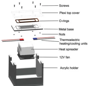
Figure 1shows the disassembled components of the heat pipe assembly which consists of an acrylic (plexiglas) top-plate, two o-rings, a metal base, thermoelectric heat-ing and coolheat-ing units, a fan-integrated heat spreader and the acrylic holder. The metal base has two rectangular grooves for the o-rings and flat grooves operating as heat pipe channels. The top cover is made of a transpar-ent material to enable the visualization of evaporation and condensation as well as recording the amount of the working fluid, and location and extent of probable
Figure .Heat pipe assembly.
dryout. The two o-rings suitable for vacuum applications are used for sealing. Six screws are placed to assemble the acrylic top plate and the metal base as well as fixing the position of the metal base on the micro-machining center. Thermoelectric cooling and heating units are in contact with the metal base on the bottom surface. In order to cool the hot surface of the thermoelectric cooling unit, a heat spreader integrated with a 12 V fan is used. The metal base sits on an acrylic holder, which carries the heat pipe and the fan-integrated heat spreader.
Fabrication of the metal base
Aluminum is selected as the base material due to its high thermal conductivity, ease of machining and low cost. Rectangular grooves are used as the wick struc-ture of the heat pipes which drive the liquid flow with capillary action. The groove density (i.e., number of grooves per unit width) is an important parameter on the thermal performance of a heat pipe. In this work, three sample heat pipes with different groove densities are investigated.
The fabrication of the metal base starts with the fab-rication of two rectangular o-ring grooves followed by the fabrication of a rectangular recess (78 mm × 23 mm) which is 2.5 mm below the top surface using conventional CNC-machining. This rectangular recess is the base for the fabrication of the grooves and acts as a space for vapor flow. At the bottom side of the metal base, small rectangular holes with a depth of 0.4 mm are machined to attach the thermocouples to the desired locations. The location of these holes are shown in Figure 2 and the dimensions of these samples are given inTable 1. The flat grooves are fabricated by a three-axis micro-machining center (PROINO Z3X Micro Maker) with ±5µm accu-racy. The fabrication of flat grooves consists of three
Figure .Top, bottom and mid cross-sectional views of the heat pipe assembly and the location of thermocouples (all dimensions are in mm).
major steps. Initially, the top surface of the rectangular recess is machined (with a 1.2 mm cutting tool, feed rate of 2.5 mm/min, and rotational speed of 25, 000 rpm) to enable the precise control of the depth of the grooves. Next, the grooves are machined by performing a fine machining with the following parameters:
!
A101: 0.2 mm tool, 1.0 mm/min feed rate,30, 000 rpm rotational speed
!
A102: 0.4 mm tool, 1.0 mm/min feed rate,30, 000 rpm rotational speed
!
A103: 1.2 mm tool, 2.5 mm/min feed rate,25, 000 rpm rotational speed
In the final step, a soft surface polishing is applied on the entire piece to remove the machining burr at the edge of the grooves. Following the fabrication, the sample is ultrasonically cleaned to ensure the removal of any residual debris remaining in the grooves. Finally, the sample is washed by soap and isopropyl alcohol, rinsed with deionized water and blow-dried. Five T-type Table .Dimensions and groove density of the heat pipes.
Sample groovesNo. of Groove width W [mm] Groove height H [mm] Fin widthF [mm] Groove density No. of grooves/mm width A . . . . A . . . . A . . . .
thermocouples (with an uncertainty of ±0.2◦C) are
embedded into the metal base at the centerline for tem-perature measurements. An additional thermocouple is placed at the midpoint of the plexiglas top cover. The loca-tions of the thermocouples together with the thermoelec-tric heating/cooling units are illustrated inFigure 2. The fabricated pieces are shown inFigure 3. The groove pro-files are also investigated with a 3D Laser Scanning Confo-cal Microscope (VK-X100, KEYENCE Corporation). The microscope image of the groove profiles are also provided in the figure. The surface roughness of the bottom surface of the grooves and the fin top surfaces are measured using the microscope at different locations. The average surface roughness of the bottom surface is found to be 0.32µm, 0.23µm, and 0.28µm for 0.2 mm, 0.4 mm, and 1.5 mm
grooves, respectively. The surface roughness of the fin top surfaces are obtained as 0.29µm, 0.31µm, and 0.35µm
for the same samples, respectively. It is evident from the measurements that there is no significant variation on the machining quality of the pieces which eliminates surface roughness effect on the comparison between the different groove widths.
Heating and cooling units
Thermoelectric devices capable of converting electricity into thermal energy or vice versa are a convenient solution for local heating/cooling applications. The thermoelectric modules used in this study are of type TEC1-03106T125 with dimensions of 2 cm × 2 cm × 4 mm. The module whose hot/cold side is in contact with the heat pipe acts as the heat source/sink. Thermal paste is applied on con-tact surfaces of the modules to reduce thermal concon-tact resistance. The heat source and heat sink positions are such that they are placed exactly under the grooves array, as shown inFigure 2. It should be noted that the input current to both heat source and heat sink is kept con-stant during all experiments for all samples. Therefore, the heat input and output of all of heat pipes during all experiments are intended to be equal.
Working fluid
The compatibility of the working fluid with the heat pipe material, its thermal and wettability properties, and desired operating temperature range of the heat pipe are crucial in the selection of the working fluid in heat pipes [22], [24]. IPA is compatible with aluminum whereas water is not. Hence, IPA was selected as the working fluid in this study.Table 2shows the relevant physical and ther-mal properties of IPA [25].
Experimental set-up
The experimental set-up is built by integrating the vacuum unit, pressure sensors, thermocouples, data
Figure .Fabricated metal pieces and the groove profiles. acquisition system and other auxiliary units such as power supplies and computers to the heat pipe assem-bly. One two-channel power supply is used to run the thermoelectric heating and cooling units, another power supply is used to drive the fan. The photograph of the experimental set-up is given in Figure 4. In order to ensure the removal of all of the air from the system, all the components (valves, connectors, etc.) used are gas tight. The working fluid is also degassed for at least 15 minutes prior to charging the heat pipe for the removal of any possibly dissolved air.Figure 5depicts the schematic of the heat pipe connected to the vacuum pump. The con-nection of the heat pipe to the vacuum pump is made by using some ball valves, T-junctions, and flexible pipes. To be assured of removal of any air inside the connections, pressure is monitored in two different locations, one close to the vacuum pump and the other right after the heat pipe.
Experimental method
The input powers given to the thermoelectric heating and cooling units are recorded during the experiments. In order to minimize the heat transferred to the ambient, Table .Physical and thermal properties of IPA [].
Property Value Unit
Thermal conductivity (25◦C) . W/m·K Surface tension (25◦C) . mN/m
Viscosity (25◦C) . mPa·s
Boiling point . ◦C
Heat of vaporization (at boiling point) kJ/kg
the power inputs to the thermoelectric units are adjusted in such a way that the temperature measured at the mid-point of the top plexiglas cover is equal to the ambient temperature.
Each experiment is completed in a single run during which the amount of the working fluid is changed from fully flooded (i.e., fully flooded case) volumes to dry heat pipe. Figure 6 shows one sample run of 0.2 mm groove heat pipe. Initially all grooves and volumes are fully flooded with IPA, and the heating and cooling units are operating. Every sudden change corresponds to the removal of some IPA with the vacuum pump, to which the system responds with changing temperatures. Once the steady operation is reached more IPA is removed, moving to another operating point. After each IPA removal, the IPA is collected on the condenser side of the heat pipe by tilting, and the extent of the liquid IPA in the grooves is measured under the effect of gravity (Figure 7). This procedure is repeated until all IPA is removed and the unit transfers heat only by conduction in aluminum. After completion of the run, the optimum operating point is found, the point which corresponds to the minimum temperature difference between the heater and the cooler. Strictly speaking, this optimum is not a proper optimum operating point, since IPA removal is performed in discrete steps, which are course, thus rendering the possibility that the true optimum point may be missed between two consecutive steps. Nevertheless, the results are judged to be sufficiently close and further improvements are planned for future studies.
Figure .Experimental set-up and close-up view of the heat pipe.
Figure .Schematic drawing of the assembly of the heat pipe and vacuum unit connections. (Note: the figure is not drawn to scale.)
Results and discussion
Tests are conducted for heat pipes with 0.2 mm (A101), 0.4 mm (A102), and 1.5 mm (A103) groove widths. The cooling unit is operated around its maximum power (approximately 6 W), and the power of the heating unit is adjusted to keep the temperature at the midpoint of the top plexiglas cover around ambient. Although the input powers are recorded, the heat addition and removal through the evaporator and condenser sections require
Figure .Typical transient temperature data for a single run of heat pipe A.
the value of the coefficient of performance (COP) of thermoelectric units. Typically, COP of thermoelectric units is a function of many parameters such as applied current, temperature of the hot and cold surfaces, and temperature difference between the hot and cold sides. Moreover, COP data also show a variation depend-ing on the manufacturer. A reliable COP data for the
Figure .Orientation of the heat pipes during the measurement of liquid extent.
15 20 25 30 0 1 2 3 4 5 6 7 Te m pe ra tu re [° C] Axial position [cm] 15 20 25 30 0 1 2 3 4 5 6 7 Te m pe ra tu re [° C ] Axial position [cm] 15 20 25 30 0 1 2 3 4 5 6 7 Te m pe ra tu re [° C] Axial position [cm] (a) Simulation Fully-flooded: Dry: Experiment Simulation Experiment (b) (c)
Heat source Heat sink Heat source Heat sink
Heat source Heat sink
Figure .Simulated and measured temperatures at the bottom of the heat pipes: (a) A, (b) A, (c) A. thermoelectric units used in this study, however, is not
available. Therefore, a simple computational model based on heat conduction alone (kAl= 140 W/m · K) is
devel-oped using a finite element-based commercial software, COMSOL Multi-physics, to quantify the heat input in the experiments. One half of the heat pipe is simulated due to symmetry. Insulated boundary conditions are applied on the side and bottom surfaces, and natural convection is assumed at the top surface with convective heat transfer coefficient of h = 5 W/m2· K. Constant temperature
values are assigned on the surfaces where the thermoelec-tric units are located. The model is used to study the two extreme cases of working fluid amount; fully flooded and dry, and exercised to match the experimentally recorded plexiglas and aluminum temperatures at a total of 6 points. Through this model, the heat flux for the experi-ments is estimated to be in the range of 1.40–1.80W/cm2.
The comparison of the experimental data and the sim-ulation results can be seen in Figure 8. Although the same constant electrical power is supplied to thermoelec-tric units, this variation in heat flux is attributed to the dependence of COP value on operating conditions.
For each heat pipe, five different IPA amounts are used from fully flooded to dry.Figure 9shows the temperature differences between temperatures measured at locations
described inFigure 2(T1 through T5) and the plexiglas
temperature (T6) which is kept approximately equal to
the ambient temperature. This is done because during the experiments both the ambient temperature, which is not controlled, and hence the plexiglas temperature varied. This referencing eliminates the erroneous interpretation of the temperature curves for different IPA extents. In the current study, filling ratio is defined as the ratio of the total volume of the working fluid inside the heat pipe to the total volume of the grooves (Vfluid/Vgroove), and
the estimated ranges of filling ratios corresponding to different cases are tabulated in Table 3. Due to inaccuracies in the measurement of the liquid extent, the estimated range of optimum operating points is large, especially for higher groove densities. The temperature variations along the heat pipes are similar for the fully flooded and dry cases, and display a linear behavior for the fully flooded and dry cases. This is expected since the heat transfer is due to conduction only in the absence of phase change. In the fully flooded case, there is a possi-bility of heat transfer due to conduction and convection in the liquid. Both of these, however, are found to be very small; conduction due to the extremely small thermal conductivity of IPA compared to that of aluminum, and convection due to very small velocities in the liquid. Since
-5 -4 -3 -2 -1 0 1 2 3 4 5 0 1 2 3 4 5 6 7 T-T pl ex i [°C] Axial position [cm] -5 -4 -3 -2 -1 0 1 2 3 4 5 0 1 2 3 4 5 6 7 T-Tplex i [°C] Axial position [cm] -5 -4 -3 -2 -1 0 1 2 3 4 5 0 1 2 3 4 5 6 7 T-Tplex i [°C] Axial position [cm] (c) G1-1500 (a) G1-200 (b) G1-400 Heat sink Heat source Heat sink Heat source Heat sink Heat source
Fully-flooded Extent: 3cm Extent: 2cm
Optimum Partial dryout Dry
Extent: 1cm Extent: 0.5cm
Figure .Temperature differences between thermocouples (T1through T5) and the plexiglas temperature (T6): (a) A, (b) A, (c) A. the heat transfer in the fully flooded case is through
con-duction in both the base metal and liquid, the temperature differences measured in the close proximity of the heater and the cooler are expected to be slightly lower compared to the dry-case, where the heat transfer is in the base metal only. InFigures 9aand9c, however, the temperature dif-ference on the heater side of the dry case is lower than the fully flooded case. The same trend is also seen inFigure 9a
in the proximity of the cooler side as well. This unex-pected behavior can be attributed to the accuracy of the calculated temperature reading difference, which is esti-mated to be (±0.2◦C). With the removal of IPA, the phase
change complements conduction and the temperature curves flatten and all temperatures approach the ambient temperature. This is characteristic of heat pipes, where the temperature difference between the high temperature
and low temperature reservoirs are small, and these temperatures remain close to ambient temperature for low heat flux values. At the optimum operating point, phase change is dominant, and the slope of the tem-perature curve is at its minimum, showing that heat conduction in the metal base is at a minimum. Once the temperature difference between the heater and cooler reaches a minimum at the optimum operating point, any additional removal of IPA forces the system to partial dryout and an increase in the temperature differences. The optimum point is achieved with a small quantity of working fluid, and therefore is very close to the dry oper-ating condition. Although the estimates of filling ratios cover a wide range, it can be concluded that the filling ratio at the optimum point decreases with lower groove density.
Table .Estimated range of filling ratios (Vfluid/Vgroove) corresponding to different cases.
A A A
Case Filling ratio Case Filling ratio Case Filling ratio
Fully-flooded . Fully-flooded . Fully-flooded .
Extent: cm .–. Extent: cm .–. Extent: cm .–.
Extent: cm .–. Extent: cm .–. Extent: . cm .–.
Optimum .–. Optimum .–. Optimum .–.
Partial dryout — Partial dryout — Partial dryout .–.
0 1 2 3 4 5 6 7 8 9 Fully-flooded 2cm Dry Δ T [° C] 0 1 2 3 4 5 6 7 8 9
Fully-flooded 0.5cm Partial Dryout
Δ
T
[°
C]
(a) (b)
A101 A102 A103
Fully-flooded 3 cm 2 cm Optimum Dry floodedFully- 1 cm 0.5 cm OptimumDryoutPartial Dry
Figure .Temperature difference between the heater and cooler sections (T1− T5): (a) A and A, (b) A. Since the heat pipes make use of phase change heat
transfer enabling lower temperature differences and lower peak temperatures compared to conventional counterparts, and also due to the strict peak tempera-ture requirements of current electronic devices, in the current study the measure of the thermal performance of a heat pipe is the temperature difference between the heater and cooler sections for a given heat load, and the heat pipe operating with the minimum tempera-ture difference is defined to be at the optimum point of operation. The temperature difference between the heater and cooler sections (T1− T5) is given inFigure 10
for different operating conditions. For A101, the tem-perature difference between the heater and cooler is 6.9◦C (±0.2◦C) for the fully flooded case, dropping
grad-ually to 0.9◦C (±0.2◦C) for the optimum and increasing
to 6.5◦C (±0.2◦C) for the dry case. This shows that with
the removal of IPA the system operates like a heat pipe, eventually reverting back to conduction only for the dry case. A similar performance is observed for A102 and A103 where the temperature differences between the heating and cooling units are 8.5◦C (±0.2◦C) and
7.2◦C (±0.2◦C) for the fully flooded case, and reaching a
minimum of 1.5◦C (±0.2◦C) and 1.9◦C (±0.2◦C) at the
optimum and eventually reaching 8.3◦C (±0.2◦C)
and 7.2◦C (±0.2◦C) for the dry operation,
respectively. The operating characteristics of different groove widths are also apparent in the results. The major-ity of evaporation occurs near contact line within the groove; therefore increasing the number of grooves (i.e., groove density) enhances phase change heat transfer to the fluid [26]. A major fraction of the heat input is transferred through phase change rather than conduc-tion through the heat pipe bulk material, resulting in a considerable reduction in the temperature difference between the heat source and sink. A difference in groove width and the corresponding fin width also changes the conduction in the fin cross-section; this effect, how-ever, is believed to be minor compared to the effect of the
increase in length of the contact line. The temperature difference between the heater and cooler sides can be considered as a measure of the effectiveness of a heat pipe. A101 with the highest groove density (i.e., the smallest groove size) has the best performance with a minimum temperature difference of 0.9◦C (±0.2◦C).
Another observation is the existence of a partial dryout in the case of A103, which is not seen in the other two samples. In A101 and A102, the amount of IPA left in the grooves is excessively small and an attempt to remove additional IPA resulted in a total removal of all remaining IPA, bringing the system to dry operating condition. In case of A103, however, there is substantially more IPA left inside the grooves compared to A101 and A102 at the optimum operating point; therefore it is possible to remove more IPA from the system without rendering the grooves entirely dry. This enables the operation of the system with partial dryout conditions, where some of the grooves are void of liquid IPA in the vicinity of the heater unit.
Concluding remarks
Thermal performance of three flat grooved heat pipes is investigated experimentally for different groove dimen-sions. The effect of the amount of the working fluid is studied for each groove width. It is observed that the effectiveness of the heat transfer increases with reduced groove width (i.e., increased groove density) due to increased contact line and improved evaporation. More-over, there exists an optimum operating point, where the temperature difference between the heating and cooling sections is at a minimum, and the magnitude of this temperature difference is a strong function of the groove width. The heat pipe with 0.2 mm grooves has the best thermal performance, removing the same amount of heat with the minimum temperature difference between the heater and cooler for the input heat flux range considered. In the fully flooded and dry operating conditions, the
temperature difference between the heater and cooler is about 6.9◦C (±0.2◦C) dropping to 0.9◦C (±0.2◦C) with
IPA removal for this heat pipe.
The optimum operating point of grooved heat pipes is a function of numerous parameters, and in the cur-rent study only the effect of filling ratio and groove den-sity are studied. In order to develop a predictive analysis methodology, the influence of other design and operating parameters, including but not limited to heat load, extent of the adiabatic region and the vapor temperature need to be studied. Further research addressing these effects should concentrate analysis and experimentation for a better understanding of underlying physics.
In the current study, the actual amount of heat trans-ferred to the heat pipe cannot be measured precisely because of the heating and cooling with thermoelec-tric units. Therefore, all experiments are conducted at a constant power input to the thermoelectric units. The amount of IPA in the system, which directly affects the performance, is measured approximately by measuring the extent of liquid IPA in the grooves. Furthermore, the removal of IPA from the grooves after the optimum point is reached, is very sudden due to the excessively small amount of IPA left in the system at this point. These short-comings will be addressed in the continuation of the cur-rent study to better understand and quantify aluminum flat grooved heat pipe thermal performance as a func-tion of input heat flux and groove density. Future research efforts will also concentrate on the development of a com-putational model to predict the effect of three dimension-ality on the thermal performance of an aluminum flat grooved heat pipe.
Nomenclature
COP coefficient of performance of thermoelectric units
F fin width, mm H groove depth, mm
h convective heat transfer coefficient, W/m2· K
IPA isopropyl alcohol
k thermal conductivity, W/m · K T temperature,◦C
TC thermocouple
Vfluid total volume of the working fluid inside of the
heat pipes, cc
Vgroove total volume of the grooves, cc
W groove width, mm
Subscript
Al aluminum
Acknowledgments
Authors would like to thank Mr. Fatih Altunel for his guidance during the machining of the metal pieces.
Funding
This study is financially supported by the Turkish Scientific and Technical Research Council, under grant No. 213M351.
Notes on contributors
Hossein Alijani is an M.Sc. student in the Mechanical Engi-neering Department at Bilkent University, Ankara, Turkey. He received his B.Sc. in petroleum engineering from Sharif Uni-versity of Technology, Tehran, Iran. He is currently working on thermal performance characteri-zation of flat grooved heat pipes.
Barbaros Çetinis a faculty mem-ber in the Mechanical Engi-neering Department at Bilkent University, Ankara, Turkey. He received his Ph.D. in the Depart-ment of Mechanical Engineer-ing at Vanderbilt University. His research focuses on the elec-trokinetic transport and particle manipulation in lab-on-a-chip devices for biomedical applica-tions, and modeling and experi-mentation of grooved heat pipes. He has co-authored more than 100 refereed journal, conference publications, and encyclopedia entries. He has recently received Bilkent University Distinguished Teaching Award (2015) in recognition of excellence in teaching.
Yi˘git Akku¸sis a senior engineer in ASELSAN A.¸S. He received his B.Sc. and minor degrees from the Mechanical Engineering and Materials and Metallurgical Engineering Departments of Middle East Technical Univer-sity, Ankara, Turkey, in 2009, respectively. He obtained his Ph.D. degree from the Mechan-ical Engineering Department of Middle East Technical University in 2015. His research interests include the modeling and experimentation of heat pipes, and modeling of droplet and thin film evaporation.
Zafer Dursunkayais a professor at the Mechanical Engineering Department of Middle East Technical University, Ankara, Turkey, where he obtained his B.Sc. in 1981. He received his M.Sc. and Ph.D. degrees from the Mechanical Engineering Department of Illinois Institute of Technology, USA, in 1984 and 1988, respectively. Prior to joining Middle East Technical University, he worked in Ricardo between 1989 and 1994 as a senior engineer. His research interests include micro-grooved heat pipes, moving bound-ary/phase change problems, piston lubrication and its design, oil consumption in internal combustion engines, hydrody-namic lubrication, journal bearings, piston ring dyhydrody-namics, ring lubrication, and fluid instability.
References
[1] A. Faghri, “Review and advances in heat pipe science and technology,” J. Heat Transfer, vol. 134, pp. 123001– 123001-18,2012.
[2] P. Stephan and C. Brandt, “Advanced capillary structures for high performance heat pipes,” Heat Transfer Eng., vol. 25, no. 3, pp. 78–85,2004.
[3] L. L. Jiang, T. Yong, Z. Wei, L. Z. Jiang, and L. S. Lu, “Fab-rication of flatten grooved-sintered wick heat pipe,” Trans. Nonferrous Metals Soc. China, vol. 23, no. 9, pp. 2714– 2725,2013.
[4] X. Li, M. Li, R. Wu, Y. Wan, and T. Cheng, “Forming method of micro heat pipe with compound structure of sintered wick on grooved substrate,” Heat Mass Transfer, vol. 52, no. 3, pp. 581–593,2016.
[5] Y. Li, Z. Li, C. Chen, Y. Yan, Z. Zeng, and B. Li, “Ther-mal responses of heat pipes with different wick structures under variable centrifugal accelerations,” Appl. Thermal Eng., vol. 96, pp. 352–363,2016.
[6] G. M. Grover, T. P. Cotter, and G. F. Erikson, “Structure of very high thermal conductance,” J. Appl. Phys., vol. 35, no. 6, pp. 1990–1991,1964.
[7] H. T. Lim, S. H. Kim, H. D. Im, K. H. Oh, and S. H. Jeong, “Fabrication and evaluation of a copper flat micro heat pipe working under adverse-gravity orientation,” J. Micromech. Microeng., vol. 18, no. 10, pp. 105013–105013-8,2008.
[8] R. Schlitt, “Performance characteristics of recently devel-oped high-performance heat pipes,” Heat Transfer Eng., vol. 16, no. 1, pp. 44–52,1995.
[9] A. R. Anand, A. J. Vedamurthy, S. R. Chikkala, S. Kumar, D. Kumar, and P. P. Gupta, “Analytical and experimental investigations on axially grooved aluminum-ethane heat pipe,” Heat Transfer Eng., vol. 29, no. 4, pp.xbrk 410–416,
2008.
[10] S. Lips, F. Lefèvre, and J. Bonjour, “Nucleate boiling in a flat grooved heat pipe,” Int. J. Thermal Sci., vol. 48, no. 7, pp. 1273–1278,2009.
[11] R. Hopkins, A. Faghri, and D. Khrustalev, “Flat miniature heat pipes with micro capillary grooves,” J. Heat Transfer, vol. 121, no. 1, pp. 102–109,1999.
[12] A. J. Jiao, H. B. Ma, and J. K. Critser, “Evaporation heat transfer characteristics of a grooved heat pipe with micro-trapezoidal grooves,” Int. J. Heat Mass Transfer, vol. 50, no. 15, pp. 2905–2911,2007.
[13] X. Xu and V. P. Carey, “Film evaporation from a micro-grooved surface-An approximate heat trans-fer model and its comparison with experimental data,” J. Thermophys. Heat Transfer, vol. 4, no. 4, pp. 512–520,1990.
[14] D. Plesch, W. Bier, D. Seidel, and K. Schubert, “Minia-ture heat pipes for heat removal from microelectronic cir-cuits,” Meeting of the American Society of Mechanical Engineers, Atlanta, GA, Dec. 1–6,1991.
[15] Y. Cao, J. E. Beam, and B. Donovan, “Air-cooling system for metal oxide semiconductor controlled thyristors employing miniature heat pipes,” J. Ther-mophys. Heat Transfer, vol. 10, no. 3, pp. 484–489,
1996.
[16] X. F. Yang, Z. H. Liu, and J. Zhao, “Heat transfer per-formance of a horizontal micro-grooved heat pipe using CuO nanofluid,” J. Micromech. Microeng., vol. 18, no. 3, pp. 035038–035038-6,2008.
[17] Z. H. Liu and L. Lu, “Thermal performance of axially microgrooved heat pipe using carbon nanotube suspen-sions,” J. Thermophys. Heat Transfer, vol. 23, no. 1, pp. 170–175,2009.
[18] S. Lips, F. Lefèvre, and J. Bonjour, “Combined effects of the filling ratio and the vapour space thickness on the perfor-mance of a flat plate heat pipe,” Int. J. Heat Mass Transfer, vol. 53, no. 4, pp. 694–702,2010.
[19] T. Yousefi and M. Heidari, “Thermal performance enhancement of L-shaped microgrooved heat pipe con-taining water-based Al2O3 nanofluids,” Heat Transfer Eng., vol. 36, no. 5, pp. 462–470,2015.
[20] A. B. Solomon, A. M. Ram Kumar, K. Ramachandran, B. C. Pillai, C. Senthil Kumar, M. Sharifpur, and J. P. Meyer, “Characterisation of a grooved heat pipe with an anodised surface,” Heat Mass Transfer, vol. 53, no. 3, pp. 753–763,
2017.
[21] H. J. Kim, S. H. Lee, S. B. Kim, and S. P. Jang, “The effect of nanoparticle shape on the thermal resistance of a flat-plate heat pipe using acetone-based Al2O3 nanofluids,” Int. J. Heat Mass Transfer, vol. 92, pp. 572–577,2017.
[22] J. Supowit, T. Heflinger, M. Stubblebine, and I. Catton, “Designer fluid performance and inclination angle effects in a flat grooved heat pipe,” Appl. Thermal Eng., vol. 101, pp. 770–777,2016.
[23] X. Yang, Y. Y. Yan, and D. Mullen, “Recent devel-opments of lightweight, high performance heat pipes,” Appl. Thermal Eng., vol. 33, pp. 1–14,
2012.
[24] A. Faghri, “Heat pipes: Review, opportunities and chal-lenges,” Front. Heat Pipes, vol. 5, no. 1, pp. 1–48,2014. [25] W. M. Haynes, CRC Handbook of Chemistry and Physics,
96th ed. Boca Raton, FL: CRC Press/Taylor and Francis,
2016.
[26] Y. Akku¸s and Z. Dursunkaya, “A new approach to thin film evaporation modeling,” Int. J. Heat Mass Transfer, vol. 101, pp. 742–748,2016.