578 IEEE MICROWAVE AND WIRELESS COMPONENTS LETTERS, VOL. 23, NO. 11, NOVEMBER 2013
Novel Microstrip Fed Mechanically
Tunable Combline Cavity Filter
Sinan Kurudere and Vakur B. Ertürk
Abstract—A novel configuration for mechanically tunable combline bandpass filters is proposed, where the classical res-onating rod-tuning screw combination is replaced with a simple printed circuit-tuning screw combination. Moreover, because a printed circuit structure that uses metal vias forms the bottom part of the cavity, the coaxial type feeding and the coaxial to cavity matching of classical combline filters are also replaced with a microstrip feeding. Consequently, the proposed configuration provides smaller size, less weight, integration with other printed circuits and significant simplification in the fabrication process. A prototype filter is designed and fabricated for verification. The measured results are in good agreement with the simulation, and the filter exhibits very good harmonic suppression.
Index Terms—Harmonic suppression, tunable combline filters (TCFs).
I. INTRODUCTION
R
ECENT advances in wireless communication and radar applications demand high performance tunable filters that can meet the stringent requirements of the systems imposed on the filters, and to compensate undesired filter responses due to possible manufacturing tolerances [1], [2]. Therefore, var-ious tunable filter topologies have been reported [3], [4] in-cluding electronically and mechanically tunable combline fil-ters (MTCFs) [1]–[9], the latter still widely preferred owing to good filter performance, linearity, low loss, low cost and good spurious response. Electronically tunable combline filters can provide high tuning speeds and can be electrically small when realized in printed form [1], [5]. However, higher insertion loss (compared to their mechanically tunable counterparts), limited power handling capacity, and effetcs of intermodulation distor-tion produced by the varactor or other type of active device, as well as the requirement of an external biasing network, should be considered. On the other hand, low tuning speed, relatively bulky size and heavy weight (at low frequencies), integration with other printed circuits and manufacturing difficulties as-sociated with both the coaxial to cavity matching section and the small sized resonators (especially at high frequencies) ap-pear as the main problems of MTCFs. Therefore, several studies have been reported to address these problems using quasi-planarManuscript received June 19, 2013; revised July 23, 2013; accepted Au-gust 15, 2013. Date of publication September 23, 2013; date of current version November 04, 2013.
The authors are with the Department of Electrical and Electronics Engineering, Bilkent University, Ankara, 06800 Turkey (e-mail: [email protected]; [email protected]).
Color versions of one or more of the figures in this letter are available online at http://ieeexplore.ieee.org.
Digital Object Identifier 10.1109/LMWC.2013.2281432
realizations [6], and microelectromechanical systems (MEMS) technology [7], [8], as well as to improve their spurious perfor-mance [9].
In this letter we propose a novel microstrip fed mechanically tunable combline cavity bandpass filter. The proposed structure uses tuning screws, and a simple printed circuit as the bottom part of the cavity to replace the tuning screw-resonating rod combination of classical MTCFs. Therefore, the two ports of the filter use a simple 50 microstrip line as feeding, which is one of the main novelty of the proposed filter, resulting into easy in-tegration with printed devices. Consequently, the proposed filter is smaller in size, lighter in weight and easier to fabricate when compared with the classical MTCFs. A third order prototype bandpass filter with a center frequency of 5.25 GHz and a 17% 3 dB fractional bandwidth is designed and fabricated for verifi-cation. The fabricated filter has a center frequency tuning range of approximately 10%, and exhibits very good harmonic sup-pression.
II. FILTERDESIGN
The proposed symmetric filter is shown in Fig. 1 (3-D model in Fig. 1(a), side and top views in Fig. 1(b) and Fig. 1(c), respec-tively). The diameter and length of the stable part of each tuning screw are and , respectively, whereas their adjustable parts have a diameter of [see Fig. 1(b)]. Note that the tuning screws function as resonating rods as well and hence, they form the bulky part of the filter. The center to center distance between the tuning screws is , which mainly determines the band-width. The bottom part of the cavity is formed from a printed circuit whose layout is depicted in Fig. 1(c), part of which re-sembles to the resonators of a substrate integrated waveguide based coplanar waveguide fed combline filter proposed in [10]. In this configuration the filter is fed with a 50 microstrip line that has a length of (from the wall of the box), and is con-nected to a conducting annular ring whose outer and inner di-ameters are given by and , respectively. There is a grounded metal via with a diameter of at the center of the an-nular ring, and the diameter of the conducting part around this via is (same for both ports). The middle grounded metal via is (center-to-center from the first and third vias) away from the first and the third ones, has the same diameter; how-ever, the diameter of the conducting part around it is . Note that and affect the center frequency of the filter. Also note that each via is placed exactly under the corresponding tuning screw. The tuning of the filter is performed by the gaps between the tuning screws and the vias, and the gap length is for the first and third tuning screw-via combination whereas it is for the middle one. As the gap lengths are decreased the
KURUDERE AND ERTÜRK: NOVEL MICROSTRIP FED MECHANICALLY TUNABLE COMBLINE CAVITY FILTER 579
Fig. 1. Configuration of the proposed mechanically tunable bandpass filter. (a) 3-D view, (b) side View, (c) top view (tuning screws are hidden to show the printed circuit layout in detail).
resonance frequency moves towards the lower frequency side, and vice versa. As it can be understood, the number of tuning screw-via combinations determines the order of the filter. The most critical parameters for matching at the desired frequency are , and . Finally, mounting screws with 2 mm di-ameter are used in addition to epoxy to stabilize the substrate to the bottom of the box whose height and wall-to-wall width in the middle are shown with in Fig. 1(b) and in Fig. 1(c), respec-tively. The box dimensions are important since walls of the box affect the tuning screw performance by causing capacitive ef-fects. Note that wall-to-wall width of the box increases around the mounting screws. However, it does not affect the filter re-sponse. Hence, it can be kept as small as possible.
The equivalent circuit model of the proposed filter is shown in Fig. 2 with the element values corresponding to the center frequency of 5.25 GHz. The first [and the last ] ca-pacitor is feeding related and represents two capacitive effects, namely the capacitance between the grounded metal via and the conducting annular ring around it, and the capacitance between the tip of the tuning screw and the aforementioned conducting annular ring. The value of these equivalent capacitors increase when is decreased (and decrease when is increased). Each L-C pair represents the tuning screws and the grounded metal via combination. Because the filter is symmetric and pairs are identical. In all these three L-C pairs, again the values of the equivalent capacitors are related with the gap
Fig. 2. Equivalent circuit model of the proposed filter. TABLE I
DIMENSIONS OF THEFILTER
Fig. 3. Unloaded Q-factor of a single resonator.
Fig. 4. Photograph of the fabricated prototype filter.
lengths and in such a way that, an increase in decreases the values of both and , whereas an increase in de-creases the value of . Finally, the capacitive effect between the tuning screws is represented by the capacitors between the L-C pairs. Table I presents the dimensions of the filter for the center frequency of 5.25 GHz, as well as the and values for the tune-up and tune-down cases.
Using CST MWS and making use of [11], the unloaded Q-factor of a single resonator is calculated including dielectric and conductor losses and it is shown in Fig. 3. Based on the simulations, approximately 65% of the losses are due to con-ducting parts of the filter, and the remaining losses are due to dielectric parts.
III. FABRICATION ANDMEASUREMENT
Microstrip part of the filter is fabricated on Rogers TMM10i that has a thickness of 0.635 mm, and loss tangent 0.002 (at 10 GHz). The 50 microstrip line that feeds the filter
580 IEEE MICROWAVE AND WIRELESS COMPONENTS LETTERS, VOL. 23, NO. 11, NOVEMBER 2013
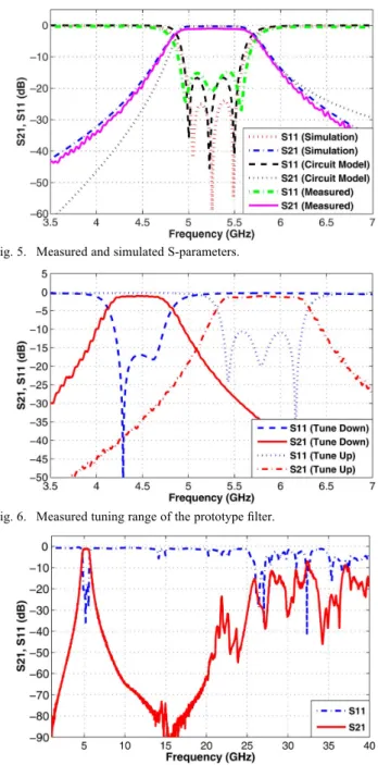
Fig. 5. Measured and simulated S-parameters.
Fig. 6. Measured tuning range of the prototype filter.
Fig. 7. Measured spurious performance of the prototype filter.
has a width of 0.559 mm. Mechanical parts are built with alu-minum and are plated with Ni and Au to prevent oxidation. Fig. 4 shows a photograph of the fabricated third order proto-type filter together with a view of its inner bottom part (i.e., the microstrip part of the filter) for the dimensions given in Table I. For this prototype, Fig. 5 shows the comparison of measured and simulated, as well as the circuit model simulated S-param-eter (i.e, and ), results. Good agreement is obtained in all results. However, the measured 1 dB insertion loss is higher than that of simulated, which is 0.3 dB (0.1 dB is due to the copper parts of the conductors (conducting parts of the feeding and metallic vias), 0.1 dB is due to the aluminum parts (box and the tuning screws), and dielectric losses form the remaining 0.1 dB). The 0.7 dB difference in the insertion loss can be at-tributed to the connector losses, as well as some unpredicted losses due to materials used to construct the prototype such as epoxy, gold plating of the box, etc. The tuning range of the filter
is investigated in Fig. 6, and the center frequency can be tuned approximately 10% for a return loss of 10 dB. Increasing the capacitances by decreasing and tunes the band to a lower frequency range, and decreasing the capacitances (by increasing and ) tunes to a higher frequency range. Besides, as seen in Fig. 6, the 3 dB fractional bandwidth of the filter is measured as 17% and it remains constant throughout the tuning range. On the other hand, if the absolute bandwidth of the filter is desired to be kept constant, more sophisticated coupling schemes are necessary. However, in that case an increase both in terms of re-turn losses due to matching problems, and of the insertion loss increment due to extra components and manufacturing issues, is expected. Therefore, this idea is abandoned for this filter. Fi-nally, the fabricated filter’s harmonic suppression is better than 50 dB up to 21 GHz as shown in Fig. 7. It should be noted that the SMA connectors used in the prototype degrade the perfor-mance of the filter above 18 GHz.
IV. CONCLUSION
A novel microstrip-fed mechanically tunable combline cavity bandpass filter configuration is presented. The bottom part of the cavity is a simple printed circuit that uses a microstrip line as a feeding, thus resulting into simpler fabrication and easy in-tegration with other printed devices. Besides, the printed cir-cuit-tuning screw combination provides smaller size and less weight especially at low frequencies. The proposed structure is verified with a fabricated prototype which exhibits very good harmonic suppression and good filtering properties.
REFERENCES
[1] M. S. Renedo, R. G. Garcia, J. I. Alonso, and C. B. Rodriguez, “Tunable combline filter with continuous control of center frequency and band-width,” IEEE Trans. Microw. Theory Tech., vol. 53, no. 1, pp. 191–199, Jan. 2005.
[2] F. Mira, J. Mateu, and C. Collado, “Mechanical tuning of substrate inte-grated waveguide resonators,” IEEE Microw. Wireless Compon. Lett., vol. 22, no. 9, pp. 447–449, Sep. 2012.
[3] I. C. Hunter, L. Billonet, B. Jarry, and P. Guillon, “Microwave filters-applications and technology,” IEEE Trans. Microw. Theory Tech., vol. 50, no. 3, pp. 794–805, Mar. 2002.
[4] G. Matthaei, E. M. T. Jones, and L. Young, Microwave Filters,
Impedance-Matching Networks, and Coupling Structures. Norwood,
MA: Artech House, 1980.
[5] G. T. Penalva, G. L. Risueno, and J. I. Alonso, “A simple method to design wide-band electronically tunable combline filters,” IEEE Trans.
Microw. Theory Tech., vol. 50, no. 1, pp. 172–177, Jan. 2002.
[6] W. T. Lo and C.-K. C. Tzuang, “K-band quasi-planar tapped combline filter and diplexer,” IEEE Trans. Microw. Theory Tech., vol. 41, no. 2, pp. 215–223, Feb. 1993.
[7] W. D. Yan and R. R. Mansour, “Tunable dielectric resonator bandpass filter with embedded MEMS tuning elements,” IEEE Trans. Microw.
Theory Tech., vol. 55, no. 1, pp. 154–160, Jan. 2007.
[8] S. Fouladi, F. Huang, W. D. Yan, and R. R. Mansour, “High-Q narrow-band tunable combline narrow-bandpass filters using MEMS capacitor banks and piezomotors,” IEEE Trans. Microw. Theory Tech., vol. 61, no. 1, pp. 393–402, Jan. 2013.
[9] H.-H. Chen, R.-C. Hsieh, Y.-T. Shih, Y.-H. Chou, and M.-H. Chen, “Investigation on improving the spurious performance of a coaxial combline filter,” IET Microw. Antennas Propag., vol. 5, no. 4, pp. 459–467, 2011.
[10] J. D. Martinez, S. Sirci, M. Taroncher, and V. E. Boria, “Compact CPW-fed combline filter in substrate integrated waveguide tech-nology,” IEEE Microw. Wireless Compon. Lett., vol. 22, no. 1, pp. 7–9, Jan. 2012.