Modal properties of parallel plate waveguide partially loaded with double negative materials
Tam metin
Şekil


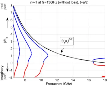
![Figure 3. Dispersion diagram of propagating and one of the complex modes calculated with the same parameters used in [ 18 ], together with superimposed data points from Figure 3 in [ 18 ].](https://thumb-eu.123doks.com/thumbv2/9libnet/4061192.57620/5.739.189.549.323.604/figure-dispersion-diagram-propagating-complex-calculated-parameters-superimposed.webp)
Benzer Belgeler
354 To achieve this goal, the following tasks are solved in the work: conducting a system analysis of models for managing the structuring of materials with a complex
Bu nedenle, ülke içinde tüm illerin turizm sektörü için önemli olan turistik alanları belirlenmesi ve belirlenen önem derecesine göre turizme yön
There are three services generally named as Infrastructure as a Service (SaaS) , Platform as a service (PaaS) and software as a service (SaaS) as provided by cloud
College as emphasized by Sir Syed Ahmad Khan in his writing and speeches was to have such a system of education and training which is the synthesis of western modern education
The turning range of the indicator to be selected must include the vertical region of the titration curve, not the horizontal region.. Thus, the color change
Appendix 4.1 Table of the annual surface runoff (mcm) of the 10 rivers originating from Troodos Mountains.. Appendix 4.2 Table of the predicted annual surface runoff (mcm)
N, the number of theoretical plates, is one index used to determine the performance and effectiveness of columns, and is calculated using equation... N, the number of
As the probability (π) that a gift is the officer’s most preferred choice increases, it is more likely that the dishonest client offers that gift as bribe and achieves his bribery
