KADİR HAS UNIVERSITY
GRADUATE SCHOOL OF SCIENCE AND ENGINEERING
SCHEDULING PUMPED HYDRO-POWER RESOURCES UNDER PRICE AND FLOW UNCERTAINTY
Master Thesis
Seda Sibel METİN
S eda S ibel METİ N M .S . The sis 2012 S tudent’ s F ull Na me P h.D. (or M.S . or M.A .) The sis 20 11
SCHEDULING PUMPED HYDRO-POWER RESOURCES UNDER PRICE AND FLOW UNCERTAINTY
Seda Sibel METİN
Submitted to the Graduate School of Science and Engineering in partial fulfillment of the requirements for the degree of
Master of Science in
Industrial Engineering
KADİR HAS UNIVERSITY October, 2012
vii
SCHEDULING PUMPED HYDRO-POWER RESOURCES UNDER PRICE AND FLOW UNCERTAINTY
Abstract
Hydroelectric power plants should be preferred since they are environmentally friendly and they have low level of potential risks. Hydroelectric power plants are local resources that are environmentally compatible, unpolluted, capable of dealing with peak hour requirements, highly efficient, cost-free of fuel, and playing a role as the insurance of energy prices.
Pumped Hydro Storage Systems are more efficient plants for the storage of electricity. The working principles of the systems are very simple. At peak times or in other words when price of electricity is high, electricity is generated, and at nights during off peak time, in other words when price of electricity is low, water is pumped to upper reservoir from lower reservoir.
We constructed a model to utilize stored water in the most efficient way, to allocate required water for irrigation, to prevent water falling under a specified level and to obtain maximum profit for the investor. For this purpose, we created a formulation by considering all constraints and we obtained optimum schedule since there is a need for efficient performance of the pumped hydro storage systems.
Firstly we have created approximately 10 different LMP scenarios taking 2009 as the base year for the LMP. After this stage using the cluster analysis and grouping the 35 years river inflow rates, totally we achieved 10 different groups. We developed ten scenarios of different LMP prices with ten groups in ten years and we ran the model using by GAMS.
In this thesis we construct a model for scheduling pumped hydro storage system under uncertainty of electricity price and water inflow rates trying to achieve the maximum revenue. Key Words: Scheduling, Pumped Hydro Storage Systems, Electricity Price, Optimization, LMP
viii
SCHEDULING PUMPED HYDRO-POWER RESOURCES UNDER PRICE AND FLOW UNCERTAINTY
Özet
Hidroelektrik santraller kuruluşlarından bu yana sürekli artan enerji ihtiyacını karşılamak üzere enerji piyasasında aktif bir rol üstlenmişlerdir. Temiz, yenilenebilir, pik taleplerine hızlı yanıt verebilen ve çevreyle uyumlu olan bu santraller fosil yakıtların doğaya verdikleri zararlara karşın daha uyumlu ve uzun süre çalışabilmektedirler. Bu santrallerin pompa depolamalı olanları ise var olan su gücünü tekrar kullanma olanağı sağladığı ve üretici için daha karlı bir yatırım aracı olduğu için tercih edilmektedir. Pompa depolamalı hidroelektrik santraller (Pumped Hydro Storage Systems) biri alt diğeri üst olmak üzere iki rezervuarlı sistemlerdir. Üst rezervuardaki jeneratörlerden bazılarında pompa sistemi bulunmaktadır ve elektrik fiyatının düşük olduğu zamanlarda su aşağıdan yukarıya tekrar pompalanmaktadır. Bu çalışma da pompa depolamalı hidroelektrik santraller için fiyat ve nehirlerin akış miktarının belirsizliği altında maksimum karı ve en verimli çalışmayı sağlayan çözümü bulmak üzere bir model oluşturulmuştur. Hazırlanan model 35 yıllık nehir akış miktarları ve değişken elektrik fiyatlarının (LMP) olduğu 10 farklı senaryo için optimizasyon programı GAMS kullanılarak sonuçlar alınmış, ve sonuçlar yorumlanarak beklenen kar miktarları belirlenmiştir.
Anahtar Kelimeler: Optimizasyon, Elektrik Fiyatı, Simulasyon, Hidroelektrik, Pompa Depolamalı Hidroelektrik Sistemler
ix
Acknowledgments
I deeply thank my thesis supervisor, Asst. Prof. Dr. Ahmet Deniz Yücekaya who has supported me; not only for the project, but also for every step of my graduate studies. His suggestions and positive criticism were invaluable during my education and thesis study. I would like to thank my best friend, Ecem; she always helped me planning the project with her big smile. I want to thank my parents for their patience and understanding. And I would like to thank my cousin Kemal; he helped me at preparation of this study. Lastly, I thank my husband, Cem; for the encouragement and the editing. Without his support, I could not finish this project.
x
“I, Seda Sibel METİN, confirm that the work presented in this thesis is my own. Where information has been derived from other sources, I confirm that this has been indicated in the thesis.”
_______________________
xi
Table of Contents
Abstract vii
Özet viii
Acknowledgments ix
List of Tables xiii
List of Figures xv
1 Introduction 1
2 Literature Review 5
3 Pumped Hydro Storage System 8
3.1 Dams and Hydropower Systems 8
3.2 The Working Principle of Dams 8
3.3 Pumped Hydro Storage Systems 9
3.3.1 The Working Principle of Pumped Hydro Storage Systems 13
3.3.2 The Principles of Pumped Hydro Storage Systems 15
3.3.3 Benefits of Pumped Hydro Storage Systems 16
4 Case Study- Smith Mountain and Leesville Lake 17
4.1 Smith Mountain 17
4.2 Leesville Lake 19
5 Problem Formulations for Scheduling of Pumped Hydro Storage Systems 22 6 Solution Methodology for the Scheduling 26
6.1 Modeling Smith Mountain and Leesville Lake 28
7 Numerical Results 35
xii
7.2 Characteristics of Smith Mountain Pumping Units 36
7.3 Characteristics of Leesville Lake Generation Units 36
7.4 Characteristics of Smith Mountain Reservoir 37
7.5 Characteristics of Leesville Lake Reservoir 38
7.6 Locational Marginal Pricing 38
7.6.1 LMP at Smith Mountain in 2009 40
7.6.2 LMP at Leesville Lake in 2009 41
7.7 Inflow Rates from Rivers 41
7.8 Generation Schedule for One Month 44
7.9 Smith Mountain Schedule for One Month 44
7.10 Leesville Lake Schedule for One Month 47
7.11 Pumping Schedule for One Month 49
7.12 Generation Schedule for One Year 50
7.13 Smith Mountain Schedule for One Year 51
7.14 Leesville Lake Schedule for One Year 54
7.15 Pumping Schedule for One Year 55
7.16 Sensitivity Analysis 56 7.16.1 Cluster Analysis 56 8 Conclusion 65 References 66 AP PE ND IX C APPENDIX B
xiii
List of Table
Table 7.1.1 Characteristics of Smith Mountain Generation Unit 35 Table 7.2.1 Characteristics of Smith Mountain Pumping Units 36 Table 7.3.1 Characteristics of Leesville Lake Generation Units 36
Table 7.4.1 Characteristics of Smith Mountain 37
Table 7.5.1 Characteristics of Leesville Lake 38
Table 7.6.1: LMP at Smith Mountain in 2009 40
Table 7.6.2: LMP at Leesville Lake in 2009 41
Table 7.7.1: Inflow at Roanoke River in 2009 42
Table 7.7.2: Inflow at Pigg River in 2009 42
Table 7.7.3: Inflow at Blackwater River in 2009 43
Table 7.7.4: Inflow at Back River in 2009 43
Table 7.8.1: Revenue for 1 Month 44
Table 7.9.1: Smith Mountain Generator 1 45
Table 7.9.2: Smith Mountain Generator 2 45
Table 7.9.3: Smith Mountain Generator 3 46
Table 7.9.4: Smith Mountain Generator 4 46
Table 7.9.5: Smith Mountain Generator 5 47
Table 7.10.1: Leesville Lake Generator 1 48
Table 7.10.2: Leesville Lake Generator 2 48
Table 7.11.1: Smith Mountain Pumping Unit 1 49
Table 7.11.2: Smith Mountain Pumping Unit 3 50
Table 7.11.3: Smith Mountain Pumping Unit 5 50
xiv
Table 7.13.1: Smith Mountain Generator 1 51
Table 7.13.2: Smith Mountain Generator 2 52
Table 7.13.3: Smith Mountain Generator 3 52
Table 7.13.4: Smith Mountain Generator 4 53
Table 7.13.5: Smith Mountain Generator 5 53
Table 7.14.1: Leesville Lake Generator 1 54
Table 7.14.2: Leesville Lake Generator 2 54
Table 7.15.1: Smith Mountain Pumping Unit 1 55
Table 7.15.2: Smith Mountain Pumping Unit 3 55
Table 7.15.3: Smith Mountain Pumping Unit 5 56
Table 7.16.1: Cluster Analysis-Dendrogram 58
Table 7.16.2: Total Revenue in 2009 (Month & Year) 59
Table 7.16.3: Total Revenue for Smith Mountain 60
Table 7.16.4: Total Revenue for Leesville Lake 61
Table 7.16.5: Total Revenue for Pumping Units 62
Table 7.16.6: Probabilities of Groups and LMP Scenarios 63
Table 7.16.6: Total Revenue for All Scenarios 64
xv
List of Figures
Figure 1: Dams Working Principle 9 Figure 2: The Working Principle of Pumped Hydro Storage Systems 13
Figure 3: Pumped Hydro Storage Systems 14
Figure 4: The Principles of Pumped Hydro Storage Systems 15
Figure 5: Smith Mountain Project 17
Figure 6: Leesville Lake 19
Figure7: Satellite Layout of Smith Mountain and Leesville Lake 21
Figure 8: Model Inputs and Outputs 26
Figure 9: General Flow Diagram 27
Figure 10: Sol. Meth. for Modeling Smith Mountain &Leesville Lake 34
1 Chapter 1 Introduction
In today’s increasing energy needs, human beings are forced to utilize resources such as water, wind and sun more efficiently. Rapid population growth and advancements in technology made energy, which is a limited resource, more vital. So what is energy?
Energy is the transformation, in which capacity of a physical system transforms into power to do work. Energy can be observed in many forms: thermal, kinetic, mechanic, luminous, potential and electrical. On the other hand, Power is the time rate at which work is done or energy is transferred.
In the last century, natural resources deplete in a fast manner due to advancements in technology as well as developments in industries and this raises the importance of energy every day. Therefore, it is indispensable to utilize energy efficiently, prevent waste of energy and pull down energy costs. In other words, decrease in energy consumption without reducing life, which means increasing energy efficiency in every field of life, must be achieved. To ensure permanency of energy efficiency, energy efficiency measurements should be done in the light of assuring data, should be evaluated and monitored in some intervals. Efficiency measurement of energy, which is the main input of human life, needs efficient utilization of natural resources. This provides taking positive precautions instead of destructing methods for natural balance.
Main purpose of tending to new energy resources is to protect nature and to make living environment better and qualified. Renewable and environmentally friendly energy resources
2
are needed instead of fossil fuels, which damage human health and generate greenhouse gases that trigger global warming.
Among other renewable energy resources, hydropower is the most efficient. As we know, main input of life of modern man and every economic activity is electricity. With right policies and strategies, this huge power can generate adequate electrical energy. Hydroelectric power plants should be preferred since they are environmentally friendly and they have low level of potential risks.
Potential energy of water due to gravitation can be transformed into electrical energy with hydroelectric power plants. Hydroelectric power plants are local resources that are environmentally compatible, unpolluted, capable of dealing with peak hour requirements, highly efficient (above 90%), cost-free of fuel, and playing a role as the insurance of energy prices.
There are many advantages of hydroelectric power plants. They only require first capital cost. After that, they can continuously generate electrical energy. They do not have any harmful effects neither on environment nor on human health. Hydroelectric power stations are more reliable than solar or wind sources. Compared to other energy resources, they have the least operating cost as well as longest operating life and efficiency. Besides, they compose create minimum risk and negative effects. If we look at the disadvantages, we can see the enormous capital cost of dams at the beginning of the investment. However, this can be solved with cooperation of private sector and government to form a budget partnership. Another problem is to determine the location of dam, which can be solved with correct planning and investigations. One of the biggest disadvantages is the opinion that animals and vegetations of the location can be harmed due to decrease in water quality used in the dam. However, this
3
opinion is in more acceptable borders than other energy resources in terms of harming animals and natural life.
Hydropower generates electrical energy thanks to water cycle, which continues since the existence of the world. If we examine water cycle, water vapor inside oceans and lakes condensates and forms clouds as well as rain at proper conditions. Water falling on earth as raining flows into oceans and groundwater after leaking into soil. After evaporation of water from these locations, water returns to atmosphere. Thus, a continuous cycle of water forms.
As known, hydropower utilizes water as fuel. Water is always inside a process, as it will never diminish since water cycle is infinite in the world. It refreshes and renews itself. Therefore, it is a natural and renewable power.
Hydroelectric power or hydropower is the transformation of flowing water into electrical energy. Hydroelectric plants are in many types and variances. Main characteristic of all of them is to transformation of kinetic energy of down falling water into electrical energy with the help of turbines and generators. Today, the energy generated by this method transmits into our houses, offices and industries as electrical energy. We will examine electric generation and dam structure in detail in Chapter 3.
In the light of all these, we have to use this natural, renewable and enormous power resource correctly and with quality considerations to be able to cope with increasing energy demand, maintain socioeconomic income level and economical growth as well as to be able to leave a clean nature to future generations. To utilize waterpower correctly, we have to plan, research take all possibilities in mind in detail. To make efficient dam systems that have huge investment costs; determination of flow rate, rate of water height from upstream, water amount flowing and amounts allocated for irrigation as well as evaporation should be done. Hydroelectric power plant is a huge complex system in which constraints such as climatic
4
drought periods and precipitation rate of the location exist. Main purpose to construct one of them is to take care of increasing energy demand and provide maximum profit for the investor.
In this thesis, we construct a model for a system with two reservoirs. One of them is higher reservoir and the other one is lower reservoir. First reservoir, which replaced higher, has five generators, three of these generators have pumping unit characteristics, and the lower reservoir has two generators.
In the constructed model, first reservoir is fed by three rivers and lower reservoir is fed by one river. Model is constructed by taking elements that affect electric generation and revenue into consideration. These elements can be listed as uncertainties in flow rates, precipitation rates and variable LMP. In chapter 5, we will give detailed information about Smith Mountain and Leesville Lake reservoir used in our model.
The operational purpose is to maximize the revenue. For this purpose, we created a formulation by considering all constraints and we obtained optimum schedule by using GAMS program. We are going to explain all model and solution methodology in detail at Chapter 4 and Chapter 6.
5 Chapter 2 Literature Review
In this chapter we will investigate scientific side of subject looking for articles and investigation about electricity generation and pumping storage systems made in the past. Firstly, Levine (2003), mentioned about that renewable energy sources gain importance for electric generation and he emphasized that solar energy is not generative because it can not be used at nights. Also he emphasized that wind source is not useful when there is not any breeze. But in spite of these he mentioned that energy generation source must be renewable.
We can also see from this article that using a renewable energy is very important for both people and nature. Also it is very important for maximum energy generatively. With all these investigation, using hydro power, that has needed all energy, harmony with nature and clean and long existence is inevitable.
Hydro power is an important source used for electric generation thanks to dam system made with good plan. We will examine dam system lengthy in another section. But this system that is the most generative and the most harmonious with nature can used for all country’s electric necessity if it is used in the right way.
Yang C. mentioned that pumped hydro storages are the best low-carbon electricity resource because that the other options cannot flexibly adjust their output to match instable electricity demand. Pumped hydro storage systems are more efficient than other low-carbon electricity resources which are nuclear, wind and solar system. Yang indicated that pumped hydro storage systems provide many commercial advantages for the producers. Pumped hydro storage systems serves to stabilize the electricity grid through peak shaving, reserve generation, load balancing and frequency control. Yang noted that while global warming
6
increasing rapidly, developers is working new pumped hydro storage system projects and in 2014 its expected capacity worldwide is 76 GW.
Zhu et al.(2006), mentioned that hydropower plants are prepared with an optimum plan for the least operation cost, maximum reservoir management and maximum proportion of electricity generation.
According to Zhao and Davison (2009), electric generation and consumption should almost be at the same time but the power should not be stored. Because when human life is examined, we see that necessity for electricity is not stable. For example, we know that electric is used too much especially at working hours but it is used less at nights. For this reason, electricity generation at dam can be most generative, with the help of pumping system at electricity generation. When electric demand and electric price is low, electricity generation is made with the help of pumping system.
Zhao and Davison (2009), explained the pumping system in this way that two reservoir are used for pumping system. One of these are big reservoir that is higher than sea level. Another one is lower. Water is pumped from small reservoir the big reservoir at the time of decrease on the energy demand and electricity price so energy is stored. If there is an increase for energy demand and in electricity cost, generating electricity is drived with the turbines at lower reservoir. We will examine detailed information about pumping hydro storage systems at Chapter 3.
Ikudo (2009), mentioned that thanks to pumped storage hydroelectric station, water is stored at high altitude again and so when electric demand is low, water is reused for generating electricity. And power demand is high, it is directly used for generating electricity with the help of the turbines. Besides, pumping systems do not directly affect but it only increases maximum gain that is got when there is an increase or decrease of electric prices that is named
7
peak time or off-peak time. In the same research Ikudo (2009), told us that each pumped hydro storage system is different from each other. Each one has different in reservoir numbers. Water that is from different rivers is used in them. Power rate of dam and water inflow can be different. Their generators and pumping numbers are different as well as any other factors affecting this system. Because of all these factors, it should be made a different scheduling for each pumped hydro storage systems.
According to Bushnell (1998), generating electricity by hydroelectric power plants is very important and primary source but according to common view it does not store electricity. So obtaining of hydroelectric energy source’s controls depends on determined distains like water rate accumulating in reservoir. However it should be enough and fast when electric demand is high.
Ikudo (2009), in another article, mentions that many uncertain constraints arise while the pumped storage hydro facility operation is planning, and to manage them is very important. Also she mentions the importance of managing the water resources, under the situations of uncertain amounts of water coming into the reservoirs and uncertain flow-rate between the multiple reservoirs. Ikudo tells that, many optimization methods are published about this subject and the studies are at the phase of meeting the demands. But the main purpose of the coming up of the pumped storage hydro facility is to convey the gross margin to the maximum level.
Through the literature, we understand the pumped hydro storage systems are more efficient and essential low-carbon level resource. For this reason planning for the system should be regularly. Since our objective is to maximize the gross margin under electric price and inflow rate uncertainty. The aim of this thesis is to establish a model which has optimum schedule for maximum revenue under price and flow uncertainty.
8 Chapter 3
Pumped Hydro Storage System
Zhao and Davison (2009), mentioned that pumped storage plants consist of two reservoirs. And one of them is positioned in an upper level than the other one. When electric demand is low and electric price are both low, electric is storage pumping from lower reservoir to upper reservoir by pumping hydro storage system. When energy demand is high or electric costs are increased, water generates electricity by driving turbines, also at lower reservoir after the upper one.
3.1 Dams and Hydropower Systems
Dams are constructions that are built to store water and to move water where it is demanded. Big or small, all types of dams are buildings that are planned to get energy for necessity of people, to use appropriate and sufficient water for agricultural lands. Almost %75 of dams is designed to irrigate agricultural lands, generate electricity for these two aims. Principal aim of building of a dam is that water in stream and river are planned according to the needs of people without damaging natural equilibrium. There are lots of big or small dams for this aim. It is a system that dam’s types, managing system, place have variety and depend on different conditions. Also, according to the types of dams, dam heights, reservoir numbers and areas are extremely important factors.
3.2 The Working Principle of Dams
Dams are generally built near lakes and they control water by trapping. Water that is stored at reservoirs of dam starts to drive turbines of dam by going to tunnels. Turning movement helps to move simple magnetic system so the generations of electricity take place. The most
9
important point is water’s potential power and pressure on the lower levels. In this way hydro power plant can generate very high power with low investment costs. Flowing water which has natural potential energy of gravity turns into electric energy by dams. Because of this we know that it is possible to get more energy with following water from higher point. For this reason mountainous countries get energy that they need from these natural and cheap hydroelectric power stations because of their location.
Figure 1: Dams Working Principle. Source: [15]
3.3 Pumped Hydro Storage Systems
The system is based on pumping water to relatively high reservoir from a lower reservoir when the demand and the instantaneous price for electricity is low and generating electricity when the demand and instantaneous price for electricity is high. The generating electricity is drive by waters rush down. The used water is stored at the lower reservoir, and that’s one cycle for this process. Pumped hydro storage systems do not truly generate electricity. They store energy, to react rapidly under the high electrical demand situations. As known, the demands for electricity changes in every season, month, and day and even at the different times of a day. As an example of, when the most watched TV programmed is on, millions of people turn on television which means a serious demand increase in electricity. Many other
10
examples for sudden demand increasing can be described. If the electrical power plants can not react rapidly to meet the demand, the system frequency goes down, units go of and power outage occurs which brings many problems. Electric cut-outs may cause negative results on social life. Any problem inside the generating plant, may decrease generating efficiency or may cut the power generating. This can make traffic lights out of service, accidents, injuries even deaths there may be. Therefore the systems plan for meeting the demand should be well, and should react rapidly.
If the most of the electricity is generated by the fossil fuels, which takes nearly half an hour to reach at full capacity, or nuclear power plants, which take even more time from fossil fuel generating systems to get ready to generate, it is inevitable to encounters some problems because of the slow reaction time. To avoid those problems or minimize them, on sudden demand increases, reserve should meet the demand in 20-30 seconds. On much more demand increases, there should be power plants which can react in a few minutes.
To obtain the energy right on the exact time we need, Pumped hydro storage reservoirs are developed which differs from other power plants, when the subject is quick reacting and low costing.
First Pumped hydro storage power plants are used in 1890, in Italy and Sweden. In early 1930s they are started to build foe commercial purposes. But the major advancement took place after the Second World War. In recent years, especially in Europe, with the liberalization of the electricity market, basic investment decisions are changed, and because of the peak hours high costs, these plants are looked like cash machines.
Modern life’s any kind of economical and various fields of social life are based on electricity. Just because of that, power demand safety policies should be developed, and these policies should be determined considering supplying the demand points, the proper voltage and
11
frequency of electricity, and resistant systems that can not malfunctioned at a simplest defect. To meet the highest demand, a reasonable amount of reverse capacity should always be ready to use. There are two types of reliability of supply. First one is short-terms of reliability of supply; meeting the demand continuously and qualified. The other one is reliability of supply on long-terms; investing of sufficient capacities.
The pumped hydro storage power plants are suitable to provide the reliability of supply on short-terms. Thus, to provide reliability of supply on long-terms, the pumped hydro storage systems should take place inside the investments for sufficient capacities.
Storage of the energy as in the form of electricity is expensive and is not efficient technologically. Thus, the storage systems are storing energy in the other forms of electricity. Examples for these systems are magnetic energy, electricity energy, mechanical energy, and chemical energy.
Those systems are use in different purpose. If huge amounts of energy wanted to be stored, the most efficient and economical systems are pumped hydro storage systems and compressed air storage systems. These two have the capacity of more than 100MW that can continue about a few hours. Other systems can not provide these values. But pumped hydro storage systems are more efficient, compared to compressed air storage systems. In addition, pumped hydro storage systems are long-live systems and they have the lowest operating costs. These factors are increasing pumped hydro storage systems prefer ability. But the high costs of investment and the long-term paybacks are the disadvantages for pumped hydro storage systems.
The hall pumped hydro storage systems existing on the world have 100.000MW power at total. The most commonly used technique in storing energy is pumped hydro storage systems. Particularly in Japan, pumped hydro storage systems are widely used in many countries.
12
If we examine pumped hydro storage systems; at first, huge and central pumped hydro storage systems were in use. Technological infrastructure and economical contribution of pumped hydro storage systems are proven, and they have open structures for new developments. Thus the number of pumped hydro storage systems is increasing today. The system basically converts the low-cost electricity to the high-cost electricity and provides the opportunity to make commercial profit.
Wind energy is the second most common commercially used renewable energy source after hydroelectric power plants. But wind energies formation rate can not be estimated exactly, and also intermittent movements can exist. Thus, it needs another integrated model to provide the systems and security demands. For an optimum operating, to balance the voltage and to provide the stability of the voltage and frequency, wind power plants must be integrated with hydroelectric plants or pumped hydro storage systems. Thus the importance of pumped hydro storage systems increased in recent years.
Smaller and decentralized pumped hydro storage systems are only used for converting the energy prices to higher rates. They do not balance the voltage or provide ancillary services. This system is directly linked to the original energy market conditions and infrastructure. If the infrastructure is already exists and does not need high constructing costs, it may be a significant investment to build the system. In some regions, where increasing the capacity is not possible due to environmental factors, in the peak times, the problem is solved by giving energy to their system and saving energy when the demand is low, so that there is no requirement for high transmission capacity.
13
3.3.1 The Working Principle of Pumped Hydro Storage Systems
Figure 2: The Working Principle of Pumped Hydro Storage System. Source: [16]
Pumped Hydro Storage System conclude lower an upper reservoirs, and a power conduit between the two reservoirs, an electricity generating or water pumping turbines and generator groups, hydro mechanical and electromechanical equipments related to these units.
This is the technology description of pumped hydro at ESA (2012); “Conventional pumped hydro uses two vertically-separated water reservoirs. During off peak hours water is pumped from the lower reservoir to the upper reservoir. When required, the water flow is reversed to generate electricity. Some high-dam hydro generating plants have a storage capability and can be dispatched as a pumped hydro. Underground pumped storage, using flooded mine shafts or other cavities, is also technically possible. The sea can also be used as lower reservoir. A 30 MW seawater pumped hydro plant was built near Yanbaru, Japan, in 1999.”
When the power demand is low, at nights, water is pumped up to the top reservoir. In case of a sudden power demand increase, the powerful generators starts working by the drive of turbines, which are drived by the water, that started rushing down after the opening of the head gates or the huge taps. After the process, the water is collected in the bottom reservoir
14
till the next low power demand period for pumping back up. Dinorwig is the quickest pumped storage plant in the world when the subject is “response time”.
The increasing of height for water by pumping up brings gravitational potential energy that can be stored in the top reservoir. The height and stored energy is directly proportional to each other. Because of that, Dinorwig site, having two lakes, which have seriously height difference from each other, was chosen. This means less work was needed for building the station.
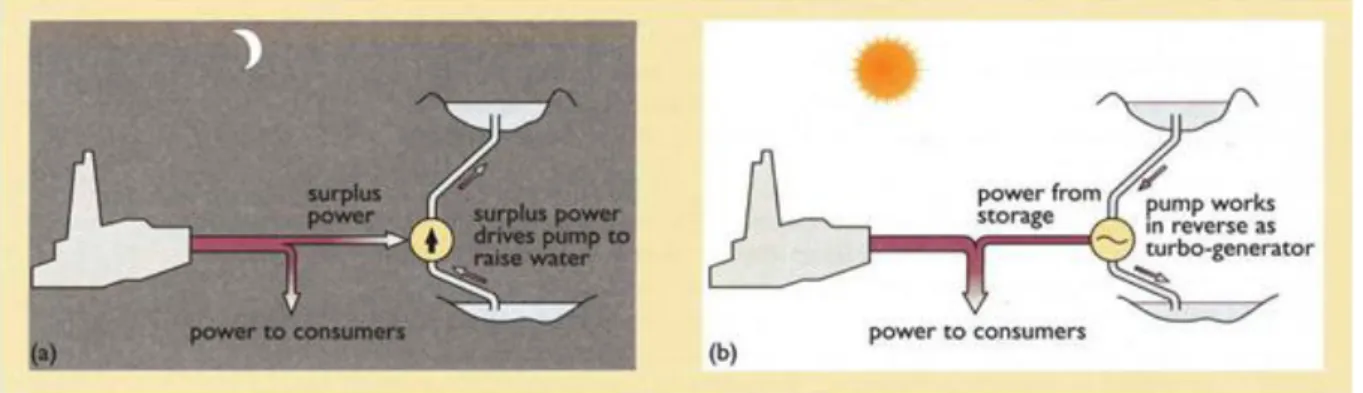
Before arriving the turbines, water falls about 600-700 meters. This height generates a great pressure especially near the end. Because of this, the bottom parts and the tunnels are lined with steel. Dinorwig system is designed to pump water from the lower to the upper reservoir, as it can generate electrical power by turbines.
Figure 3: Pumped Hydro Storage System: (a) at time of low demand; (b) at time of high demand. Source: [16]
15
3.3.2 The Principles of Pumped Hydro Storage Systems
The energy is created by the down flowing of the water through high pressure shafts that are linked to turbines. Then the turbines drive the generators to create electricity. That means the system is requiring a high altitude (relatively) reservoir, which water can down flow.
After processing these, now water will be pumped back to the high altitude reservoir .Now that means the system is requiring a second reservoir that situated at the bottom, to collect the used water which will be pumped back to the upper reservoir. Also the system is requiring a pump shaft, which is linked to the turbine shaft, to pump back the water. And also a motor, to drive the pump, is needed. Those pump motors are taking the electrical power from the National Grid, and it is usually processed after midnight, when the national demand is the lowest. From the lines upper, we can see that pumped storage generation provides a critical back-up facility, when the demand is excessive on the national grid system.
16 3.3.3 Benefits of Pumped Hydro Storage Systems
The Pumped Hydro Storage Systems can balance the voltage and provide assistant services as they can shear peak. By rapid responding and rapid reacting; hydro power plants generates high amount of energy in a few minutes, to meet the high demand. Voltage balancing is another benefit of system stability, the voltage and frequency has significance for many industrial consumers as un-stabilized voltage can harm the machines and can stop production. Therefore, industrial associations use pumped hydro storage systems to get balanced voltage. Also the black-start is a great ability. These power plants start operating mains-independent. Hydroelectric power plants are usually mains-independent can start operating by itself, but other plants cannot. Another important benefit of pumped hydro storage plants are storage of the energy. When price of the electricity is low, by pumping the water to an upper reservoir and storing it there, and when the price increased on the peak times, generating the electrical energy, and storing the water inside the lower reservoir, is the main basic for this system.
17
Chapter 4: Case Study
Smith Mountain and Leesville Lake 4.1 Smith Mountain
Smith Mountain project was build to generate hydro-electric power with two reservoirs in the near by the Roanoke River, Virginia. This project engineer is the Appalachian Power. This Project is the unique pumped-storage system which is provides electricity for region concurrently with its most important for the region’s economy. It is also used to tourism and outdoor activities. Smith Mountain project is built on the Roanoke River in the mid-1960s.This Project includes two dams and reservoirs. They compass about 600 miles of shoreline and get round about 25,000 surface acres of water for different uses.
Smith Mountain Pump Storage Hydroelectric Project was realized that the damming for Roanoke River which is the plans for many years. This idea proposed in the 1920s but 40 years later the Appalachian Power began the two dams’ building- which is the unique project- in 1960 and completed in 1963. Hundreds of workers cleared several hundred cubic feet of mountainside and poured about 200,000 cubic feet of concrete to build the project.
18
The two lakes of the project are reached full level in 1966.The reservoir areas were primarily rural farmland. Appalachian Power built several bridges to accommodate the traffic around the lakes, during the dam construction. Smith Mountain and Leesville Lake combination have 600 miles of shoreline, 25,000 surface areas inside 60 miles length.
Appalachian Power, that is a subsidiary of American Electric Power (AEP), is licensed by Federal Energy Regulatory Commission (FERC) to operate the Smith Mountain Project. In 2010, the new license issue started, that is covering 30 years term. The initial license was for fifty years.
As Smith Mountain, pumped storage system is used for producing electricity. The upper reservoir in the whole systemic Smith Mountain and Leesville Lake serves as the lower reservoir.
The water coming from Smith Mountain Lake, produces electricity in the powerhouse by passing through the turbine generators, and then gets evacuated into Leesville Lake. The retained water inside the Leesville Lake is pumped back to Smith Mountain Lake to use it again and again. To generate additional energy, a part of water goes to turbine generators at Leesville powerhouse. It is also necessary to meet the minimum discharge requirements of the project’s Federal Energy Regulatory Commission (FERC) license.
During the power generating by the passing water though the turbines, two feet decrease of the Smith Mountain lakes water, makes thirteen feet increase in the level of the Leesville Lake. The minimum elevation is 600 feet and the maximum elevation is 613 feet for Leesville Lake. After 613 feet, Leesville is full, and Smith Mountain cannot generate power. The generation starts again when some portion of the water is pumped back to Smith Mountain Lake.
19
A constant operating schedule does not exist, because generation is usually performed when the demand for electricity is high. Pumping back the water to upper reservoir is usually performed when the electricity demand is low. The operation can change depending on demand for electricity. But the change is on an hourly basis.
Smith Mountain is 795 feet at full pond elevation. But full pond conditions continue till 793 feet by the presence of the two foot power pool. Smith Mountain pond elevation may fall below 793 feet under low-inflow conditions.
4.2 Leesville Lake
20
Leesville Lake contains nearly 5000 surface acres on 100 miles of shoreline, which are inside the hall 20 miles length of the lake. According to the Project values, 620 foot contour elevation as boundary, and 600 to 613 foot contour elevation for the fluctuating band, is determined.
Smith Mountain project is a pumped storage hydroelectric power plant, which has the capacity of 636 MW. An upper reservoir (Smith Mountain) and a lower reservoir (Leesville Lake) are being utilized by the facility. The water coming from the Smith Mountain Lake drives the turbine generators inside the powerhouse in purpose of generating electricity. After the process, water stored in the upper reservoir is being discharged into Leesville Lake, and pumped back to the upper reservoir to use it again and again. In order to generate additional electricity and compensate the minimum discharge requirements of the project’s operating license, with a portion of water, Leesville power houses turbine-generators are actuated.
21
Figure 7: Satellite layout of Leesville Lake and Smith Mountain. Source: [32]
Satellite layout of Leesville Lake and Smith Mountain lakes can be seen in Figure 7. Rivers feeding these two reservoirs can be seen apparently. Shoreline and agricultural fields as well as branches of various rivers were investigated and rivers feeding above mentioned lakes were chosen to model optimum revenue obtained from reservoirs. Rivers feeding reservoirs are Roanoke, Back, Blackwater and Pigg River.
22 Chapter 5
Problem Formulation for Scheduling of Pumped Hydro Storage Systems
The operational purpose is to maximize the revenue of operation. For this purpose, we created a formulation by considering all constraints and we obtained optimum schedule since there is a need for efficient performance of the pumped hydro storage systems. Model can be run on weekly, monthly and daily basis. For each basis, planning can be done for the optimum result individually.
Now we give the notation for the formulation Notation (Source : [8])
= Power market price during hour t in first reservoir ($/mwh) = Power market price during hour t in second reservoir ($/mwh) = Power generated at first reservoir by unit i in hour t (mw) = Power generated at second reservoir by unit j in hour t (mw)
= Power used for pumping by unit k during hour t (mw) = Capacity of first reservoir by unit i (mwh)
= Capacity of second reservoir by unit j (mwh) = Capacity of pumping unit (mwh)
= Volume of first reservoir at the end of hour t (f ) = Volume of second reservoir at the end of hour t (f ) = Inflow to first reservoir during hour t (f )
= Inflow to second reservoir during hour t (f ) , = Inflow from rivers a and b (f )
= Spillage from first reservoir in hour t (f ) = Spillage from second reservoir in hour t (f )
23 = Yield (efficiency) of pump k (ft3/mw)
= Yield (efficiency) of generator i in first reservoir (ft3/mw) = Yield (efficiency) of generator j in second reservoir (ft3/mw)
= Minimum and maximum limits of first reservoir in hour t (f ) = Minimum and maximum limits of second reservoir in hour t (f )
General Model
We modeled a typical pumped hydro system. The related notation is given above. The objective of the system is to maximize the operational profit over some time period.
Objective Function
Max (5.1)
The problem is subject to following constraints; Capacity Constraints (5.2) (5.3) (5.4) (5.5) (5.6) (5.7) (5.8) (5.9) (5.10)
24
Eq. (5.1) represents the objective function which is revenue minus cost. The first part of the equation is the operational revenue from the power sales of Smith Mountain. This is represented as power generation multiplied by the power price at Smith Mountain. Second part is operational revenue from the power sales of Leesville Lake. It represented as power generation multiplied by the power price at Leesville Lake. These parts are sum and minus the final part which is the show that pumping cost. This is represented as power generation multiplied by the power used for pumping.
Eq. (5.2) is the first capacity constraint. It is defined that first reservoir has limited capacity at in time. It is not larger than first reservoir capacity or smaller than 0.It should be equal or between these capacities.
Eq. (5.3) is the second capacity constraint. It is defined that second reservoir has limited capacity at in time. It is not larger than second reservoir capacity or smaller than 0. It should be equal or between these capacities.
Eq. (5.4) is the last capacity constraint. It is defined that capacity of pumping unit at in time .It is not larger than pumping capacity or smaller than 0. It should be equal or between these capacities.
Eq.(5.5) symbolizes that all power generated at first reservoir by unit i in hour t multiply by power used for pumping by unit k during hour t are equal to 0.
Eq. (5.6) states that volume of first reservoir at time t equals to sum of reservoir volume at time t-1 and total volume of pumped water extracted by total generated power plus total inflow rate in time t.
25
Eq. (5.7) defines that volume of second reservoir at time t equals to extraction of reservoir volume at time t-1 and total volume of pumped water subtracted by total generated power in first reservoir in time t minus total generated power in second reservoir in time t plus total inflow rate in time t.
Eq. (5.8) is the first volume constraint. It is defined that first reservoir has limited volume at in time t. It is not larger than first reservoir’s maximum volume level at the end of time t or smaller than minimum volume level at the end of time t. It should be equal or between these volume levels.
Eq. (5.9) is the second volume constraint. It is defined that second reservoir has limited volume at in time. It is not larger than second reservoir’s maximum volume level at the end of time t or smaller than minimum volume level at the end of time t. It should be equal or between these volumes levels.
Eq. (5.10) shows the total inflow to first reservoir during hour t which is coming from river A and river B.
26 Chapter 6
Solution Methodology for the Scheduling
Main inputs of the model are annual inflow rates of Roanoke River, Back River, Blackwater River and Pigg River, daily based variable price of electricity in one year namely LMP and lastly general characteristics of used generators in the model.
Model takes these three critical inputs to compose the optimum schedule. If we are to examine outputs of the model, it gives solutions to the most important questions such as how generation schedule will be, what pumping strategy will be or in other words when electricity will be generated and when pumping system will be activated. As known, investor will make huge profits using pumping system when price of electricity and demand is low. Model is able to form the best and profitable schedule for generation and pumping storage system.
Figure 8: Model Inputs and Outputs
MODEL Inflow LMP Generator Characteristic s Generation Schedule Pumping Schedule Revenue
27
While forming model to prepare optimum schedule, LMP data used in USA in 2009, inflow rates of Roanoke River, Back River, Blackwater River and Pigg River in 2009 are calculated in tabular format and arranged with the help of Microsoft Office Excel. Firstly, optimization codes are prepared by GAMS. After that, optimum result is obtained again with using GAMS. General flow can be seen in the below figure.
General Flow Diagram
Figure 9: General Flow Diagram
Return Schedule Start
Get LMP Daily Data
Get Rivers Inflow Rates
Convert to Hourly Data
LMP for Smith Mountain
LMP for Leesville Lake
28 6.1 Modeling Smith Mountain and Leesville Lake
At peak time or in other words when price of electricity is high, electricity is generated, at nights in off peak time in other words when price of electricity is low water is pumped to upper reservoir. If price of electricity is at medium levels, electricity is generated from both of reservoirs. Therefore, we constructed a model to utilize stored water in the most efficiently way, to allocate required water for irrigation, to prevent water falling under a specified level and to obtain maximum profit for the investor.
Max + - (6.1)
Assumptions
Assume 5 generators at Smith Mountain Assume 2 generators at Leesville Lake Assume 3 pumping units at Smith Mountain
Assume at unit generator1, generator 3 and generators 5 are pump
Generation or pumping at Smith Mountain then unit 1, 3 and 5 are on or off.
= (6.2) = (6.3) (6.4) (6.5) (6.6) (6.7)
29 (6.8) (6.9) (6.10) (6.11) (6.12)
Delay constraints (If generation at t at least 1 hour is needed t switch to pump)
(6.13) (6.14) (6.15) (6.16) (6.17) (6.18) (6.19) (6.20) (6.21) (6.22) (6.23)
30 (6.24) (6.25) (6.26) (6.27) (6.28)
Eq. (6.1) represents the objective function which is revenue minus cost. The first part of the equation is the operational revenue from the power sales of Smith Mountain. This is represented as power generation multiplied by the power price at Smith Mountain. Second part is operational revenue from the power sales of Leesville Lake. It represented as power generation multiplied by the power price at Leesville Lake. These parts are sum and minus the final part which is the show that pumping cost. This is represented as power generation multiplied by the power used for pumping.
Eq. (6.2) If 1st unit in the first reservoir generates electricity, the generation value equals to the multiplying of the capacity and coefficient which determines whether electricity will be generated or not.
Eq. (6.3) If 3rd unit in the first reservoir generates electricity, the generation value equals to the multiplying of the capacity and coefficient which determines whether electricity will be generated or not.
Eq. (6.4) If 5th unit in the first reservoir generates electricity, the generation value equals to the multiplying of the capacity and coefficient which determines whether electricity will be generated or not.
31
Eq. (6.5) If 2nd unit in the first reservoir generates electricity, the generation value equals or smaller than to the multiplying of the capacity and coefficient which determines whether electricity will be generated or not.
Eq. (6.6) If 4th unit in the first reservoir generates electricity, the generation value equals or smaller than to the multiplying of the capacity and coefficient which determines whether electricity will be generated or not.
Eq. (6.7) is the Leesville Lake’s capacity constraint. It is defined that second reservoir has limited capacity at in time. It is not larger than second reservoir capacity or smaller than 0.It should be equal or between these capacities.
Eq. (6.8) shows that either pumping unit in first unit of Smith Mountain is pumping at its capacity or it is not pumping at all.
Eq. (6.9) represents that either pumping unit in second unit of Smith Mountain is pumping at its capacity or it is not pumping at all.
Eq. (6.10) symbolizes that either pumping unit in third unit of Smith Mountain is pumping at its capacity or it is not pumping at all.
Eq. (6.11) shows whether unit i generates electricity or not. If it does, it equals to 1.If it does not it equals to zero.
Eq. (6.12) shows whether unit i is pumping or not. If it is, it equals to 1.If it is not it equals to zero.
Eq. (6.13) shows that sum of whether first unit in time t generates electricity or not and whether first unit at time t+1 generates electricity is equal or smaller than 1.Because both generation and pumping cannot work at the same time.
32
Eq. (6.14) symbolizes that sum of whether third unit in time t generates electricity or not and whether third unit at time t+1 generates electricity is equal or smaller than 1.Because both generation and pumping cannot work at the same time.
Eq. (6.15) represents that sum of whether fifth unit in time t generates electricity or not and whether fifth unit at time t+1 generates electricity is equal or smaller than 1.Because both generation and pumping cannot work at the same time.
Eq. (6.16) shows that sum of whether first unit in time t+1 generates electricity or not and whether first unit at time t generates electricity is equal or smaller than 1.Because both generation and pumping cannot work at the same time.
Eq. (6.17) shows that sum of whether third unit in time t+1 generates electricity or not and whether third unit at time t generates electricity is equal or smaller than 1.Because both generation and pumping cannot work at the same time.
Eq. (6.18) shows that sum of whether fifth unit in time t+1 generates electricity or not and whether fifth unit at time t generates electricity is equal or smaller than 1.Because both generation and pumping cannot work at the same time.
Eq. (6.19) to (6.23) shows that generation and pumping cannot be done at the same time. If generators generate electricity, pumping should not occur. At the period when generator 1, 3 and 5 are pumping, they are not generating electricity because LMP is low. Therefore, electricity generation is not profitable.
Eq. (6.24) states that volume of first reservoir at time t equals to sum of reservoir volume at time t-1 and total volume of pumped water extracted by total generated power plus total inflow rate in time t.
33
Eq. (6.25) defines that volume of second reservoir at time t equals to extraction of reservoir volume at time t-1 and total volume of pumped water subtracted by total generated power in first reservoir in time t minus total generated power in second reservoir in time t plus total inflow rate in time t.
Eq. (6.26) is the first volume constraint. It is defined that first reservoir has limited volume at in time t. It is not larger than first reservoir’s maximum volume level at the end of time t or smaller than minimum volume level at the end of time t. It should be equal or between these volume levels.
Eq. (6.27) is the second volume constraint. It is defined that second reservoir has limited volume at in time. It is not larger than second reservoir’s maximum volume level at the end of time t or smaller than minimum volume level at the end of time t. It should be equal or between these volumes levels.
Eq. (6.28) shows the total inflow to first reservoir during hour t which is coming from river a and river b.
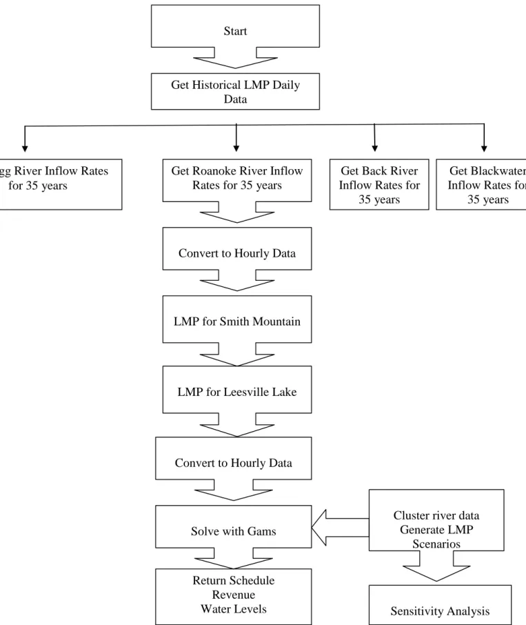
Solution Methodology for Modeling Smith Mountain and Leesville Lake
The solution methodology starts by getting LMP data from data base. The river data Roanoke River, Back River, Blackwater River and Pigg River is getting from historical data. Then we convert to hourly data. We get LMP for Smith Mountain and Leesville Lake and convert to hourly data. These data is taken from MS EXCEL tables and river inflow rates are found by using Cluster analysis method at MINTAB. After that, return schedule, water levels and revenue are solved by GAMS. According to found solutions, sensitivity analyses are done for different scenarios to reach optimum revenues.
34
Figure 10: Solution Methodology for Modeling Smith Mountain and Leesville Lake
Get Historical LMP Daily Data
Return Schedule Revenue Water Levels
Get Back River Inflow Rates for
35 years
Get Blackwater Inflow Rates for
35 years Get Pigg River Inflow Rates
for 35 years
Sensitivity Analysis Start
Get Roanoke River Inflow Rates for 35 years
Convert to Hourly Data
LMP for Smith Mountain
LMP for Leesville Lake
Convert to Hourly Data
Solve with Gams
Cluster river data Generate LMP
35 Chapter 7 Numerical Results
In this chapter, the solutions linked to the running model will be analyzed. The results obtained from the GAMS will be examined in detail under individual headings. Model which we have developed to form optimum schedule uses the time of generation at Smith and Leesville reservoirs, time at which working of pumping system will be required and revenues obtained at monthly and annual based.
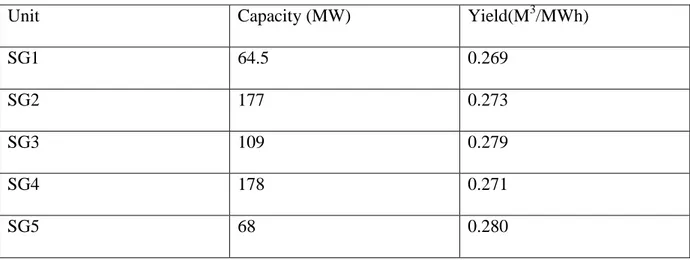
Firstly; we developed a numerical study for the Smith Mountain, Leesville Lake reservoir system. Table 7.1, Table 7.2 and Table 7.3 show figures of all generators and pumping units’ capacities and yield rates. You can examine the tables below.
7.1 Characteristics of Smith Mountain Generation Units
Table 7.1.1: Characteristics of Smith Mountain Generation Units
Unit Capacity (MW) Yield(M3/MWh)
SG1 64.5 0.269
SG2 177 0.273
SG3 109 0.279
SG4 178 0.271
SG5 68 0.280
This table shows that Smith Mountain has 5 generator and each generator has different capacities and yield rates. Yield rate means; requirement of 0.296 M3 water to generate 1 MW electricity. Smith Mountain Generator one is (SG1) 64.5(MW) capacity and its yield rate is 0.269 (M3/MWh).Second generator’s (SG2) capacity is 177(MW) and yield rate is
36
0.273(M3/MWh). SG3 is the third generator in Smith Mountain, its capacity 109(MW) and yield rate is 0.279 (M3/MWh).Forth generator (SG4) capacity is 178(MW) and yield rate is 0.271(M3/MWh).And the last generator SG5’s capacity is 68(MW) and yield rate is 0.280 (M3/MWh).
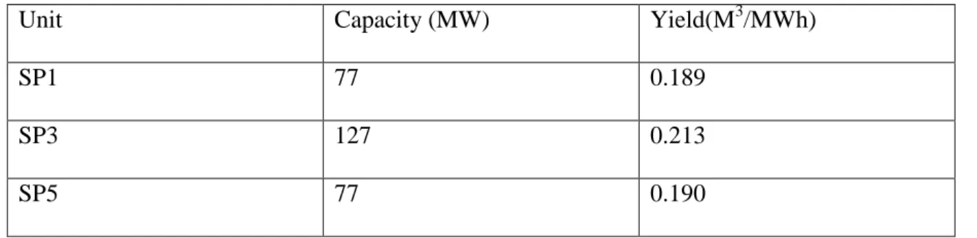
7.2 Characteristics of Smith Mountain Pumping Units
Table 7.2.1: Characteristics of Smith Mountain Pumping Units
Unit Capacity (MW) Yield(M3/MWh)
SP1 77 0.189
SP3 127 0.213
SP5 77 0.190
This table shows that Smith Mountain pumping units. It has 3 pumping unit and each unit has different capacities and yield rates. Yield rate means; requirement of 0.189 M3 water to generate 1MW electricity. Smith mountain pumping unit one is (SP1) 77(MW) capacity and its yield rate is 0.189 (M3/MWh).Second pumping unit (SP3) capacity is 127(MW) and yield rate is 0.213(M3/MWh). SP5 is the third pumping unit in Smith Mountain, its capacity 77(MW) and yield rate is 0.190 (M3/MWh).
7.3 Characteristics of Leesville Lake Generation Units
Table 7.3.1: Characteristics of Leesville Lake Generation Units
Unit Capacity (MW) Yield(M3/MWh)
LG1 22 0.736
LG2 22 0.736
This table shows that Leesville Lake has 2 generator and each generator has same capacities and yield rates. Yield rate means; requirement of 0.736 M3 water to generate 1 MW electricity
37
Leesville Lake Generator is (LG1) 22(MW) capacity and its yield rate is 0.736 (M3/MWh).Last generator’s (LG2) capacity is 22(MW) and yield rate is 0.736(M3/MWh). 7.4 Characteristics of Smith Mountain Reservoir
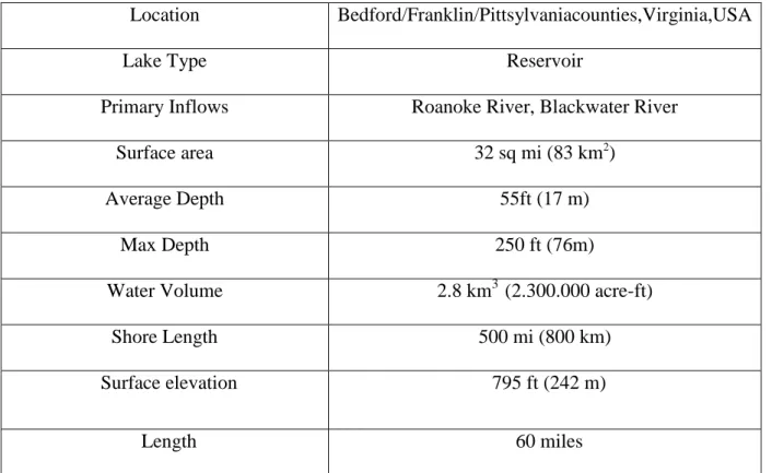
In this part we included the Smith Mountain reservoir characteristics which we use to model. As mentioned before Smith Mountain reservoir has five generators, three of which have pumping system. We will see some important information about location, rivers which feed reservoir and surface area of Smith Mountain which is the most important income source of the system. Table 7.4.1 represents all necessary data about Smith Mountain reservoir.
Table 7.4.1 Characteristics of Smith Mountain Reservoir
Location Bedford/Franklin/Pittsylvaniacounties,Virginia,USA
Lake Type Reservoir
Primary Inflows Roanoke River, Blackwater River
Surface area 32 sq mi (83 km2
)
Average Depth 55ft (17 m)
Max Depth 250 ft (76m)
Water Volume 2.8 km3 (2.300.000 acre-ft)
Shore Length 500 mi (800 km)
Surface elevation 795 ft (242 m)
Length 60 miles
38
In this section we included the Leesville Lake reservoir characteristics which we use to model. As mentioned before Leesville Lake reservoir has two generators, and there no any pumping system. Now we will see some important information about location, rivers which feed reservoir and surface elevation of Leesville Lake. Table 7.5.1 represents all necessary data about Leesville Lake reservoir.
Table 7.5.1 Characteristics of Leesville Lake Reservoir
Location Pittsylvania/Bedford,Campbellcounties,Virginia,USA
Lake Type Reservoir
Primary Inflows Pigg River
Surface area 3,270 acres (13.2 km2)
Surface elevation 548 ft (167 m)
Max Depth 31 ft (9.4 m)
Length 20 miles
Shoreline 100 miles
7.6 Locational Marginal Pricing (LMP)
In this section we will see changes at LMP prices of Smith Mountain and Leesville Lake in 2009. We are going to examine these changes of reservoirs in detail at table 7.6.1 and table 7.6.2 but before that we are going to explain what LMP is and what benefits are included in it?
When there is a congestion on the bulk power grid, the efficiency of the transmission system is managed by locational marginal pricing (LMP), which is a market-pricing approach. Serving the demand, when one or more restrictions on the transmission system prevents the economical, or least expensive supply of energy, arises congestion. Imagine that, in a certain
39
place, transmission lines do not have the capacity to carry the electricity to meet the demand. This problem is named as “Transmission constraint”. The cost of supplying of the more expensive electricity from nearly locations, are included in LMP. And it also provides a market based method for pricing the energy, considering the “cost of congestion”.
In every location of the grid, demands for electricity are priced correctly by LMP. Those prices reveal the locating new generation, upgrading transmission, or reducing electricity values. And these consummation values are needed for the market to be well-functioning thus it alleviates constraints, increases competition and improves the systematic ability to meet power demand.
In LMP, calculation of prices are made under three types of locations, that differs it from New England’s SMD based original market, which has only one energy clearing price. These locations are the node, the load zone and the hub. After the summiting of the offers and bids, settling of the markets, LMP’s are being calculated at these locations.
Benefits of the LMP
When the economically priced power, from flowing to where needed, is prevented by constraints, LMP is pricing the efficient use of the transmission system. LMP improves whole sale electricity market in the short term by ensuring the effected electricity prices from the cost of congestion and again ensuring that least-coast supply is delivered considering physical limits of the transmission network. LMP helps solving congestion problems by promoting efficient investment decisions by creating signal reflecting to the locational value of electricity. Participants can determine the congestion locations and understand the importance of investing transmission, generation and demand response programs.
40
The competitiveness of the energy market would be increased by well located additional generations, rapid demand responses and good transmissions. Increasing the number of suppliers which are competing with each other enforces market discipline without administrative measures. By the help of imported power or lower-cost generators, the price will be competitive. Increased competition results in a more efficient energy market in anyway.
7.6.1 LMP at Smith Mountain in 2009
Following table shows that Smith Mountain reservoir’s LMP values in 2009. It is seen that sudden fluctuations occur when tables are examined. This is because of the fact that river inflow rates and energy demand’s increase and decrease during a year.
41 7.6.2 LMP at Leesville Lake in 2009
Following table shows that Leesville Lake reservoir’s LMP values in 2009. It is seen that sudden fluctuations occur when tables are examined. This is because of the fact that river inflow rates and energy demand’s increase and decrease during a year.
Table 7.6.2: LMP at Leesville Lake in 2009
7.7 Inflow Rates from Rivers
Below four tables show daily inflow rates (M3/h) of Roanoke River, Back River, Blackwater River and Pigg River which feed Smith Mountain and Leesville Lake reservoirs in 2009. It is seen that sudden fluctuations occur when tables are examined. This is because of the fact that precipitation rates increase and decrease during a year. If precipitation rate is low, it will cause droughts and it will result in a decrease of river inflow rate (M3/h).If precipitation rate is high, it will cause floods and it will result in an increase of river inflow rate (M3/h).
42
Table 7.7.1: Inflow at Roanoke River in 2009 [Inflow rate (M 3/h)]
43
Table 7.7.3: Inflow at Blackwater River in 2009
44 7.8 Generation Schedule for One Month
We have to determine a generation schedule that will optimize the profit over the planning horizon. In this part we examine the generation schedule for one year in Smith Mountain and Leesville Lake and we will see monthly revenue. Below table represents the solution of GAMS by using LMP and monthly river inflow rates. As seen in the table 7.8.1 revenue obtained from Smith Mountain in one month is 6768961, 81$. Leesville reservoir which is other income source contributes to revenue by 178976, 95$. Total revenue can be found by summing revenue of Smith Mountain reservoir and Leesville Lake reservoir as well as subtracting pumping unit cost which occurs while pumping water up to reservoir.
In a more explicit definition;
Revenue for 1 month = (Smith Mountain Revenue + Leesville Revenue) – Pumping Unit Cost You can examine below obtained results;
Revenue for 1 month is: (6768961,81$+178976,95$)-3890951,73$ Revenue for 1 month is: 3056987, 02$
Table 7.8.1: Revenue for 1 month
Smith Mountain Revenue Leesville Lake Revenue Pumping Cost
6768961,81 178976,95 3890951,73
7.9 Smith Mountain Schedule for One Month
In these tables tell us that Smith Mountain Generator’s scheduling for one month. It means that when generators generating electric and when its stop.
45 Table 7.9.1: Smith Mountain Generator 1
Table 7.9.1 represents electricity generation of Smith Mountain Generator 1 in hourly and monthly basis. Due to pumping characteristic of this generator, it generates electricity at peak time and pumps water up to reservoir at off peak time. Thus, this procedure maximizes total revenue of the system by regaining of water to the reservoir
Table 7.9.2: Smith Mountain Generator 2
Table 7.9.2 shows electricity generation of Smith Mountain Generator 2 in hourly and monthly basis. It is seen that electricity generation maximizes and creates peak time at some intervals of the month due to arising variable demand of electricity from urban areas.
![Figure 1: Dams Working Principle. Source: [15]](https://thumb-eu.123doks.com/thumbv2/9libnet/4342971.71988/21.892.121.693.416.583/figure-dams-working-principle-source.webp)
![Figure 2: The Working Principle of Pumped Hydro Storage System. Source: [16]](https://thumb-eu.123doks.com/thumbv2/9libnet/4342971.71988/25.892.108.525.222.455/figure-working-principle-pumped-hydro-storage-source.webp)
![Figure 5: Smith Mountain Project. Source: [23]](https://thumb-eu.123doks.com/thumbv2/9libnet/4342971.71988/29.892.109.760.783.1085/figure-smith-mountain-project-source.webp)
![Figure 6: Leesville Lake. Source: [25]](https://thumb-eu.123doks.com/thumbv2/9libnet/4342971.71988/31.892.108.777.623.1040/figure-leesville-lake-source.webp)
![Figure 7: Satellite layout of Leesville Lake and Smith Mountain. Source: [32]](https://thumb-eu.123doks.com/thumbv2/9libnet/4342971.71988/33.892.108.738.105.526/figure-satellite-layout-leesville-lake-smith-mountain-source.webp)