IZMIR KATIP CELEBI UNIVERSITY GRADUATE SCHOOL OF NATURAL AND APPLIED SCIENCES
Ph.D. DISSERTATION
OCTOBER 2017
MODELING AND EXPERIMENTAL STUDY OF TURBULENT NEWTONIAN FLUID IN FULLY ECCENTRIC ANNULUS CONSIDERING TEMPERATURE
AND PIPE ROTATION EFFECTS
Thesis Advisor: Assoc. Prof. Mehmet SORGUN Erman ÜLKER
OCTOBER 2017
IZMIR KATIP CELEBI UNIVERSITY GRADUATE SCHOOL OF NATURAL AND APPLIED SCIENCES
SCIENCE ENGINEERING AND TECHNOLOGY
MODELING AND EXPERIMENTAL STUDY OF TURBULENT NEWTONIAN FLUID IN FULLY ECCENTRIC ANNULUS CONSIDERING TEMPERATURE
AND PIPE ROTATION EFFECTS
Ph.D. DISSERTATION Erman ÜLKER
(D130104001)
Department of Civil Engineering
Anabilim Dalı : Herhangi Mühendislik, Bilim Programı : Herhangi Program
EKİM 2017
İZMİR KATİP ÇELEBİ ÜNİVERSİTESİ FEN BİLİMLERİ ENSTİTÜSÜ
SICAKLIK VE BORU DÖNME HIZI DİKKATE ALINARAK AYRI MERKEZLİ BORULAR ARASINDAN AKAN TÜRBÜLANSLI NEWTONIAN
AKIŞKANIN MODELLENMESİ VE DENEYSEL ÇALIŞMASI
DOKTORA TEZİ Erman ÜLKER
(D130104001)
İnşaat Mühendisliği Bölümü
Anabilim Dalı : Herhangi Mühendislik, Bilim Programı : Herhangi Program
iii
Thesis Advisor : Assoc. Prof. Mehmet SORGUN ...
Izmir Katip Celebi University
Jury Members : Professor Birol KAYA ...
Dokuz Eylul University
Assoc. Prof. İsmail SOLMUŞ ...
Ataturk University
Erman ÜLKER, a Ph.D. student of IZMIR KATIP CELEBI UNIVERSITY Graduate School of Natural and Applied Sciences, D130104001, successfully
defended the dissertation entitled “MODELING AND EXPERIMENTAL
STUDY OF TURBULENT NEWTONIAN FLUID IN FULLY ECCENTRIC ANNULUS CONSIDERING TEMPERATURE AND PIPE ROTATION EFFECTS”, which he prepared after fulfilling the requirements specified in the
associated legislations, before the jury whose signatures are below.
Date of Submission : Date of Defense :
Assoc. Prof. Mustafa DOĞAN ...
Dokuz Eylul University
Asst. Prof. Ziya Haktan KARADENİZ ...
iv
v
FOREWORD
In the following dissertation, I have tried to give a new perspective for modeling of temperature effect on frictional pressure loss of Newtonian fluid in an annulus including inner pipe rotation. The introduced model brings a different approach compared to the other theoretical and experimental approaches.
It has been a remarkable experience working on this kind of subject for my dissertation. This Ph.D. dissertation was prepared at İzmir Katip Çelebi University under the supervision of Assoc. Prof. Mehmet Sorgun. I would like to give my heartful gratitude to him for his guidance, motivation and invaluable advice throughout my education.
I would like to also give my sincere thanks to my family, my relatives, and persons who always encourage me by being at my side no matter what.
I believe that I presented an useful study which brings one of the precursor touches that incorporates a different reasoning process in contradistinction to former approaches.
vi
TABLE OF CONTENTS
Page
FOREWORD ... v
TABLE OF CONTENTS ... vi
ABBREVIATIONS AND NOMENCLATURE ... viii
LIST OF TABLES ... ix
LIST OF FIGURES ... x
SUMMARY ... xiii
ÖZET ... xv
1. INTRODUCTION ... 1
1.1 Description of The Problem ... 1
1.2 Literature Review ... 3
1.2.1 Flow through concentric annuli. ... 3
1.2.2 Flow through eccentric annuli. ... 7
1.2.3 Flow through annuli including pipe rotation effect. ... 10
1.2.4 Flow through annuli including temperature effect. ... 13
1.3 Scope of The Present Study ... 14
2. THEORY ... 16
2.1 Basic Equations for Turbulent Pipe Flow ... 16
2.2 Fluid Properties ... 18
2.3 Geometry and Narrow Slot Approach ... 18
3. EXPERIMENTAL STUDY... 21
3.1 Experimental Setup ... 21
3.2 Experimental Test Procedure ... 30
3.3 Experimental Test Matrix and Validation ... 32
4. A MATHEMATICAL MODEL OF TURBULENT FLOW OF NEWTONIAN FLUID IN FULLY ECCENTRIC ANNULUS INCLUDING PIPE ROTATION AND TEMPERATURE ... 34
4.1 Equation of Motion in Cartesian Coordinate ... 34
4.2 Assumptions ... 35
4.3 The Mixing Length Theory ... 36
4.4 The Mathematical Model of Momentum Equations in Cartesian Coordinate ... 37
4.5 Numerical Solution Approach ... 38
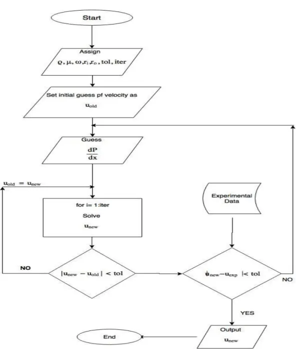
4.5.1 The proposed numerical method ... 39
4.5.2 Newton-Raphson method ... 41
4.5.3 Grid independent test ... 43
4.5.4 Comparison of both method ... 44
5. RESULTS AND DISCUSSION ... 46
5.1 Empirical Correlation for Determining Pressure Loss ... 46
5.2 Numerical Results of Mathematical Model ... 55
5.3 The Effects of Temperature and Rotation on Maximum Velocity in An Eccentric Annulus ... 67
vii
6. CONCLUSIONS ... 78
REFERENCES ... 81
APPENDICES ... 88
viii
ABBREVIATIONS AND NOMENCLATURE
𝑹𝑷𝑴 : Revolution Per Minute [T-1]
𝑹𝒆 : Reynolds Number 𝑻𝒂 : Taylor Number 𝑷𝒓 : Prandtl Number 𝒄𝒑 : Specific Heat [L2 Ɵ-1 T-2] 𝒌 : Thermal Conductivity [M L Ɵ-1 T-3] 𝒈 : Gravitational Acceleration [M L-2] 𝝎 : Pipe Rotation Speed [T-1]
𝑯 : Slot Height [L]
𝑫𝒊 : Inner Pipe Diameter [L]
𝑫𝒐 : Outer Pipe Diameter [L]
𝒕 : Time [T]
𝑷 : Pressure [M L-1 T-2]
𝒖, 𝒗, 𝒘 : Velocity Components in x,y,z Directions [L T-1]
𝝆 : Density [M L-3]
𝝉𝒊𝒋 : Stress Tensor [M L-1 T-2]
𝒖̅, 𝒗̅, 𝒘̅ : Mean Velocity Components [LT-1] 𝒖́,𝒗́, 𝒘́ : Fluctuating Velocity Components [L T-1] 𝒓𝒊 : Inner Pipe Radius [L]
𝒓𝒐 : Outer Pipe Radius [L]
ʋ : Kinematic Viscosity [L2 T-1]
𝜽 : Angle
𝝁 : Dynamic Viscosity [M L-1 T-1]
𝒍𝒎 : Mixing Length [L]
𝝁𝒕 : Turbulent Viscosity [M L-1 T-1]
: von Karman Constant
ix
LIST OF TABLES
Page Table 3.1 : Test parameter values during the experiments. ... 21 Table 3.2 : Test matrix for Newtonian fluid flow through the eccentric annulus. .... 32 Table 4.1 : Comparison of two numerıcal approaches. ... 44 Table 4.2 : Computational cost for two models used in the present study for
x
LIST OF FIGURES
Page
Figure 1.1 : Representation of annular flow in concentric annulus . ... 4
Figure 1.2 : Representation of an eccentric annulus . ... 7
Figure 2.1 : Representation of an equivalent slot for eccentric annulus . ... 19
Figure 3.1 : Flow loop used in this study.. ... 22
Figure 3.2 : Motor for pipe rotation and its control unit ... 23
Figure 3.3 : Inner pipe rotation rate control unit ... 24
Figure 3.4 : Test section and pressure transmitter. ... 25
Figure 3.5 : Flowmeter. ... 26
Figure 3.6 : Pump motor and butterfly valve.. ... 27
Figure 3.7 : Heater control unit and stirring motor.. ... 28
Figure 3.8 : Schematic diagram and picture of the flow loop.. ... 31
Figure 3.9 : Experimental setup verification by comparing experimental and calculated pressure drop... 33
Figure 4.1 : Flowchart of the computer code with proposed method.. ... 40
Figure 4.2 : Flowchart of the computer code with Newton’s approach.. ... 42
Figure 4.3 : Velocity profile for various grid number... 43
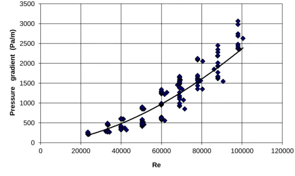
Figure 5.1 : Annular frictional pressure gradient (Pa/m) with respect to Reynolds number.. ... 49
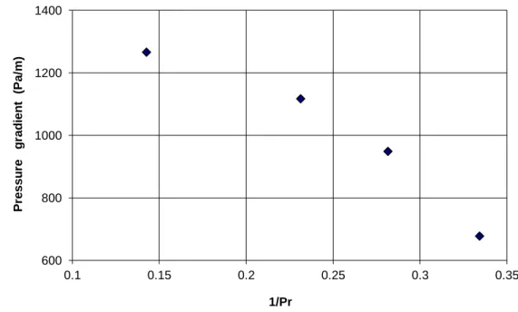
Figure 5.2 : Annular frictional pressure gradient (Pa/m) with respect to inverse of Prandtl number at Re = 60000 and Ta = 0.. ... 49
Figure 5.3 : Temperature effect on pressure gradient for different Reynolds number.. ... 50
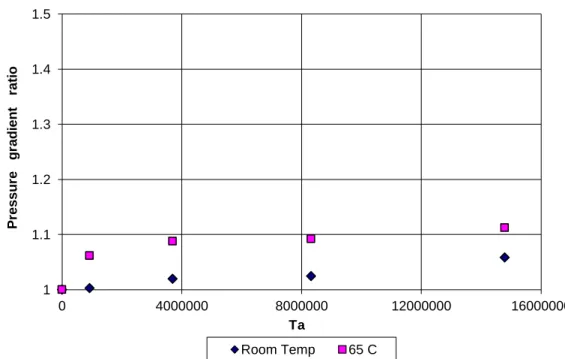
Figure 5.4 : Annular frictional pressure gradient ratio with respect to Taylor number at Re = 60,000 for different temperature values.. ... 50
Figure 5.5 : Annular frictional pressure gradient with respect to Reynolds number.. ... 51
Figure 5.6 : A0 with respect to Taylor number on semi-log scale.. ... 52
Figure 5.7 : B01 with respect to Prandtl number (Pr).. ... 53
Figure 5.8 : Comparison of experimental annular frictional pressure loss measurements with predicted results obtained by correlation.. ... 55
Figure 5.9 : For low fluid velocity, comparison of measured and predicted pressure gradient for room temperature without inner pipe rotation.. ... 57
Figure 5.10 : For high fluid velocity, comparison of measured and predicted pressure gradient for room temperature without inner pipe rotation.. ... 57
Figure 5.11 : For low fluid velocity, comparison of measured and predicted pressure gradient for room temperature and 30 rpm... 58
Figure 5.12 : For high fluid velocity, comparison of measured and predicted pressure gradient for room temperature and 30 rpm... 58
Figure 5.13 : For low fluid velocity, comparison of measured and predicted pressure gradient for room temperature and 60 rpm... 59
xi
Figure 5.14 : For high fluid velocity, comparison of measured and predicted
pressure gradient for room temperature and 60 rpm... 60
Figure 5.15 : For low fluid velocity, comparison of measured and predicted
pressure gradient for room temperature and 90 rpm... 60
Figure 5.16 : For high fluid velocity, comparison of measured and predicted
pressure gradient for room temperature and 90 rpm... 61
Figure 5.17 : For low fluid velocity, comparison of measured and predicted
pressure gradient for room temperature and 120 rpm... 61
Figure 5.18 : For high fluid velocity, comparison of measured and predicted
pressure gradient for room temperature and 120 rpm... 62
Figure 5.19 : Comparison of measured and predicted pressure gradient for room
temperature without inner pipe rotation at room temperature.. ... 63
Figure 5.20 : Comparison of measured and predicted pressure gradient for room
temperature without inner pipe rotation at 40 °C.. ... 63
Figure 5.21 : Comparison of measured and predicted pressure gradient for room
temperature without inner pipe rotation at 50 °C.. ... 64
Figure 5.22 : Comparison of measured and predicted pressure gradient for room
temperature without inner pipe rotation at 60 °C.. ... 64
Figure 5.23 : Comparison of measured and predicted pressure gradient for room
temperature and 30 rpm at 60 °C.. ... 65
Figure 5.24 : Comparison of measured and predicted pressure gradient for room
temperature and 60 rpm at 60 °C.. ... 66
Figure 5.25 : Comparison of measured and predicted pressure gradient for room
temperature and 90 rpm at 60 °C.. ... 66
Figure 5.26 : Comparison of measured and predicted pressure gradient for room
temperature and 120 rpm at 60 °C.. ... 67
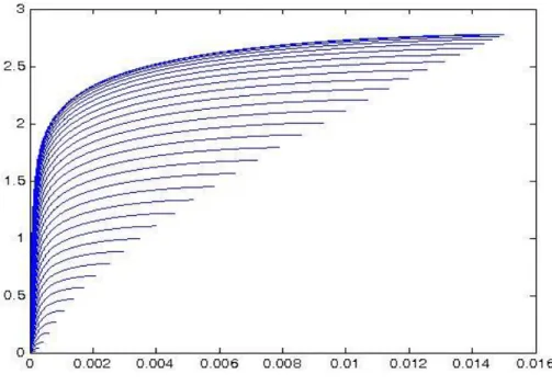
Figure 5.27 : Velocity profile for half-domain of the annulus at each angle at
dP/dL=1000 Pa/m, = 0 RPM, and T = 23 °C.. ... 68
Figure 5.28 : Velocity profile for half-domain of the annulus at each angle at
dP/dL=1000 Pa/m, = 30 RPM, and T = 23 °C.. ... 69
Figure 5.29 : Velocity profile for half-domain of the annulus at each angle at
dP/dL=1000 Pa/m, = 60 RPM, and T = 23 °C.. ... 69
Figure 5.30 : Velocity profile for half-domain of the annulus at each angle at
dP/dL=1000 Pa/m, = 90 RPM, and T = 23 °C.. ... 70
Figure 5.31 : Velocity profile for half-domain of the annulus at each angle at
dP/dL=1000 Pa/m, =120 RPM, and T = 23 °C.. ... 70
Figure 5.32 : Velocity profile for half-domain of the annulus at each angle at
dP/dL=1000 Pa/m, = 60 RPM, and T = 23 °C.. ... 71
Figure 5.33 : Velocity profile for half-domain of the annulus at each angle at
dP/dL=1000 Pa/m, = 60 RPM, and T = 40 °C.. ... 72
Figure 5.34 : Velocity profile for half-domain of the annulus at each angle at
dP/dL=1000 Pa/m, = 60 RPM, and T = 50 °C.. ... 72
Figure 5.35 : Velocity profile for half-domain of the annulus at each angle at
xii
Figure 5.36 : Maximum velocity profile for different inner pipe rotation at room
temperature for same flow rate.. ... 74
Figure 5.37 : Maximum velocity profile for different inner pipe rotation at 40 °C
for same flow rate.. ... 74
Figure 5.38 : Maximum velocity profile for different inner pipe rotation at 50 °C
for same flow rate.. ... 75
Figure 5.39 : Maximum velocity profile for different inner pipe rotation at 60 °C
for same flow rate.. ... 75
Figure 5.40 : Maximum velocity profile for different temperature without inner
xiii
MODELING AND EXPERIMENTAL STUDY OF TURBULENT NEWTONIAN FLUID IN FULLY ECCENTRIC ANNULUS CONSIDERING
TEMPERATURE AND PIPE ROTATION EFFECTS
SUMMARY
In this work, the effect of temperature on the pressure loss of Newtonian fluid in a fully eccentric annulus with pipe rotation is investigated. For this purpose, initially comprehensive experimental study has been conducted at Izmir Katip Celebi University (IKCU), Fluid Mechanics and Hydraulics Laboratory of Civil Engineering Department. Effect of temperature has been observed for flow velocities from 0.7 m/s to 3.4 m/s, for pipe rotations from 0 rpm to 120 rpm, and for temperatures is from 20 °C to 65 °C. The pressure loss within the test section is recorded. An increase in the liquid temperature results in a decrease in pressure gradient. On the other hand, the influence of temperature on pressure gradient becomes more significant, as the Reynolds number is raised. Variation of Taylor number causes negligible changes on frictional pressure losses for all temperature conditions considered. By using regression analysis of the dataset obtained from the experimental work, a simple empirical frictional pressure losses correlation taking into account of temperature effect is proposed. The proposed correlation could estimate the frictional pressure gradient within an error range of ± 5%.
Numerical methods frequently are used to solve turbulent flow problems due to the trouble in solving Navier-Stokes equations. Navier-Stokes equations including inner pipe rotation and temperature effects are solved via two different numerical techniques. Firstly, a developed numerical method presents the discretization of the equation with finite difference method and solved iteratively by fixing the nonlinear terms. Secondly, Newton-Raphson method is used to linearize the equation and then solve iteratively. The efficiency of the proposed scheme is compared with the
xiv
obtained solutions of the Newton-Raphson method. The proposed numerical method is computationally expensive, however, it may allow tackling the non-linearity of challenging problems in hydraulics. Moreover, a mechanistic model including proposed numerical method is developed in order to determine frictional pressure gradient for fully developed turbulent flow through fully eccentric horizontal annulus including pipe rotation and temperature. The computational frameworks are developed in MATLAB. A mathematical model is confirmed by the experimental study. Results show that computational fluid model is capable of estimating frictional pressure gradient with an error of less than 16.2%.
Keywords: frictional pressure loss, inner pipe rotation, temperature, correlation,
xv
SICAKLIK VE BORU DÖNME HIZI DİKKATE ALINARAK AYRI MERKEZLİ BORULAR ARASINDAN AKAN TÜRBÜLANSLI NEWTONIAN AKIŞKANIN MODELLENMESİ VE DENEYSEL
ÇALIŞMASI
ÖZET
Bu çalışmada iç içe geçmiş farklı merkezli (tam eksantrik) iki boru arasında akan Newton tipi akışkanlarda içteki borunun dönmesi durumunda sıcaklığın basınç farkına etkisi araştırılmıştır. Bu amaçla, İzmir Katip Çelebi Üniversitesi (İKÇÜ) İnşaat Mühendisliği Bölümü Akışkanlar Mekaniği ve Hidrolik Laboratuvarı’nda kapsamlı bir deneysel çalışma yapılmıştır. Sıcaklığın etkisi akışkan hızının 0.7 m/s ile 3.4 m/s arasında olduğu durumda, boru dönme hızının 0 ile 120 devir/dakika arasında olduğu durumda, ve 20 °C ile 65 °C sıcaklık aralığında gözlemlenmiştir. Deney düzeneğindeki basınç farkları kaydedilmiştir. Akışkan sıcaklığındaki artış basınç gradyeninde düşüşe yol açmaktadır. Bununla beraber, Reynolds Sayısı’nın artmasıyla birlikte sıcaklığın basınç gradyeni üzerindeki etkisi daha önemli hale gelmektedir. Diğer yandan ise, farklı Taylor Sayısı’nın deney aralığındaki bütün sıcaklık değerlerinde sürtünmeyle ilgili basınç kaybında ihmal edilebilir bir etkisi olduğu görülmüştür. Deneysel çalışmadan elde edilen verilerin regresyon analizi ile incelenmesi sonucunda, basınç kayıplarını sıcaklığın etkisini de dikkate alan basit bir ampirik denklem önerilmiştir. Önerilen denklem basınç gradyenini ±%5 hata payı ile tahmin edebilmektedir.
Navier-Stokes denklemlerinin çözümündeki zorluk sebebiyle, sayısal metotlar türbülanslı akış problemlerinde sıklıkla kullanılır. İçteki borunun dönmesi ve sıcaklık etkilerini içeren Navier-Stokes denklemleri iki farklı sayısal teknikle çözülmüştür. İlk olarak, önerilen sayısal metot, sonlu farklar metodu ile denklemin ayrıştırılmasını ve lineer olmayan terimlerin sabitlenerek iteratif olarak çözümlenmesini içerir.
xvi
İkincisi ise, Newton-Raphson metodu ile denklemin doğrusallaştırılması ve daha sonra iteratif olarak çözümünü içerir. Önerilen metodun verimliliği, Newton-Raphson metodundan elde edilen çözümler ile karşılaştırılmıştır. Önerilen sayısal metodun hesaplaması daha uzun sürmesine rağmen, hidrolikteki lineer olmayan meşakatli problemlerin üstesinden gelmeye yarayabilir. Ek olarak, boru dönmesini içeren iç içe geçmiş farklı merkezli borular arasından geçen tam gelişmiş türbülanslı akışlardaki sürtünmeye bağlu basınç farkını belirleyebilmek için önerilen sayısal metodu içeren bir mekanistik model geliştirilmiştir. Sayısal hesaplamalar MATLAB’ta geliştirilen kodlarla yapılmıştır. Yapılan sayısal hesaplamalar deneysel sonuçlarla teyit edilmiştir. Elde edilen sonuçlar, hesaplamalı akışkanlar modelinin sürtünmeye bağlı basınç farkını %16.2’den daha az bir hata ile tahmin edebildiğini göstermiştir.
Anahtar Kelimeler: basınç kaybı, içteki boru dönmesi, sıcaklık, korelasyon,
1
1. INTRODUCTION
1.1 Description of The Problem
Flow through annulus has many applications in civil engineering as well as other engineering branches such as petroleum engineering, mechanical engineering, etc. Some examples of these applications are cleaning of geothermal, oil and gas wells and heat exchanger, which is a device for transferring heat from one medium to another.
Among the annular flow used in technology, drilling oil wells is the most popular research area for the scientists. However, there are many crucial applications, which requires annular flow characteristics as well. For instance, processing industrial waste with slurries and suspensions, mass transport in blood through veins, and extrude plastics and polymers. The mathematical insight of those applications is far from trivial. Comprehensive understanding of the physical behavior of fluid flow requires in order getting accurate solutions. Just recently, it has been gradually available to predict all features of the annular flow including its affecting parameters such as flow velocity, rotating cylinder, eccentricity.
It is well known that temperature is a property that plays a significant role in changing liquid rheology. Increasing liquid temperature causes decreasing in viscosity. For instance, the viscosity of water at 62 °C is almost half of the viscosity of water at room temperature. It is common to assume that viscosity of liquids decreases linearly with increasing temperature. However, there are generally significant increases in the suspension viscosity, yield point and the gelling tension of the liquid due to accumulation when the temperature reach or pass the critical temperature of the liquid.This causes instability of the liquid. Therefore, the above assumption of viscosity relation with temperature for the non-Newtonian fluid may
2
not be valid. For this reason, it is necessary to conduct an intensive investigation of temperature effect on liquids.
Additional parameter on the fluid flow brings more complexity and requires experimental study in order to understand physical behavior of the corresponding parameters. Several factors can affect hydraulics and characteristics of the annular flow such as flow rate, flow regime, fluid rheology, geometry of annulus, inner pipe rotation, etc. Since annular flow characteristics gained attention, there has been a significant number of scientific studies for investigating those parameters effects on annular flow performance. However, there have been limited studies, which investigated the combined effect of those parameters while the fluid temperature varies.
The main objective of this present study is to better understand the effects of temperature on characteristics and hydraulics of the fully developed fluid flow in fully eccentric annuli including inner pipe rotation. The experimental study consists of Newtonian fluid –water- for turbulent flow regime. Experiments carried out with and without inner pipe rotation with varying fluid temperature at different flow rates. Accurate estimation of frictional pressure loss makes the determination of necessary hydraulic power available. In another word, the pump pressure is a function of frictional pressure loss. Therefore, determining pressure losses is essential to save energy, cost and also catastrophic events such as hole closure, tools loss etc. Therefore, pressure losses should be foreknown. The focus of this study is to determine pressure loss in an annulus. For that reason, frictional pressure loss along the test section of the flow loop was measured by using sensitive pressure transmitter for each experiment. Obtaining an empirical correlation for field use due to lack of time and instant measures is also necessary. In the present study, an empirical equation for determining pressure losses is presented and three dimensionless parameters that are effective on the pressure loss determination are used in the equation due to obtaining a general approach. For enhanced knowledge of the fully developed turbulent flow through annulus including inner pipe rotation and temperature variation effect, a mathematical model is also developed and solved numerically.
3
1.2 Literature Review
Determining frictional pressure loss has an importance of any design applications that require fluid flow. Misreading of pressure loss causes malfunction of the applications. For some cases, it can cause fatal incidents. Therefore, frictional pressure loss has been investigated and tried to develop general information by including additional parameters that have significant impact on pressure loss variation. In order to link the present study, previously published papers that are concerned about the hydraulics and characteristics of fluid flow through annular ducts are presented in this section. An interested scholar can be found a good start with this background.
1.2.1 Flow through concentric annuli
The start off the point of turbulence study is Leonardo Da Vinci’s drawings in the fifteenth century. Almost four hundred years later, the study of turbulence took again researchers attention. First, Boussinesq [1] proposed eddy viscosity idea and his hypothesis “turbulent stresses are linearly dependent to mean strain rates”. This hypothesis has been still used in most of the turbulence models.
Right after Boussinesq, Reynolds Osborne [2] conducted an experimental study. This study led him to identify the only physical parameter that helps to generalize the determination of the fluid in transition to turbulence.
According to Reynolds’ experiment, turbulent flow exists for the fluid flow through pipes at Reynolds number above 4000. However, Prengle and Rothfus [3] observed the first disturbance eddy starts at 2200 to 2300 Reynolds number for annular flow. Later, scientist and researchers have paid attention to annular flow and the first attempts to study annular flow was for concentric annulus due to its simplicity. The representation of concentric annulus can be seen Figure 1.1.
4
Figure 1.1 : Representation of annular flow in concentric annulus
Bird and Fredrickson [4] proposed an empirical model for predicting volumetric flow rate and frictional pressure loss of non-Newtonian fluids through the concentric annulus.
Rofthus et al. [5] proposed a model in order to estimate velocity profile for turbulent flow of water through concentric annuli. He conducted experiments on different radius ratio and compared his model with his experimental data. He concluded that his proposed model establish reasonably good annular velocity profile by comparing annuli.
Skelland [6] proposed an empirical solution for Bingham plastic fluid flow through the concentric annulus. Although he presented an exact solution of volumetric flow rate, the equation is big and not practical to use in the field.
Quarmby {7] conducted an experimental study on fully developed turbulent flow in concentric annuli. He concluded that the radius of maximum velocity decreases with Reynolds number below 50,000. On the other hand, it is independent of radius ratio above Re = 50,000.
A year later, Klump and Kwasnoski [8] developed an eddy diffusivity model in order to predict velocity distribution for the air of turbulent flow through concentric annuli.
5
They compared their model with previous experimental studies and models. They obtained good agreement with them, although their models are simpler than previous models.
Meter and Bird [9] used previous experimental results from literature and proposed a friction factor based on Reynolds number by using Prandtl mixing length. They stated that mixing length friction factor expression gives better prediction than hydraulic radius procedure.
Hanks and Larsen [10] presented an algebraic solution for volumetric flow rate and pressure drop of power-law fluid in laminar regime through the concentric annulus. They stated that their mathematical model is valid for all flow behavior index and annulus aspect ratio.
Later, Leung [11] figured out that previous models of friction factors prediction scatter away from accurate results for small gaps. His empirical equation gives the friction factor of turbulent flow at Reynolds number above 7,000 within 5 percent error margin.
Nouri et al. [12] conducted an experimental study on Newtonian and non-Newtonian fluids in both concentric and eccentric annulus. They concluded that the friction factor coefficient variation with Reynolds number implies if there is concentric annular flow rather than smooth pipe flow, the flow resistance increases around 8% in concentric annuli.
Gucuyener and Mehmetoğlu [13] conducted a study to develop a simple mathematical model which has an analytical solution to find volumetric flow rate of yield pseudo-plastic fluids flow through the concentric annulus.
Escudier and Gouldson [14] conducted an experimental study in order to understand the effect of inner pipe rotation on pressure drop in the concentric annulus. They concluded that the inner pipe rotation is negligible on the pressure loss when the flow is turbulent for both Newtonian and non-Newtonian fluids. However, inner pipe rotation is moderately effective when the flow is in laminar regime.
Gucuyener and Mehmetoğlu [15] conducted another study on yield pseudo-plastic fluids flow characterization in the concentric annulus. They concluded that transition
6
in flow regime is very sensitive to the geometry of the conduits and rheology of the fluids.
Filip and David [16] analyzed non-Newtonian fluid flow through concentric annulus including the effects of geometry, kinematic and rheologic behavior of fluids while the inner pipe moving axially. They proposed a semi-analytical model to predict volumetric flow rate. They compared their result with Robertson–Stiff model and obtained relatively good results.
Enhancing computer technology enabled Chung and Sung [17] investigation of the effect of inner wall rotation on the velocity profile with LES (Large Eddy Simulation) method. Their simulation emphasized that the mean velocity is getting lower slowly when the flow is approaching the wall while the inner pipe rotates. Sorgun and Ozbayoglu [18] proposed a mechanistic model in order to have a general solution for estimating the friction factor of Newtonian turbulent flow through concentric annuli. The results showed that proposed model can predict within 10% error margin.
Kelessidis et al. [19] compared their experimental data for laminar, transition, and turbulent flow through concentric annulus with the previously proposed models to determine pressure losses. They concluded that API correlations obtain much higher pressure drop than their indicated data when in transition to the turbulent regime. They solved the problem by adding a correction factor.
As it can be analyzed that the application of fluid flow through concentric annulus has been studied widely in analytically, experimentally and computationally. Annular flow in the concentric annulus is a preliminary study for enhanced complex geometry or any additional parameters that brings complexity to solution of fluid flow problem in the annulus. Due to its symmetric geometry, authors prefer to approach concentric annulus first in order to step ahead to more complex geometries. Those mentioned studies cover most of the attempts to understand the annular flow in the concentric annulus.
7
1.2.2 Flow through eccentric annuli
In applications of fluid flow through the annulus, the geometry is rarely concentric. Most of them lose the alignment of the center body and become eccentric due to gravity, roughness etc. The representation of eccentric annulus can be seen in Figure 1.2. Fluid flow in an eccentric annulus has been taken great attention of researchers over the years. The effect of eccentricity on velocity profile and frictional pressure loss was studied by following researchers.
Figure 1.2 : Representation of eccentric annulus
Deissler [20] investigated an analytical model for turbulent heat and mass transfer in smooth tubes. He accounted the effect of kinematic viscosity in the region close to the wall and he obtained good agreement with experimental results. After his previous work, Deissler and Taylor [21] conducted an analytical study to describe the velocity profile of turbulent flow through eccentric annular geometries.
8
Wolffe and Clump [22] conducted an experimental study on determining velocity lines and locus of maximum velocity for turbulent flow of air. They compared their experimental results with the calculated solution of Navier-Stokes equation with Heyda’s assumption [23] for analytical solution of laminar flow in annuli containing eccentricity. Wolffe and Clump also compared theirs with Deissler and Taylor’s study [21]. They concluded that their study well matches with the previous analytical solution of Navier Stokes equation under certain assumptions.
Johnson and Sparrow [24, 25] conducted experimental work on turbulent flow in the eccentric annulus and they reported that circumferential pressure gradient is quite larger than that for concentric annulus. Also, they observed that friction factor decreases with increasing eccentricity.
Rehme [26] proposed a correlation of friction factor prediction for turbulent flow in channels with non-circular cross-sections. He concluded that this prediction method is better than all previous attempts and it can be used on other shapes of channels such as eccentric annulus.
Kacker [27] conducted an experimental study of fully turbulent flow in the circular pipe containing one or two eccentrically located rods. He developed a correlation to estimate friction factor. The correlation predicts the experimental data with 2% error margin for both one and two rods geometries.
Usui and Tsuruta [28] analyzed the equation of motion for fully turbulent flow in an eccentric annulus with using Kirchoff transformation. They explained the dependence of eccentricity on friction factor at high Reynolds number range.
Tosun [29] proposed an approximate solution axial laminar flow through the eccentric annulus and he compared his results with previously published experimental works. An approximate solution is relatively good agreement with the data in the literature. He and his group [30, 31] expanded the study for non-Newtonian fluids applying on Power law, Bingham plastic and Sutterby models. Those studies were concluded that proposed approximate solution well matches with previous experimental studies.
9
Ogino et al. [32] also investigated momentum equation for fully developed turbulent flow in the eccentric annulus. They used bipolar coordinate transform in order to model eccentric annulus geometry.
Haciislamoglu and Langlinais [33] investigated the effect of eccentricity on frictional pressure losses without inner pipe rotation and obtained pressure losses reduction as much as 60%.
Nouri et al. [12] conducted an experimental study on Newtonian and non-Newtonian fluids in both concentric and eccentric annulus. They concluded that the flow resistance decreases as the eccentricity is increased when it is compared with smooth pipe flow.
One year later, Nouri and Whitelaw [34] introduced rotational effect in the same study and their results showed that the effect of rotation on frictional pressure losses decreases with increase in Reynolds number after the flow is in transition. Decreasing of rotational effect on frictional pressure losses continues until they are same as without rotation case. Numerical and analytical approaches have been done for modeling turbulent flow.
The study of Haciislamoglu and Langlinais [33] was conducted under laminar flow regime. Corresponding to this study, Erge et al. [35] conducted another experimental study of turbulent flow in the eccentric annulus. They concluded that eccentricity significantly reduces the frictional pressure loss in turbulent flow as well.
Erge et al. [36] conducted an experimental, analytical and numerical study of the effect of eccentricity on frictional pressure loss. They concluded that frictional pressure loss in fully eccentric annulus has up to 50% discrepancy than the results which is calculated with Narrow Slot approach.
Recently, Rushd et al. [37] investigated eccentricity, roughness and rotation effects on frictional pressure loss. They conducted an experimental study and developed a CFD model in ANSYS validated by experimental results. Their CFD analysis showed that effect of roughness and eccentricity are more prominent than the effect of inner pipe rotation.
10
1.2.3 Flow through annuli including pipe rotation effect
Coleman and Nole [38] developed an expression for determining axial pressure drop, discharge rate and angular velocity for incompressible fluid flow through concentric annulus with inner pipe rotation. Their study is one of the classical studies for helical flow.
Walker and Al-Rawi [39] conducted an experimental study in order to validate the model proposed by Coleman and Noll [38] and also Fredrickson and Bird [4] for laminar helical flow to predict pressure drop with inner pipe rotation. They observed that decrease in pressure drop while increasing inner pipe rotation. The result shows similarity with the previous study.
Luo and Peden [40] proposed a method of solving the dimensionless equations, which were derived for obtaining an analytical solution of helical flow in the concentric annulus. Those dimensionless equations consist of three dimensionless parameters such as inner pipe rotation rate, ratio of inner and outer pipe diameter and fluid behavior index.
Delwiche et al. [41] studied theoretical of rotation effects in the eccentric annulus with comparing field study. They concluded that inner pipe rotation increases frictional pressure loss up to 100% at 500 RPM.
Marken et al. [42] investigated combination effects of eccentricity, inner pipe motion and fluid temperature on flow regime which contributes to determine pressure losses. They concluded that combined effect of those three parameters makes a significant change in pressure losses. Increasing inner pipe rotation increases pressure losses. However, the variation of fluid temperature couldn’t be determined because of complexity and not easily implemented into the classical models.
Cui and Liu [43] solved numerically the governing equations of the helical flow of the non-Newtonian fluid in eccentric annuli by using the finite difference method. Numerically calculated flow rates are compared with the flow rates that measured in the experiments.
McCann et al. [44] experimentally investigated pipe rotation and eccentricity effect on pressure losses of non-Newtonian fluid flow in the annulus. They proposed a
11
simple correlation for estimating pressure losses for fluid flow through concentric annulus including inner pipe rotation and eccentric annulus without inner pipe rotation. They observed that increasing inner pipe rotation increases pressure losses in turbulent flow and decreases in laminar flow.
Hansen et al. [45] asserted a hydraulic model that included the effect of eccentricity, pipe rotation, and fluid rheology. Furthermore, they performed an experimental study for providing data in order to confirm and complement the pressure loss model. Escudier et al. [46] conducted an experimental and computational study of the fully developed laminar flow of Newtonian fluid through eccentric annulus including inner pipe rotation. They transformed N-S equations from rectangular coordinate to non-orthogonal coordinate and solved it numerically. According to their results, they reported that increase in inner pipe rotation rate causes increases in frictional pressure loss.
Wan et al [47] investigated inner pipe rotation effect on Newtonian and non-Newtonian fluid flow in eccentric annuli by using numerical SIMPLE approach. They concluded that frictional pressure loss always increase with pipe rotation rate when the eccentricity is high (greater than 0.9)
Ooms and Kampman-Reinhartz [48] studied analytical, numerical and experimental study of influencing inner pipe rotation and eccentricity of Newtonian fluid flow through the annulus. In this study, they reported that there are insignificant effects of inner pipe rotation at high flow rates. Domination of inertial effect on rotation effect is given as an explanation of the insignificant effect of inner pipe rotation.
Fang and Manglik [49] conducted a comprehensive theoretical study of effects of inner pipe rotation, radius ratio and eccentricity on frictional pressure loss of Newtonian fluid. They employed the stream function and vorticity formulation for fully developed laminar flow and solved it numerically. According to their result, inner pipe rotation increases axial pressure drop. This effect is more pronounced at medium eccentricity (between 0.5 and 0.6).
Diaz et al. [50] conducted an experimental study and proposed a new model to estimate frictional pressure losses with pipe rotation in the concentric annulus. They
12
extended Tao and Donovan’s method [51] by applying narrow slot approach. They concluded that their model comparison with experimental results shows good agreement.
Hemphill and Ravi [52, 53] developed a model with using advanced engineering approach by coupling axial and radial velocities. They concluded that pipe rotation can lower the pressure drop. However, pipe rotation can raise pressure drop after a certain rate. Furthermore, they stated that changing pipe radius ratio causes a change in pressure drop as well.
Alizadehdakhel et al. [54] determined pressure drop by using the ANN and computational fluid dynamics (CFD) and compared the performance. They stated the CFD has better result than ANN for their model.
Ahmed et al. [55] investigated the effect of pipe rotation on equivalent circulation density. Results indicated that pressure loss ratio is affected by various parameters including pipe rotation speed, pipe eccentricity, fluid properties, diameter ratio and flow regime.
Neto et al. [56] simulated rotating and non-rotating turbulent flows of Newtonian fluids in concentric and eccentric annular sections using computational fluid dynamics (CFD) with different turbulence models based on the RANS approach. Sorgun et al. [57] studied and developed a mathematical model to predict flow characteristics of Newtonian fluids in a concentric annulus. To obtain velocity field, Navier-Stokes equations are numerically solved using the finite differences techniques.
Furthermore, Bicalho et al. [58] concluded from his experimental study that annular pressure drop is effected by CG concentration, fluid flow rate, eccentricity and inner pipe rotation.
Erge et al [59] conducted another CFD analysis for estimating pressure losses in an eccentric annulus including inner pipe rotation. They obtained good agreement with their experimental data and the empirical results. ANN has been used widely to solve complicated fluid mechanics problems.
13
With developing new technologies enhance us to use computer intelligence such as artificial neural networks (ANN) and any other computational applications. Rushd et al [37] implemented a CFD model in ANSYS CFX in order to investigate the effect of eccentricity, rotational speed, and equivalent hydrodynamic roughness. They obtained the results within 30% error margin.
Rooki and Rakhshkhorshid [60] estimated the pressure loss of drilling fluids inside the horizontal annulus using the ANN. They obtained their prediction within 5.93% error margin.
Additional to his previous study, Rooki [61] investigated the prediction capability of GRNN (General Regression Neural Network) by comparing his experimental data. The study was indicated that GRNN can predict pressure losses with high accuracy.
1.2.4 Flow through annuli including temperature effect
There are many parameters that incorporate to change annular frictional pressure losses such as flow rate, fluid properties (density and viscosity), annulus geometry, flow regime, pipe rotation, and pipe eccentricity as stated previously. In addition to all those parameters, temperature also has a significant role in determining annular frictional pressure losses. If the ambient temperature of the fluid is changed, the rheological properties of the fluid and flow performances vary. In many cases, significant differences are observed when theoretical calculations and measurements for pressure losses are compared. There has been some attempt to investigate temperature effects on flow through ducts.
Syrjala [62] conducted a study to provide accurate heat transfer prediction for non-Newtonian fluid flow through the rectangular duct by finite element method. On the other hand, Naccache and Mendes [63] solved the mass, momentum and energy equations for the same problem as Syrjala [51] but using finite volume technique. Then, Moraga et al. [64] investigated heat transfer for annular flow by using finite volume technique as well.
Peixinho et al. [65] experimentally investigated temperature effect on dynamics of the flow in the circular pipe for transition regime. Farias et al. [66] conducted another
14
experimental study of heat transfer coefficient of flow through the concentric pipe in laminar regime.
Sheela-Francisca et al. [67] developed a semi-analytical solution for temperature distribution through a channel under the assumption of Coutte-Poiseuille flow in laminar flow regime. As well as experimental study of heat transfer analysis for flows through ducts,
Lian-Cun et al. [68], Carmona et al [69], Prasad et al. [70], Li et al. [71] studied theoretical phenomena of the heat transfer through ducts and developed CFD solutions. Pinho and Coelho [72] and Yavuz et al. [73] studied analytical solution of heat transfer in the concentric annulus.
Han et al. [74] did closer attempt to the present work. They investigated temperature effect including rotation effect in eccentric annulus both experimentally and numerically. However, their results are limited to Newtonian laminar flow.
It can be realized that adding the additional parameters to fluid flow makes the problem more challenging. Enhancing information about annular flow leads the researcher to investigate effects of substantial parameters. In this study, turbulence Newtonian fluid flow through fully eccentric annulus including inner pipe rotation and temperature effects has studied both experimentally and computationally. When all previous attempts are analyzed, it has been seen that the solution of the problem considering all those combined effects is still a gap in the literature.
1.3 Scope of The Present Study
In the present study, the temperature effects on annular frictional pressure losses with inner pipe rotation in a fully eccentric annulus are investigated experimentally. Experiments were done in the flow loop constructed in IKCU Civil Engineering Department’s Hydraulics and Fluid Mechanics Laboratory. Firstly, experimental results were gathered and compared how the flow hydraulics and characteristics change with various flow variables such as axial flow rate, inner pipe rotation rate. Then, the effects of those variables on frictional pressure loss were again observed when the temperature of the fluid differs. By using regression analysis of the dataset
15
obtained from the experimental work, a simple empirical frictional pressure losses correlation taking into account of temperature effect was proposed due to ease of determining pressure loss for field use. Moreover, the mathematical model of momentum equation for fully developed turbulent flow in fully eccentric annuli including the effects of temperature and inner pipe rotation was developed in order to have a general solution.
Within this dissertation, one can find the theory of fully developed turbulent flow through eccentric annulus including inner pipe rotation in Chapter 2. Experimental setup and process can be found at Chapter 3 in details. In Chapter 4, derivation of mathematical modeling of momentum equation of fully turbulent flow with or without inner pipe rotation in Cartesian Coordinates can be found. Evaluation of the data from experiments, mechanistic models, and the empirical equation can be found in Chapter 5.
16
2. THEORY
2.1 Basic Equations For Turbulent Pipe Flow
This part of the present study is aimed to present governing equations of motion for turbulent flow. The fundamental mathematical model of fluid flow motion is given by the Navier Stokes equations in closed form as;
Continuity Equation 0 i i u t x (1) Momentum Equation (2)
In the closed form of Navier-Stokes equations shown above, velocity term consists of mean velocity component and fluctuating component for turbulent flow case. Therefore, velocity term in these equations should be written in the form of;
u u u (3)
where u represents mean velocity component and u represents fluctuating component of the fluid flow.
As an old-fashioned way for mathematical modeling of turbulent flow is modifying Navier-Stokes equations by satisfying mean value parameters such as u and p and approaching to the real value of velocity and pressure. However, in Reynolds Averaged Navier-Stokes equations (RANS), the modified NS equations for the mean values should be obtained by taking mean values of NS equations in order to get
j j ij i j i j i u u P u g t x x x
17
Averaged NS equations. Replacing all variables in momentum equation with their mean and fluctuating component, also taking their time average gives the well-known RANS equation as in closed form of;
(4)
After this point mean velocity (e.g. u ) replace the same latter without bar (e.g. u ) for simplicity. In Cartesian coordinate, Bird et al. [78] expanded the closed form of equation of motion for turbulent flow including pipe rotation as;
For x-momentum equation;
(5)
For y-momentum equation;
(6)
For z-momentum equation;
(7)
j i j i j ij j i j i u P u u u u g t x x x
2
2 xx yx zx x u u u u u v w t x y z u u v u w P g y x x y z x y z
2
xy yy zy y v v v v u v w t x y z v u v v w P g y x y z x y z
2
xz yz zz z w w w w u v w t x y z w u w v w P g z x y z x y z 18
2.2 Fluid Properties
For Newtonian fluids, momentum transport term in general form can be expressed as; 2 3 j i k ij ij j i k u u u x x x (8)
where ijis Kronecker delta.
yx
represents the y component of the stress acting on the surface whose outward normal is located in the positive x-direction. For Newtonian fluids, the constitutive equation of stress tensor is;
(9)
2.3 Geometry and Narrow Slot Approach
In the present study, experiments were conducted for flow in the fully eccentric annulus. Therefore, the height of the slot should be determined according to the eccentric annulus. Iyoho and Azar [79] proposed a model for determining the height of eccentric annulus. Unlike concentric annulus, they stated that the height of eccentric annulus varies with respect to pipe angle.
It is hard to display and understand flow behavior in an eccentric annulus. Therefore, Vaughn [80] approached the flow through an eccentric annulus as slot flow. The equivalent slot representation of eccentric annulus is slightly different when it is compared with concentric annulus due to variable slot height. The slot equivalents for both concentric and eccentric annulus can be displayed in Figure 2.1.
yx v u x y
19
Figure 2.1 : Representation of equivalent slot for eccentric annulus
This approach overcomes the complexity of using bipolar coordinates, conformal transformation, and iterative computations. Iyaho and Azar [79] used Vaughn’s [80] slot flow approach without his simplifying assumptions and obtained good accuracy with previous investigator’s analytical studies in which complex coordinates or transformations were used. Therefore, Vaughn’s approach has been used in the present study. The detail of narrow slot approach has been presented in the Appendix B. The final formula to determine the slot height for fully eccentric annulus is;
(10) After the numerical solution of the momentum equation, u y( , ) can be found. However, the data of the experiment only provides the flow rate and therefore average annular fluid velocity. The relation between average annular velocity and point velocity at coordinates ( , )y can be formulated as;
2 2 2 1 Sin Cos 2 o o i i H r r r r 20 ( , ) ( , ) a a emp u y u y u u (11) ( , ) a emp u y u
is a dimensionless ratio and the value can be obtained from
experimental study data of Iyaho and Azar [79]. The angle, which frictional pressure losses measurements are taken, is about 90° as it can be seen in Figure 3.3. ( , ) a emp u y u
value for 90° is 0.67 according to Iyaho and Azar’s [79] study. In
the present study, numerical solution of momentum equation gives point velocity of the fluid at coordinates ( , )y . However, one can obtain average annular velocity by using flow rate measured from the flowmeter. Therefore, it is needed to divide point velocity to ( , ) a emp u y u
ratio in order to obtain average annular fluid velocity.
Taking the angle as 90° simplifies the slot height formula as;
22 1
2 o o i i
21
3. EXPERIMENTAL STUDY
Experiments of Newtonian fluid flow through fully eccentric annulus including inner pipe rotation and temperature effects are conducted at Izmir Katip Celebi University. One can find detailed experimental setup and procedure in the following section.
3.1 Experimental Setup
A flow loop was constructed at Izmir Katip Celebi University, Fluid Mechanics & Hydraulics Laboratory. The specifications of the experimental setup are given in Table 3.1.
Table 3.1 : Test parameter values during the experiments
Experiment Specifications Values
Inner – Outer Pipe Diameter 40 – 80 mm
Flow Loop length 10 m
Flow velocity 0.7 – 3.6 m/s
Temperature 20 - 60 °C
Inner pipe rotation speed 0 – 120 rpm
Flow loop, 10 m long, has been formed from 80 mm outer pipe and 40 mm inner pipe. Inner pipe has been fixed concentrically at both ends and full eccentric annulus has been obtained at the test section due to gravity.
The flowmeter was assembled 210 cm away from the pump in order to prevent misreading due to pump wake. The diameter of the flowmeter is 125 mm. Due to
22
contraction and end effects, a 70 cm extension pipe was placed after flowmeter. The flowmeter has 0.15% – 0.55% uncertainty of reading the flow rate till the flow rate and temperature reaches 700 m3/h and 80 °C, respectively. ETRANS-DP pressure transmitter was used to measure pressure losses and the uncertainty of pressure transmitter in full scale is below 0.07% for temperature from 0°C to 70°C. Pressure transmitter has been placed 7 m away from the entrance in order to maintain fully developed flow at the test section. The test section is 0.5 m in length. The data from flowmeter and pressure transmitter has been taken by DT80 Data logger to electronic media for every 5 seconds during experiments. Pictures of the flow loop are shown in figures below.
23
An electrical motor unit has been connected to the flow loop end, which is shown in Figure 3.2. The motor has been fixed to the system with a shaft that can avoid leaking as well. This shaft is directly connected to inner pipe which is stabilized concentrically at that point in order to avoid any harm to the AC motor.
24
AC motor has the capability of provide maximum 1382 rpm with the frequency of 50 Hz with spending 2.2 kW power. Due to fully eccentric nature of the system throughout most of the flow loop, it causes cracks on the plexiglass tube at high inner pipe rotation. Therefore, leakage of the flow loop arises and that causes misreading of pressure gradient. For this reason, a digital controller of the inner pipe rotation rate has been used and it is shown in Figure 3.3.
25
The test section is 50 cm long and the angle of both orifice with respect to center of the outer pipe has been tried to fix at same value. Moreover, both orifice have small device in which the closure member of pressure transmitter is either rotated or moved transversely or longitudinally in the waterway so as to control or stop leakage.
Moreover, the side of these orifices have been applied special thermal silicon
elastomer in order to avoid leakage at higher fluid temperature. Figure 3.4 shows the test section and the position of the orifices.
26
ETRANS-M 210 electromagnetic flowmeter has been used for determining flow rate in the system. It can read maximum 100 m3/h flow rate. Due to brittle nature of the plexiglass, it has been avoided to allow the flow rate over 32 m3/h. The flowmeter can read truly when it is fully loaded and away from both pump effect and end effect. Due to these reasons, the flowmeter has been assembled 2.25 m away from the pump and 1 m away from the beginning section of the flowloop.
27
A 10-HP centrifugal pump has been used with butterfly type control valve in order to provide controlled circulation flow rate in the flow loop. Pump has occasionally stroke and change the flow rate because of mechanical malfunction of the valve. Flow rate has to be fixed then wait for a period in order to obtain straight and constant flow. Butterfly valve can resist up to 75 °C, it losses its property and lead to uncontrollable flowrate above this temperature.
28
Same AC motor as inner pipe rotation has been used for stirring fluid in the feeding tank. Stirring the fluid in the feeding tank is necessary in order to have a homogenous temperature in the system. Also, heater unit has been controlled by digitally and the system shuts down itself when the demand fluid temperature is reached. Continuously heating fluid inside tank causes shortcut and loss of tools. Therefore, controlling the temperature digitally and stirring the fluid while heating the fluid is important. Figure 3.7 shows the location of the stirring motor and heating controller unit on the feeding tank.
29
In the test system, the input and output effects were taken into account and the pressure loss measurements were made using pressure transmitters. The pressure gradient was defined as the function of temperature and other parameters. A Newtonian fluid, water, has been used in the experiment. The experiments were repeated at least 2 times.
When the feeding tank is filled with water, the thermostatic heater is turned on in order to increase the temperature of the water in the feeding tank. The fluid used in the experiment is returned to the fluid feeding tank, which is kept at a constant temperature between the pipes at a constant temperature. Furthermore, 230 V DV motor on the tank for stirring the water and the digital controller of the heater is switched on in order to make the water to reach necessary temperature. As soon as the temperature of the water is read as the desired value by using a thermocouple, the heater is automatically turned off. In contrast, the heater is automatically turned on when the temperature of the water dropped below the desired value. For this reason, the temperature of the water remains constant during experiments. After the desired temperature of the water is obtained, the butterfly valve is opened to release the fluid to the system.
When the system is completely filled with water, a motor pump that has 10 HP is switched on. To make rotation pipes ready for rotating, 230 V DC motor is turned on. Also, a 0-50V / 0-20 A switching power supply is turned on in order to switch on ETRANS-M 210 electromagnetic flowmeter and ETRANS-DP pressure transmitter that are connected to a desktop PC via a DT80 data logger. Water is arranged to desired flow value in the system by using the butterfly valve and flowmeter. Then, the digital controller of the inner pipe rotation motor is set to the desired value of rotational speed. The water is let to run within the system for a certain time till the flow becomes steady and isothermal in the entire system. As soon as the readings are
30
stable, experiment data is started to record. Input parameters are changed accordingly and repeated previous steps until data is collected for all desired parameters.
3.2 Experimental Test Procedure
A Newtonian fluid, water, has been used in the experiment. Inner pipe has been fixed concentrically at both ends and full eccentric annulus has been obtained at the test section. Schematic diagram and picture of the flow loop are shown in Figure 3.8. The following procedure is used for the tests:
• Fill the feeding tank with water
• Start the thermostatic heater for increasing the temperature of the fluid in the feeding tank
• Set the heater to desired value by digital controller
• Start 230 V DC motor on the tank for stirring the fluid in the tank in order to have homogenous temperature distribution in the fluid
• Open the butterfly valve to release the fluid to the system • Start 10 HP pump
• Wait till the flow is steady and isothermal in the entire system • Set flow rate to desired value
• Start 230 V DC motor for rotating inner pipe • Set inner pipe rotation rate to desired value • Start data acquisition system
• Start 0-50V / 0-20 A switching power supply
• Connect ETRANS-M 210 electromagnetic flowmeter to the power supply • Connect ETRANS-DP pressure transmitter to the power supply
• Start recording data
• As soon as the readings are stable, change one of the input parameters (flow rate, inner pipe rotation rate, temperature)
31
• Repeat the previous step until data is collected for all desired parameters. • Stop recording data
• Disconnect flowmeter and pressure transmitter • Stop power supply
• Stop the motor for inner pipe rotation • Stop the pump
• Stop the motor for stirring the fluid inside the feeding tank • Stop the heater
32
3.3 Experimental Test Matrix and Validation
The test matrix for the experiment of fully developed turbulent flow of Newtonian fluid including temperature and inner pipe rotation through fully eccentric annulus is presented in Table 3.2.
Table 3.2 : Test matrix for Newtonian fluid flow through eccentric annulus
Flow Rate (m3/h)
Inner Pipe Rotation Rate (RPM) Fluid Temperature (°C) 7 m3/h 0 23 40 50 60 30 23 40 50 60 60 23 40 50 60 90 23 40 50 60 120 23 40 50 60 10 m3/h 0 23 40 50 60 30 23 40 50 60 60 23 40 50 60 90 23 40 50 60 120 23 40 50 60 13 m3/h 0 23 40 50 60 30 23 40 50 60 60 23 40 50 60 90 23 40 50 60 120 23 40 50 60 16 m3/h 0 23 40 50 60 30 23 40 50 60 60 23 40 50 60 90 23 40 50 60 120 23 40 50 60 19 m3/h 0 23 40 50 60 30 23 40 50 60 60 23 40 50 60 90 23 40 50 60 120 23 40 50 60 22 m3/h 0 23 40 50 60 30 23 40 50 60 60 23 40 50 60 90 23 40 50 60 120 23 40 50 60
33 25 m3/h 0 23 40 50 60 30 23 40 50 60 60 23 40 50 60 90 23 40 50 60 120 23 40 50 60 28 m3/h 0 23 40 50 60 30 23 40 50 60 60 23 40 50 60 90 23 40 50 60 120 23 40 50 60 31 m3/h 0 23 40 50 60 30 23 40 50 60 60 23 40 50 60 90 23 40 50 60 120 23 40 50 60
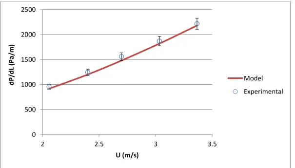
It is necessary to calibrate the experimental study for obtaining correct experimental data. For this purpose, the flow loop were run for water at room temperature and without inner pipe rotation for various flow rates. Pressure drop values are recorded and compare with calculated theoretical values for smooth pipe. Figure 3.9 shows that the measured and calculated pressure drop values are in good agreement.
Figure 3.9 : Experimental setup verification by comparing experimental and
calculated pressure drop
0 500 1000 1500 2000 2500 3000 0 5 10 15 20 25 30 35 P re ssu re Gr ad ie n t (P a/ m ) Flow Rate (m3/h) Theoretical Experimental