İZMİR KATİP ÇELEBİ UNIVERSITY «GRADUATE SCHOOL OF SCIENCE AND ENGINEERING
Computer Based X-Ray Imaging Device Design Alternative Using Consumer Electronic Components
M.Sc. Thesis
Alpman MANALP
Department of Biomedical Technologies
Thesis Advisor: Assistant Prof. Dr. Yalçın İŞLER
İZMİR KATİP ÇELEBİ UNIVERSITY « GRADUATE SCHOOL OF SCIENCE AND ENGINEERING
Computer Based X-Ray Imaging Device Design Alternative Using Consumer Electronic Components
M.Sc. Thesis
Alpman MANALP (Y13101005)
Department of Biomedical Technologies
Supervisor: Ast. Prof. Dr. Yalçın İŞLER
03 EKİM 2017
İZMİR KATİP ÇELEBİ ÜNİVERSİTESİ « FEN BİLİMLERİ ENSTİTÜSÜ
Tüketici Elektroniği Bileşenleri Kullanılarak Alternatif Bir Bilgisayar Tabanlı X-Işını Görüntüleme Cihazı Tasarımı
YÜKSEK LİSANS TEZİ Alpman Manalp
(Y130101005)
Biyomedikal Teknolojileri Ana Bilim Dalı
v
Jury Members: Assistant Prof. Dr. Ahmet GÖKÇEN ... İskenderun Technical University
Alpman Manalp, a M.Sc. student of IKCU Institute of Biomedical Technologies student ID Y13101005, successfully defended the thesis entitled “Computer Based X-Ray Imaging Device Design Alternative Using Consumer Electronic
Components”, which he prepared after fulfilling the requirements specified in the associated legislations, before the jury whose signatures are below.
Date of Submission : 05 September 2017 Date of Defense : 03 October 2017
Thesis Advisor: Assistant Prof. Dr. Yalçın İŞLER ... İzmir Katip Çelebi University
Assistant Prof. Dr. Rukiye UZUN ... Bülent Ecevit University
vii PREFACE
Dedicated with extreme affection and gratitude to my wife Dr. Funda Manalp and my research supervisor Ast. Prof. Dr. Yalçın İşler.
ix TABLE OF CONTENTS Page PREFACE ... vii TABLE OF CONTENTS ... ix ABBREVIATIONS ... xi
LIST OF FIGURES ... xiii
LIST OF TABLES ... xv
COMPUTER BASED X-RAY IMAGING DEVICE DESIGN ALTERNATIVE USING CONSUMER ELECTRONIC COMPONENTS ... xvii
1 INTRODUCTION ... 1
1.1 Medical Imaging Systems In General ... 2
1.1.1 Conventional Radiography ... 5
1.1.2 Fluoroscopy ... 6
1.1.3 Angiography ... 7
1.1.4 Mammography ... 8
1.1.5 Computed Tomography ... 9
1.1.6 Ultrasound and Doppler ... 11
1.1.7 Magnetic Resonance Imaging ... 13
1.1.8 Nuclear Imaging ... 15
1.2 Digital Imaging Parameters and Quality Factors ... 16
1.2.1 Contrast ... 18
1.2.2 Noise ... 20
1.2.3 Distortion ... 21
x
2 MATERIALS AND METHOD ... 22
2.1 Components Of The Designed System ... 22
2.1.1 Photo Converter Screen ... 22
2.1.2 Single Board Computer ... 23
2.1.3 The Camera ... 24
2.1.4 Minor Components ... 25
2.2 Assembling And Setting Up The Image Capture System ... 29
2.3 Capture Software Alternatives ... 33
3 RESULTS ... 35
3.1 Image Process ... 39
3.2 Bill Of Materials ... 41
3.3 Comparison Of The Aquired Images With The Developed System And Two Commercial Systems Available ... 41
4 DISCUSSION ... 45
5 BIBLIOGRAPHY ... 47
6 APPENDICES ... 48
6.1 Setting Up The Wireless Access ... 48
6.2 Raspistill Command ... 49
6.3 Installation Of The Pi Camera Module For Python ... 49
6.4 Python Program Using Pi Camera Module To Capture X-Ray Images ... 49
6.5 Matlab Code For Image Capture ... 50
6.6 Matlab Code For Image Processing ... 50
xi ABBREVIATIONS
2D : Two-Dimensional
3D : Three-Dimensional
CLAHE : Contrast Limited Adaptive Histogram Equalization
CT : Computed Tomography
DICOM : Digital Imaging and Communication In Medicine HU : Hounsfield Unit
MRI : Magnetic Resonance Imaging OS : Operating System
PACS : Picture Archiving Communication System PCS : Photo Converter Screen
xiii LIST OF FIGURES
Page
Figure 1.1: Radiographic Image Samples Of Chest ... 6
Figure 1.2: Angiography Shows Arteries ... 7
Figure 1.3: Mammographic Image With Anomaly Marked Red Circle ... 8
Figure 1.4: Image proccesing in Mammography ... 9
Figure 1.5: Reconstructed Image - Thorax Axial Slice Lungs and Heart ... 10
Figure 1.6: Cinematic Rendering View of CT Images ... 11
Figure 1.7: Ultrasound Images (3) Showing Fetal Measurement ... 12
Figure 1.8: 3D Reconstruction Of Veins And Bones MRI ... 13
Figure 1.9: Axial Slices Of The Same Patient MRI ... 13
Figure 1.10: Sagittal Slices of Angiography MRI ... 14
Figure 1.11: Different Sequences Of The Same Area MRI ... 14
Figure 1.12: Pet Scan Sample ... 16
Figure 1.13: Components Associated With Medical Imaging Process ... 17
Figure 1.14: Convertion of Tissue Charateristic To A Visual Image ... 18
Figure 1.15: Relation Between Contrast Sensitivity And Visibility ... 19
Figure 1.16: Contrast Sensitivity vs. Visibility ... 20
Figure 1.17: Noise Effect On Visibility ... 21
Figure 2.1: Block Diagram Of The Designed System ... 23
Figure 2.2: Photo of Raspberry Pi Single Board Computer ... 24
Figure 2.3: Raspberry Pi Camera ... 25
Figure 2.4: Camera Connected to Raspberry Pi ... 25
Figure 2.5: Cross Section Drawing of the Designed System ... 26
Figure 2.6: Cross Section Of The Real Prototype ... 27
Figure 2.7: Bottom View ... 28
Figure 2.8: Camera Inside the Box ... 28
Figure 2.9: Lens Distortion Pattern 23cmx23cm ... 30
Figure 2.10: Fusion Image Result for Lens Distortion ... 30
xiv
Figure 2.12: Another Photo of The System With X-Ray Device ... 32
Figure 2.13: Medical Image X-Ray and Intensifier System ... 32
Figure 2.14: Raspberry Pi Hardware Support Package Installation ... 34
Figure 3.1: Captured Image 1 ... 35
Figure 3.2: Captured Image 2 ... 36
Figure 3.3: Captured Image 3 (Allen Keys) ... 37
Figure 3.4: Captured Image 4 (Allen Keys and Screw Driver) ... 38
Figure 3.5: Calibration Phantom ... 39
Figure 3.6: Raw Image of Calibration Phantom Captured ... 39
Figure 3.7: Processed Image ... 40
Figure 3.8: XRD 1640 Perkin Elmer Digital X-Ray Detector ... 42
Figure 3.9: Image Captured by Perkin Elmer XRD 1640 ... 42
Figure 3.10: Image Captured By Classic Image Intensifier Tube and Cooled CCD camera ... 43
xv LIST OF TABLES
Page Table 1.1: Imaging Equipment Density per 1,000,000 Populations According to
Income of Countries ... 2
Table 1.2: Electromagnetic Spectrum ... 4
Table 3.1: Comparison of Raw Image And Processed Image ... 40
Table 3.2: Bill Of Materials / Approximate. Cost of the Prototype ... 41
xvii
COMPUTER BASED X-RAY IMAGING DEVICE DESIGN ALTERNATIVE USING CONSUMER ELECTRONIC COMPONENTS
SUMMARY
Medical imaging provides images of structures of the body that is not visible to human eye. It is a basic need that determines the irregularities, abnormalities, parts with different densities, spaces and foreign objects that is not supposed to be in the body. It has major importance for fast and correct diagnose. Imaging is frequently used for periodic scans for early diagnostic and follow up scans of treated patients. No matter how important it is, accessibility of the imaging devices especially digital imaging systems that provides real time images is extremely limited. There are very few of imaging device especially in countries with low income. The ratio between the number of equipment and population is so low compare to what it supposed to be. Equipment serves in very condensed and unsuited environments. Additionally, capability of maintenance and reparation are very limited. More than half of the population of the world cannot access to medical imaging facilities under current circumstances, even it is an emergency. Regardless of politic and geopolitical reasons, most important reason of this problem is lack of financial power to buy and maintain this equipment.
In this study, an imaging device has been designed and a prototype has been produced using consumer electronic components. The cost of the designed system is only %0.2 of cheapest commercial alternative. Captured images have been compared with other commercial imaging equipment. It has been determined that the designed system is sensitive and capable enough to use for medical purposes.
xix
TÜKETİCİ ELEKTRONİĞİ BİLEŞENLERİ KULLANILARAK ALTERNATİF BİR BİLGİSAYAR TABANLI X-IŞINI GÖRÜNTÜLEME
CİHAZI TASARIMI ÖZET
Tıbbi görüntüleme, gözle görülmeyen organların görüntülenmesini bu şekilde görüntülenen organlardaki düzensizliklerin, normal olmayan, farklı yoğunluktaki kısımların, boşlukların, hatta vücut içinde olmaması gereken yabancı maddelerin tespit edilmesini sağlayan çok temel bir ihtiyaçtır. Hastaya hızlı ve doğru teşhis konulması için büyük öneme sahiptir. Erken teşhis için kritik olan rutin taramalar, tedavi sonrası takipler gibi prosedürlerde de sıklıkla başvurulur.
Önemi ne kadar büyük olursa olsun, tıbbi görüntüleme, özellikle gerçek zamanlı görüntü sağlayan sayısal görüntüleme, sistemlerine erişim son derece kısıtlıdır. Özellikle gelir seviyesi düşük olan ülkelerde, çok az sayıda cihaz bulunmaktadır. Hizmet veren görüntüleme cihazı sayısı ile kişi sayısı arasındaki oran, olması gerekenin çok altındadır. Cihazlar çok yoğun ve elverişsiz çevresel şartlarda hizmet vermektedir. Ayrıca cihazların, bakım ve onarım imkanları son derece kısıtlıdır. Mevcut şartlarda, dünya nüfusunun %50 den fazlası acil ihtiyaçlar dahil tıbbi görüntüleme imkanlarına ulaşamamaktadır. Siyasi ve jeopolitik nedenler göz ardı edildiğinde, bu sorunun en büyük nedeninin cihazları alabilecek ve serviste kalmasını sağlayacak maddi gücün yokluğu olduğu görülmektedir.
Bu tezde, tüketici elektroniği bileşenleri kullanılarak, bir görüntüleme sistemi tasarlanmış ve prototip imal edilmiştir. Maliyeti en ekonomik ticari görüntüleme sisteminin %0,2’si olan bu sistem ile elde edilen görüntüler, bilinen ticari görüntüleme sistemleriyle karşılaştırılmıştır. Tasarlanan sistemin tıbbi amaçlı olarak kullanılabilecek hassasiyette olduğu belirlenmiştir.
1 1 INTRODUCTION
Imaging is representing or reproduction the form of an object mostly in a visual way using a specific method. In medical imaging object to be visually represented is an interior of human body hidden to human eye such as internal organs, bones or tissues. Medical imaging identifies abnormalities, absences or represents the function of tissues or organs for diagnosis purposes helping to determine the treatment options. There are many method of medical imaging. In general, they are referred with the type of the source used in the system such as X-Rays, ultra sound waves or magnetic waves. Medical imaging systems classified and briefly explained below.
According to the result of a study conducted by WHO 77% of the World’s population do not have enough access to imaging devices shown in Table 1.1. Most important three property of an imaging device is availability, accessibility, affordability (Berumen, 2011).
2
DENSITY OF IMAGING EQUIPMENT PER ONE MILLION PERSON ACCORDING TO COUNTRIES WITH FOUR DIFFERENT LEVELS OF INCOMES
EQUIPMENT LOW INCOME LOWER MIDDLE INCOME UPPER MIDDLE INCOME HIGH INCOME CT SCANS 0.25 2.06 7.16 44.31 MRI SCANNERS 0.1 0.25 2.85 19.51 NUCLEAR IMAGING 0.06 0.23 1.49 8 PET EQUIPMENT 0.0016 0.27 0.2892 2.2459
Table 1.1: Imaging Equipment Density per 1,000,000 Populations According to Income of Countries(Berumen, 2011)
1.1 Medical Imaging Systems In General
Medical imaging is a serious of processes for visually creating representations of inspected area usually a part of the interior body. The purpose is medical intervention, analysis and at the same time evaluating the function of organs and tissues (Lanier, 2012). This processes involves, a group of people containing, radiologists, radiographers (technicians), ultrasound technologists, medical physicists, nurses, biomedical engineers, and other support staff and require the team to work together to optimize the wellbeing of the patients. Medical imaging plays a very important role in order to correct and on-time diagnostic and treatment. Furthermore, it is frequently justified in the follow-up of a patient with diagnosed diseases and a treated plans. Medical imaging therefore plays very important role in initiatives to improve public health for all the population of the World. With improved health care policy of governments availability of medical equipment are increasing (Berumen, 2011). Availability of global imaging-based procedures is also increasing considerably. People realize the importance of safe, quality and effective imaging needed for making medical decision and how it can reduce unnecessary procedures.
3
As mentioned above appropriate use of medical imaging requires a multidisciplinary study including biomedical engineers.
In general, X-rays, electromagnetism, sound waves and radioisotopes use for imaging. X-rays discovered in 1985 by Wilhelm Kodrad Röntgen a German professor physicist and named after him. Electromagnetic radiation spectrum covering radio waves cosmic waves, visual light waves also covers X-rays (Table 1.2) (Iniewsky, 2009, Hendee, 2004). Energy transfer occur when electromagnetic radiation travelling at speed of light pass thru matter. Energies of the radiation are directly proportional to its frequency. Energy transfer occurs with absorption and scatter.
4
Wave Length (Å) Type / Name Frequency (Hz) Energy (eV) Usage
1,00E+15 2997,93 1,24E-11
Radio waves MRI
1,00E+14 3,00E+04 1,24E-10
1,00E+13 3,00E+05 1,24E-09
1,00E+12 3,00E+06 1,24E-08
1,00E+11 3,00E+07 1,24E-07
1,00E+10 3,00E+08 1,24E-06
Microwaves
1,00E+09 3,00E+09 1,24E-05
1,00E+08 3,00E+10 1,24E-04
1,00E+07 3,00E+11 1,24E-03
Infrare d
Far IR
1,00E+06 3,00E+12 1,24E-02
1,00E+05 3,00E+13 1,24E-01
6,00E+04 5,00E+13 2,07E-01
Mid IR
1,50E+04 2,00E+14 8,26E-01
Near IR
1,00E+04 3,00E+14 1,24E+00
Endoscopy
7,70E+03 3,89E+14 1,61E+00
Visible
Red
6,22E+03 Orange 4,82E+14 1,99E+00
5,97E+03 Yellow 5,02E+14 2,08E+00
5,77E+03 Green 5,20E+14 2,15E+00
4,92E+03 Blue 6,09E+14 2,52E+00
4,55E+03 Violet 6,59E+14 2,72E+00
3,90E+03 7,69E+14 3,18E+00
Ultravi olet
Near UV
3,00E+03 9,99E+14 4,13E+00
Mid UV
2,00E+03 1,50E+15 6,20E+00
Far UV
3,20E+02 9,37E+15 3,87E+01
X-Rays
CT Radiography
1,00E+02 3,00E+16 1,24E+02
1,00E+01 3,00E+17 1,24E+03
1,00E+00 3,00E+18 1,24E+04
Gamma rays Nucleaer
Imaging
1,00E-01 3,00E+19 1,24E+05
1,00E-02 3,00E+20 1,24E+06
1,00E-03 3,00E+21 1,24E+07
1,00E-04 3,00E+22 1,24E+08
Table 1.2: Electromagnetic Spectrum(Lisle, 2001)
As mentioned, X-rays are also electromagnetic waves and electromagnetic radiation consists of photons. The energy (E) of single photon with frequency (f) and its wavelength (λ) is: E = h.f or h.c/λ. Where h is Planck’s constant and c is speed of light (in vacuum environment). h.c = 1.2397 × 10⁻⁶ eVm. Electromagnetic spectrum (see Table 1.2: Electromagnetic Spectrum) can be divided into several bands, starting with radio waves, these waves are used in also for magnetic resonance imaging (MRI), than follows microwaves, infrared, visible and ultraviolet light, X-rays
5
(radiography), up to the shortwave, high energetic γ-rays which is used in nuclear imaging. The wavelength range of the X-rays are in between 10-12m to 10-9m and, consequently, and the photon energy for this range on the order of keV (1 eV = 1.602 × 10⁻¹⁹ J) (Suetens, 2009, Hendee, 2004).
Major modalities of imaging are conventional radiography, fluoroscopy, angiography, mammography, computed tomography (CT), ultrasound / doppler, magnetic resonance imaging (MRI) and nuclear imaging (Lanier, 2012).
1.1.1 Conventional Radiography
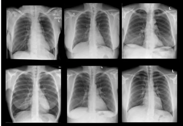
Radiography is the use of X-Rays beams to make visual of normally invisible parts of a patient. X-Rays are a narrow part of electromagnetic spectrum. X-ray produced in a vacuum environment, accelerating electrons from a hot wire called filament with high voltage electric field. Because of their energy and wavelength, X-Rays can pass through the body. During the travel they loose some of their energy with scattering and absorption. Lost energy depends of the length and the density of the tissue passed. Finally X-Rays are captured after left patient body with a media (usually a sensitive film) or a detector. As mentioned above, the energy of the X-Rays by varies by different tissues accordance with density and length that produces the image contours and contrasts which representations of all the organs, bones and other tissues in 2D projection (Suetens, 2009, Iniewsky, 2009, Berumen, 2011). Most used areas of conventional radiography are: Chest, Skeletal, Abdomen, Dental.
6
Figure 1.1: Radiographic Image Samples Of Chest 1.1.2 Fluoroscopy
This modality is an imaging type that uses also X-Rays to assure real-time representation of object. During the process, X-Ray production continues emitting. During beam-on time imaging system continuously acquire or screen show the projection so it is a type dynamic live imaging. This allows diagnosing with functioning organs. To make the images show better differentiation between organs and see circumvolution of the body, contrast materials may be injected into the patient. Barium is mostly used as a contrast agent, for example, barium swallow, for evaluation of the gastro-intestinal system. Hysterosalphingography is for evaluating the uterine cavity and the fallopian tubes. Retrograde urethrogram, micturating cysto-urethrogram for the evaluation of the abnormalities of the urinary system. Fistulography: for the evaluation of fistulae. Reduction of fractures under image guidance and so on (Berumen, 2011).
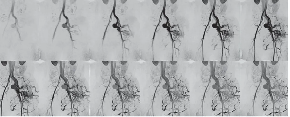
7 1.1.3 Angiography
Angiography in diagnostic imaging is used for the representation of the structures such as blood arteries, veins, heart, vessels other tissues. Intra venial contrast material is used in accordance with the use of X-Rays. There are two types of angiography machines. Today, conventional angiography is left its place to digital subtraction angiography. Because it needs operation involving wires and catheters driving in veins, procedures performed by angiography are replaced by non invasive methods such as CT or MRI angiography (Lanier, 2012).
8
Angiography is used mostly for diagnosis of obstructive vascular diseases, aneurisms and particularly intracranial aneurism, arterial-venous malformations, bleeding vessels, vascularity of malignant tumor assessments and used for image guided interventional procedures such as stent placements (Suetens, 2009, Iniewsky, 2009, Hendee, 2004, Lisle, 2001).
1.1.4 Mammography
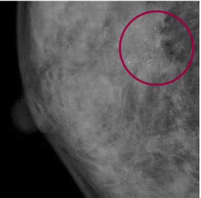
Mammography is an imaging modality that uses low energy x-rays specifically for imaging of breast tissue. Mammography practice utilizes standardized views of the breasts to for the assessment of breast lesions. It is also used as a screening tool for the detection of early breast cancer in asymptomatic women. Sample image is shown in Figure 1.3
Figure 1.3: Mammographic Image With Anomaly Marked Red Circle
Each breast is examined separately and compressed in between imaging equipment and X-Ray source to obtain maximum visualization of masses or calcifications. Early detection of breast cancer allows early treatment and increased
9
rates of survival. Image processing based on X-ray scattering kernels to produce scattering image and processing it with input image. Follow chart of this process is depicted on Figure 1.4.
Figure 1.4: Image proccesing in Mammography
Uses of mammography varies form screening for early diagnosis of cancer, diagnostic for the lesion inspection of already screened and identified breast, surveillance for reassurances of malignancy of treated patients.
1.1.5 Computed Tomography
Computed Tomography (CT) consists of an X-ray tube and detectors and involve with image reconstruction process. X-ray (photon) passes through patient and captured with linear array of sensors and the raw data recorded with the angle position of the tube and sensors. The raw data processed and reconstructed to create a two or three-dimensional and rendered images (see Figure 1.5, Figure 1.6).
Reconstructed data are form of cross-sectional slice through the patient in any angle or position of scanned area such as sagittal, axial and coronal. A decently calibrated CT unit can give density or attenuation of the inspected pixel in Hounsfield unit (HU) (Suetens, 2009, Lisle, 2001, Iniewsky, 2009, Hendee, 2004).
10
Figure 1.5: Reconstructed Image - Thorax Axial Slice Lungs and Heart
Intravenous and oral contrast material may be used during acquisition, which provides prominent structures of close or same density organs. It helps to determine abnormalities in organs such as bleeding, extravasation, etc.
CT has various range of uses such as: Brain, cranial, head and neck, pyelography, chest, mediastinum, abdominal, pelvic, urography, colonography, cardiac, angiography, Quantitative Computed Tomography (QCT), QCT Densitometry and simulations of radiotherapy patients and extremities.
11
Figure 1.6: Cinematic Rendering View of CT Images
1.1.6 Ultrasound and Doppler
Ultrasound is imaging provide images measuring the travel time of the sound waves. Cross sections are constructed with computers. Sound waves used are high frequency waves. Probe and transducers are the sensor of the machine which produces the sound wave at desired precise frequencies and captures the returning waves. Desired frequency determined by the tissue density. This modality is also real time acquisition and captured the movement of the organs (Iniewsky, 2009).
Doppler is a type of ultrasound uses Doppler shift effect and used for vascular area. Using sound waves is comparably cheaper than other imaging systems thus more available. It can be manufactured portable. It is also considerably safer since there is no ionizing radiation involved. One disadvantage is that it is more
12
operator dependent system than any other systems. Lack of knowledge and experience will cause inaccurate results.
Figure 1.7: Ultrasound Images (3) Showing Fetal Measurement
Common medical usage covers, abdominal area to inspection such as kidneys, liver, spleen, vascular structures, lymph nodes, pelvic area covers prostate, bladder, reproductive organs. Doppler is used for echocardiography. Obstetric usage is for assess the baby and its organs in pregnant women. Thyroid, breast, scrotum can be inspected with ultrasound also.
13 1.1.7 Magnetic Resonance Imaging
Magnetic Resonance Imaging (MRI) uses magnetic radiation to image structures of the body in high details. Although old types are not able to acquire and process images that fast, current MRI equipment are as fast as real time capture. The raw image data of the MRI is 3D and 2D slices in desired axis can be constructed from this raw data (see Figure 1.8, Figure 1.9, Figure 1.10). Most important advantage of MRI systems is the high contrast ratio of soft tissues such as brain, muscles, spine, joints, etc. MRI acquisition is based on tissue based predefined sequences (see Figure 1.11) of radio waves and gradient pulses captured by serious of sensors.
Figure 1.8: 3D Reconstruction Of Veins And Bones MRI
14
Figure 1.10: Sagittal Slices of Angiography MRI
15
Before MRI examination, the patient is to remove any metallic objects. All implants and other foreign bodies must be carefully evaluated for magnetic properties. Common clinical applications are same as CT but not limited (Iniewsky, 2009, Hendee, 2004, Berumen, 2011).
1.1.8 Nuclear Imaging
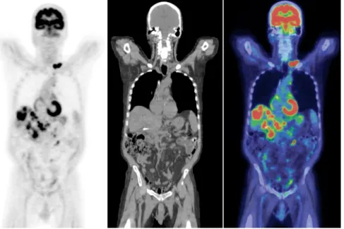
The most important difference between nuclear imaging and other imaging modalities is in nuclear imaging acquisition is done by capturing activity of the decay of radioisotopes that bound to molecules with known biological properties where other imaging modalities can only work with structures of the body.
Use of the radioisotopes that emits gamma rays and bounding this radioisotopes to a physiologically known chemical material, is the most common source of nuclear imaging. A gamma camera is used to detect the photons emitted by decay form isotopes. Gamma cameras have primary collimator made by lead used to block the rays that are not in the same axis with camera. When photons hit to the crystal scintillator, it emits visual light. Photo multiplier tubes used to amplify the light to create better images.
Two-dimensional captures, are called planar scintigrams. They are degraded by the superposition of non-target activity from the 3D body restricts the measurement of organ function and prohibits accurate quantification of that function. Single Photon Emission Computed Tomography (SPECT) is a technique whereby cross-sectional images of tissue function can be produced allowing the removal of the effect of overlying and underlying radioactivity (Larsson 1980, Williams 1985, Croft 1986, Ott 1986). Typical PET images can be seen in Figure 1.12
16
Figure 1.12: Pet Scan Sample
1.2 Digital Imaging Parameters and Quality Factors
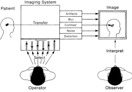
Medical imaging is a type of imaging that shows part of human body according to the type and its ability. Some type of imaging get good results for soft tissue the other for bones. Image quality and so the visibility of the organs varies with each method in accordance with the type of equipment, it’s operators skills. If it is related with an X-Ray the quality also depends on duration of exposure and amount of exposure itself. In Figure 1.13, general overview of the imaging process shown. An imaging system has a major unit of equipment, operator, result image and observer. The main purpose is to show the desired part of the body to an observer. There are many variables to be arranging by the operator in medical systems during acquisitions. These variables can be parts to be changed such as screens, type of transducers or coils for the different area of the body. (Hendee, 2004). Units or quantities such as gain, offset, echo time, voltage and current values are the adjustable variables of the imaging systems. These values will determine both the quality and visibility of the organ to be imaged. (Perry, 2016).
17
Figure 1.13: Components Associated With Medical Imaging Process Method chosen for imaging and the attributes of this system and the variables related with chosen method determines the quality of a medical image. Image quality is not just a constant or a single degree equation, the equation has five degree and they are shown in Figure 1.13: noise, blur, contrast, artifacts, and distortion. In a medical image there is not only one organ or structures to be acquired. It contains all the organs and structures in the region on the image. Even though we usually consider a single object in connection to close surrounding background. In reality, visibility of the structure is also determined by this relation instead of looking the general characteristic of total image in almost all acquisitions. Shown in Figure 1.14. Every acquisition system is to convert the tissue density to tone of gray or a specific color. If the contrast between tissues is adequate, organ or structure will be visible. Contrast varies with the structure to be acquired and the acquisition system itself.
18
Figure 1.14: Conversion of Tissue Characteristic To A Visual Image 1.2.1 Contrast
Difference is the word that most describe the contrast. For example different gray shades, different colors or even intensities of light are types of contrasts. In all characteristic of a medical image it is contrast that is the most important one. It is only possible to see the object or structure if the contrast is sufficient in relation to its border or surrounding organs. On the other hand, too much contrast is also not wanted.
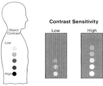
There should be physical contrast between at least on or more structures. In x-ray imaging, for example, density, thickness or atomic number of structures that make the contrast relation to neighbor structures. Since the contrast represents the differences there should be at least two points or area. These points usually are the organ and its surrounding background and the difference represents the contrast value. Also imaging systems requires a certain amount of physical structure contrast to be able to show the image. It is called contrast sensitivity of an imaging system the ratio between physical object contrast and the image contrast as shown in Figure 1.15. The size of the circular regions is the same but is made with different material with different density. So, each of them has different object contrast levels. If acquisition is done with low contrast sensitivity imaging device, only objects with high density also means high object contrast will be visible in the result. If it has high contrast sensitivity, the lower-contrast or density structures will also be visible in the image.
19
Figure 1.15: Relation Between Contrast Sensitivity And Visibility
As mentioned above the contrast sensitivity are not only the characteristic of the acquisition method but also the variables of the selected imaging system. To rephrase this: It is the ability of converting physical structural contrast to an image contrast.
This conversation or transfer of contrast can be seen in two ways. First, sufficient difference in contrast for visibility. Low-density objects will be visible by increasing the sensitivity level. Second, if the object has narrow bad of contrast variety, only contrast of the image will raise by increasing the sensitivity. Although some acquisition systems have higher contrast sensitivity compare to others, most of the imaging systems focused on different organs so it is hard to compare the contrast sensitivity of these systems. As an example soft tissue can be imaged with CT but cannot be imaged as good with conventional X-Ray system because CT systems has higher contrast sensitivity then conventional X-Ray systems. There is a matrix of objects with variety of physical contrasts shown in Figure 1.16. All members have different concentration of contrast material. Being the highest concentration at the bottom. Level of contrast sensitivity is such a level of blind moving down from the top and covering some of the objects so that they are no longer visible. Contrast sensitivity is the level of the blind. Increasing sensitivity makes the blind go up
20
letting you to see more. And low contrast sensitivity let you see only structures with high physical contrast.
Figure 1.16: Contrast Sensitivity vs. Visibility 1.2.2 Noise
Noise is another important variable of imaging. Grainy or textured appearance defined by image noise also called, mottle. In image quality image noise is only considered by its effect on the visibility. In Figure 1.17 same matrix of physical contrasts and sized used. Only third factor is added, noise. It acts as a boundary between visible and invisible areas.
The overall effect of raising image noise is to lower the curtain and decrease structure visibility. With very few exceptions for medical imaging noise effect is occur on the low-contrast organs that are already in or very threshold of visibility.
21
Figure 1.17: Noise Effect On Visibility 1.2.3 Distortion
Distortion is deviation of an image from the true contour or nature of an organ or tissue; it may be a change in size or shape, an elongation, a foreshortening, or a magnification. It is not desirable. A medical image should not only make internal body objects visible, but should give an accurate impression of their size, shape, and relative positions. Electric field, optical elements such as lenses and mirrors used in imaging can cause distortion of the image.
1.3 Scope Of The Thesis
In medicine diagnosis is a key to treatment decisions. Currently, in many cases, medical X-ray imaging devices are essential for rapid and reliable diagnosis that leads to accurate and fast treatment decisions. Unfortunately, in some developing countries, only %1 of the population can be diagnosed with such devices. Despite of other problems, lack of purchasing power is relates to the problem at the most. This thesis aimed to develop a reliable X-Ray imaging system which has accurate and acceptable results and at the same time comparably cheaper to the most affordable medical imaging system commercially available. In this thesis, computer based X-Ray image captured device has been developed using inexpensive consumer materials and results are compared with commercial products in accordance.
22 2 MATERIALS AND METHOD
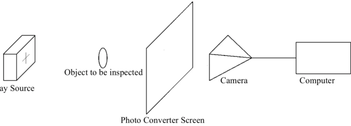
System consists of a scintillator sheet as a photo convertor screen and a camera that captures the light emitted by the scintillations. 2cm thick lead glass is used between camera and X-Ray to avoid noise produced by radioactivity hitting directly to charged coupled device (CCD). 2mm thick fiber plate used on top of convertor screen to protect the screen from external factors and act as a curtain to stop the visual light to enter the dark environment. Plywood box covered with black mate paper inside holds the system together providing non-reflective dark environment for the appropriate image capture. The native resolution of the camera is chosen to be at least equal to the resolution of the scintillator. Last component of the system is a computer to communicate with camera for image acquisition, holding and sending data to user.
2.1 Components Of The Designed System
Basic imaging needs three main components; X-Ray source, object to be imaged and capture media such as film, image intensifier, flat panel, etc. Block diagram of this system is shown in Figure 2.1
X-Ray source is not the focus of this thesis. Mecaserto Axim II Radiation Therapy Simulator is used as a general-purpose medical X-Ray source (Figure 2.13). X ray generator of this system is Magnum high frequency system with 40 – 150 kV, 10 – 800 mA radiography output capability. X-Ray tube has 0.3 x 0.8 mm focal spot size.
There are three critical pars of the imaging system designed: 2.1.1 Photo Converter Screen
Photo converter screen used is to convert X-Ray to visible light rays by emitting light due to the stimulation of radioactive rays. The type of the scintillator is used for this thesis is medical purpose Toshiba FU series scintillator sheet. This series uses poly crystal gadolinium material as a scintillator. Maximum emission wavelength is 512nm which is visible light and in capture range of the camera
23
system used. It has high sensitivity and hi sharpness ranges to be used in medical applications.
Figure 2.1: Block Diagram Of The Designed System
2.1.2 Single Board Computer
Computer has chosen for the system is Raspberry Pi. Raspberry Pi is a Single Board Computer (SBC) sized about a credit card. It has a 1.2 GHz 64bit ARM Cortex A53 Central Processor Unit (CPU). Commercial name for CPU is Broadcom BCM2837. 1Gb System memory consist of a mobile type double data rate synchronous DRAM (LPDDR) with 800MT/s data transfer rate. Video core is 400 MHz Broadcom Video Core IV. As storage High Capacity Secure Digital (SDHC) card is used. Power consumption of the bare system is only 800 mA (4 Watts). Along with General-Purpose Input Output (GPIO) ports, there is a camera serial interface (CSI) to connect the camera to CPU directly (Tivnan et al., 2015, Pereira et al., 2015, Paiva & Moreira Rde, 2014).
Xray Source
Object to be inspected
Photo Converter Screen
24
Figure 2.2: Photo of Raspberry Pi Single Board Computer 2.1.3 The Camera
System camera has 1/4" CMOS OmniVision OV5647 image sensor deliver 5 megapixel photographic images. Photo of the camera is in Figure 2.3. This camera provides full-frame 10-bit Raw RGB image, which is more capable than many image sensors used in medical imaging cameras. It also handles black level calibration automatically and connects to SBC with CSI. CSI has 10 Giga bits per second (Gbps) wide band transmission rate over for data lanes and 2-wire clock lane. S/N ration of this camera is 36dB, dynamic range is around 67dB at 8x gain, sensitivity is 680mV/lux.sec and dark current is 16mV/sec at 60 C. Dark current being as low as 16mV/sec is a key asset of dark imaging noises. Sensitivity is also good enough to handle contrast differences compare to commercial sensors (Tivnan et al., 2015, Pereira et al., 2015, Paiva & Moreira Rde, 2014). Camera and the computer combined shown in Figure 2.4.
25
Figure 2.3: Raspberry Pi Camera
Figure 2.4: Camera Connected to Raspberry Pi 2.1.4 Minor Components
The cross section of the design is shown in Figure 2.5. Other components of the system as follows:
Plywood Box and Black Mate Cover: 14mm tick plywood is used to construct a box to hold the system together and provide a dark environment for the image capture. Black mate paper used to eliminate the reflections.
Lead Glass: Lead glass is also called ‘X-Ray Glass’ or ‘Radiation Shielding Glass’. This glass provides, full radiation protection but is transparent and easy to see
26
through for observation purposes. It delivers good visual clarity and high light transmission with almost no distortion. For the energy level of 140kV 1,4 cm lead glass is used. Lead glass protects the camera and the computer from X-Rays which ensures to eliminate the radiation noise from X-Rays.
Fiber Plate: Opaque sheet needed to block the visual light to reach camera so 2mm tick fiber plate used. This plate also protects the converter screen.
USB Wifi Dongle: WIFI Dongle is connected to Raspberry Pi’s USB port to add WIFI capability to our system. To be able to use the system wirelessly without having a wireless access point, dongle is set up as a hot point.
27
Figure 2.6: Cross Section Of The Real Prototype
In Figure 2.6, Layer of the top of the built acquisition device can be seen. In Figure 2.7, there is a bottom view that shows the Raspberry Pi attached to the bottom of the system with WIFI dongle. Also there is a photo of the dark environment and camera device in Figure 2.8. Corner Holder Fiber Photo Converter Sheet Leaded Glass
28
Figure 2.7: Bottom View
29
2.2 Assembling And Setting Up The Image Capture System
After the procurement process of all the components, first step was setting up the Raspberry Pi hardware and operating system. The name of the operating system chosen for this thesis is Raspbian. Raspbian is a version of Debian Linux optimized for Raspberry Pi. It is official, open source and free stable and scalable operating system including programs and utilities. This operating system can use the ARM CPU of SCB for floating point intensive applications such as image capture and image process on hardware level. Thus it noticeably improves the performance of the SCB. Official Raspbian Jessie Lite OS Image downloaded from https://www.raspberrypi.org/downloads/raspbian/ and flashed to 4gb SD card. Pi camera connected to the camera port of the SBC with a flat cable. 5v power supply, keyboard, mouse and a monitor connected to the system. After booting the system, camera needed to be enabled from configuration menu. First visual captures were made in order to get the camera angle and focus ability. Camera was able to capture 23cm wide images from the distance of 22cm. With these measurements, box dimensions decided. 23cmx23cmx23cm cube made according to the cross section drawing. Matte black paper covered inside the box. SBC mounted under the box and camera mounted center of bottom of the box. SSH enabled in configuration menu. Also wireless USB dongle installed and setup as a hot point. This way remote computer connect to the SBC with WIFI and use SSH to give to control and file transfer. After this stage monitor, keyboard and mouse are not needed and unplugged. Lead glass placed on top of the box. 7x7 square pattern (Figure 2.9) printed and placed on top of the glass and captured. Captured imaged compared to the pattern to measure the lens and glass distortion. Fusion is made combining captured image and placing the center of the pattern. Images fused with inverse and difference procedures. Result image (Figure 2.10) shows the distortion from lens and lead glass are less then 0.4mm/23cm on the maximum distorted areas and decided to be ignored.
30
Figure 2.9: Lens Distortion Pattern 23cmx23cm
31
After distortion situation cleared, photo converter screen and fiber sheet cover placed on top of the lead glass and secured in place with aluminum corner profiles. Assembled system can be seen in Figure 2.11. Although it is not necessary to use it, power bank is used for mobility. Photo of the designed system during capture can be seen in Figure 2.12 (Carroll, 2011).
32
Figure 2.12: Another Photo of The System With X-Ray Device
33 2.3 Capture Software Alternatives
Three methods were considered to capture images with the designed system. First one is command line utility, which comes with Raspbian. It is called RASPISTILL. Raspistill command captures still photographs with the camera hardware installed as well as video. It works in Terminal Window. There are many features such as picture formats, effects, exposure modes, metering modes, automatic white balance modes can be choose with the Raspistill command right from command line.
Second method tried was using a python code to gain more control over camera. In this method long exposures times during image capture were possible to perform. With this ability, working with less radiation resulted low visual light on the intensifying screen were possible.
Third and last method tried was using Raspberry Pi and Matlab. There is support package on Matlab for Raspberry Pi (Figure 2.14). With this package, communicating with Raspberry Pi remotely via network and using its peripheral devices is possible with Matlab code. This allows us to be able to acquire from imaging devices and other connected sensors at the same time. With this method, images captured are in a matrix form data directly used by Matlab code for image processing.
34
35 3 RESULTS
First raw images captured with the designed systems are seen in Figure 3.1, Figure 3.2, Figure 3.3 and Figure 3.4
36
37
38
Figure 3.4: Captured Image 4 (Allen Keys and Screw Driver) @ 90kV, 1sec Calibration phantom is used to measure the success of the capture. Calibration phantom is 12mm thick aluminum block, which has holes with 10 different diameters in rows and 10 different levels of depths in columns. Photograph of the phantom is presented in Figure 3.5.
39
Figure 3.5: Calibration Phantom
The raw image of the Calibration phantom acquired with the designed system is shown in Figure 3.6. In this image holes on the phantom can be seen.
Figure 3.6: Raw Image of Calibration Phantom Captured
3.1 Image Process
Image process is made on Matlab. Contrast Limited Adaptive Histogram Equalization (CLAHE) and histogram equalization algorithms are used on the
40
captured raw image (Figure 3.6) and the result of the process is show in Figure 3.7.(Pisano et al., 1998, Jin et al., 2001)
Processed image has significantly improved edges and contrasts thus, has more holes appeared. Comparison table between raw and processed image is on Table 3.1. (Suetens, 2009, Lisle, 2001, Hendee, 2004, Feeman, 2010)
Figure 3.7: Processed Image
Raw Image Processed Image
C/R 1 2 3 4 5 6 7 8 9 10 1 2 3 4 5 6 7 8 9 10 1 ✖ ✖ ✖ ✔ ✔ ✔ ✔ ✔ ✔ ✔ ✔ ✔ ✔ ✔ ✔ ✔ ✔ ✔ ✔ ✔ 2 ✖ ✖ ✖ ✔ ✔ ✔ ✔ ✔ ✔ ✔ ✔ ✔ ✔ ✔ ✔ ✔ ✔ ✔ ✔ ✔ 3 ✖ ✖ ✖ ✖ ✔ ✔ ✔ ✔ ✔ ✔ ✖ ✔ ✔ ✔ ✔ ✔ ✔ ✔ ✔ ✔ 4 ✖ ✖ ✖ ✖ ✖ ✔ ✔ ✔ ✔ ✔ ✖ ✖ ✖ ✔ ✔ ✔ ✔ ✔ ✔ ✔ 5 ✖ ✖ ✖ ✖ ✖ ✖ ✔ ✔ ✔ ✔ ✖ ✖ ✖ ✖ ✖ ✔ ✔ ✔ ✔ ✔ 6 ✖ ✖ ✖ ✖ ✖ ✖ ✖ ✖ ✔ ✔ ✖ ✖ ✖ ✖ ✖ ✖ ✔ ✔ ✔ ✔ 7 ✖ ✖ ✖ ✖ ✖ ✖ ✖ ✖ ✖ ✔ ✖ ✖ ✖ ✖ ✖ ✖ ✖ ✔ ✔ ✔ 8 ✖ ✖ ✖ ✖ ✖ ✖ ✖ ✖ ✖ ✔ ✖ ✖ ✖ ✖ ✖ ✖ ✖ ✔ ✔ ✔ 9 ✖ ✖ ✖ ✖ ✖ ✖ ✖ ✖ ✖ ✖ ✖ ✖ ✖ ✖ ✖ ✖ ✖ ✖ ✖ ✔ 10 ✖ ✖ ✖ ✖ ✖ ✖ ✖ ✖ ✖ ✖ ✖ ✖ ✖ ✖ ✖ ✖ ✖ ✖ ✖ ✔ T 0 0 0 2 3 4 5 5 6 8 2 3 3 4 4 5 6 8 8 10
41 3.2 Bill Of Materials
Items Cost
Raspberry Pi Model B+ 50TL
Raspberry Pi Camera V1.3 (comes with cable) 45TL
Sd Card 8gb 25TL
Power Supply 5V, 2A 15TL
Wifi USB Stick (Optional) 15TL
Plywood 1m x 1m 20TL
Lead Glass 10TL
Intensifying Screen 10TL
Black Card Board 1m x 1m 4TL
Fiber Plate and Corner Profile 10TL
Total Cost Of The Prototype 199TL
Table 3.2: Bill Of Materials / Approximate. Cost of the Prototype 3.3 Comparison Of The Aquired Images With The Developed System And
Two Commercial Systems Available
There are two systems available to compare with the system designed: Digital X-Ray detector array and a image intensifier system.
First system is Perkin Elmer XRD 1640 digital x-ray detector based on amorphous silicon sensors in form of a two dimensional array. The panel can achieve 16bit digitization with 1024x1024 pixels resolution. This panel is designed for medical applications and has a special PCI card and a program to capture the images (Perkinelmer, 2013).
Photo of the panel is in Figure 3.8. The acquired image with this panel is shown in Figure 3.9.
42
Figure 3.8: XRD 1640 Perkin Elmer Digital X-Ray Detector
43
Image intensifier system consists of image intensifier vacuum tube and a camera shown in Figure 2.13. Diameter of the area can be inspected is 22cm. There is no digital image output so the result image is captured from the screen. But results compared according to view on site. Captured image is shown in Figure 3.10. Image distortions caused by image intensifier tube can be seen on the photo (Dougherty, 2009).
Figure 3.10: Image Captured By Classic Image Intensifier Tube and Cooled CCD camera @80kV, 1sec
Comparison of the three systems is on Table 3.3. Soft tissue equivalence of the first column row 10 and row 9 is about one tenth of a millimeter. With this scale the system developed is able to detect 0.5mm soft tissue thickness changes or equivalent density changes where image intensifier system has 0.4mm and Flat Panel
44
System has 0.3mm ability. All there system is able to detect any irregularities up to 0.1mm in hard tissues such as bones. Therefore, the system designed has not big difference with the commercial systems and proved be used in most medical cases.
Number of Column:
Compared System 1 2 3 4 5 6 7 8 9 10
Designed System 2 3 3 4 4 5 6 8 8 10
Image Intesifier + CCD Camera 4 5 7 7 7 9 9 9 10 10 A-Si Flat Panel 4 4 8 9 9 9 10 10 10 10
45 4 DISCUSSION
To sum up the work completed; Digital X-Ray image acquisition system has been designed and a working prototype is built with using mostly consumer parts at the cost of 200TL. Acquired images with this system are proved to be able to used for diagnoses and pre diagnoses purposes. It has an advantage of real time imaging like two compared commercial systems.
X-ray from medical devices is in form of pulsed signals, not continuous. Catching the peak signal is essential to imaging. It reduces the acquisition time and so improves the quality of the images. Both Flat panel and image intensifier systems using external trigger signal from the machine for correct timing of imaging. Even though it is possible to get trigger signal with one of the Raspberry Pi’s IO ports. We were not able to get permission from authorities to interface with medical device. Optically isolated trigger input and synchronizing image capture timing with the medical device should be one of the design considerations for future systems.
Resolution of the phosphor screen used and diffusion of the image on the panel is the main restriction couldn’t have been eliminated. There is no phosphorus screen available with better resolution. In the future researchers from other disciplines may be joined to the team and develop screen with better response and resolution.
The system designed is completely mobile, and works wireless. It can run a week with 10000mAh battery pack. There are no consumables needed. It can store more than 1000 patients data internally. With its compact light and close design it is durable to all conditions including dust, extensive heat and humidity.
Developing user-friendly software for clinical use will complete the system. DICOM compatibility and a PACS server also can be added easily.
Another future work would be building a cone beam Computerized Tomography (CT) system using the developed acquisition device.
Developed system can also be used in other fields such as Non-Destructive Testing (NDT) of materials.
46
As we seen on results, developed imaging system is capable and alternative to commercially available systems in most cases.
47 5 BIBLIOGRAPHY
Berumen, A. V., 2011, WHO Perspective on Health Technologies: Medical Imaging, Carroll, Q. B., 2011, Radiography in the Digital Age,
Dougherty, G., 2009, Digital Image Proccessing fot Medical Applications. Feeman, T. G., 2010, The Mathematics of Medical Imaging,
Hendee, W. R., 2004, Medical Imaging Physics,
Iniewsky, K., 2009, Medical Imaging Principles, Detectors and Electronics.
Jin, Y., Fayad, L. M. and Laine, A. F., Contrast enhancement by multiscale adaptive histogram equalization. in Proceedings of the International Symposium on Optical Science and Technology, 2001, p. 206-213.
Lanier, R. G., 2012, Recent Developments in X-ray Imaging Techonology. Lisle, D. A., 2001, Imaging for Sutudents.
Paiva, O. A. and Moreira Rde, O., 2014, Raspberry Pi: a 35-dollar device for viewing DICOM images, Radiol Bras, 47, 99-100p.
Pereira, A., Atri, M., Rogalla, P., Huynh, T. and O'Malley, M. E., 2015, Assessment of feasibility of running RSNA's MIRC on a Raspberry Pi: a cost-effective solution for teaching files in radiology, Int J Comput Assist
Radiol Surg, 10, 1793-1801p.
Perkinelmer, 2013, Product Note, XRD 1642 AP Flat Panel X-ray Detector. Perry, S., 2016, Image Characteristics and Quality.
Pisano, E. D., Zong, S., Hemminger, B. M., DeLuca, M., Johnston, R. E., Muller, K., Braeuning, M. P. and Pizer, S. M., 1998, Contrast limited adaptive histogram equalization image processing to improve the detection of simulated spiculations in dense mammograms, J Digit Imaging, 11, 193-200p. Suetens, P., 2009, Fundamentals of Medical Imaging,
Tivnan, M., Gurjar, R., Wolf, D. E. and Vishwanath, K., 2015, High Frequency Sampling of TTL Pulses on a Raspberry Pi for Diffuse Correlation Spectroscopy Applications, Sensors (Basel), 15, 19709-19722p.
48 6 APPENDICES
6.1 Setting Up The Wireless Access
sudo apt-get install dnsmasq hostapd sudo systemctl stop dnsmasq
sudo systemctl stop hostapd sudo nano /etc/dhcpcd.conf
Add denyinterfaces wlan0 to the end of the file
sudo nano /etc/network/interfaces Add allow-hotplug wlan0
iface wlan0 inet static address 192.168.0.1 netmask 255.255.255.0 network 192.168.0.0 sudo service dhcpcd restart sudo ifdown wlan0
sudo ifup wlan0
sudo mv /etc/dnsmasq.conf /etc/dnsmasq.conf.orig sudo nano /etc/dnsmasq.conf
Add interface=wlan0
Dhcp range=
192.168.0.2,192.168.0.20,255.255.255.0,24h sudo nano /etc/hostapd/hostapd.conf
Add interface=wlan0 driver=nl80211 ssid=RPIPORTALVISION hw_mode=g channel=7 wmm_enabled=0 macaddr_acl=0 auth_algs=1 ignore_broadcast_ssid=0 wpa=2
49
wpa_passphrase=IKCBIOMED wpa_key_mgmt=WPA-PSK wpa_pairwise=TKIP rsn_pairwise=CCMP
sudo nano /etc/default/hostapd
Add DAEMON_CONF="/etc/hostapd/hostapd.conf" sudo service hostapd start
sudo service dnsmasq start
6.2 Raspistill Command
raspistill -f -sh 100 -co 100 -br 60 -awb fluorescent -bm -mm matrix -ss 20000 -drc high -o phantom60kv3ma03042017_09.tif
6.3 Installation Of The Pi Camera Module For Python
python -c "import picamera" python3 -c "import picamera" or
sudo apt-get update
sudo apt-get install python-picamera python3-picamera sudo apt-get update $ sudo apt-get upgrade
6.4 Python Program Using Pi Camera Module To Capture X-Ray Images
from picamera import PiCamera from time import sleep
from fractions import Fraction
camera = PiCamera(resolution=(2592,1944),framerate=Fraction(1,6),
sensor_mode=3)camera.shutter_speed = 6000000 camera.iso = 800
50
sleep(30)
camera.exposure_mode = 'off'
camera.capture('x.data',’yuv’)
6.5 Matlab Code For Image Capture
clear rpi clear cam rpi = raspi();
cam = cameraboard(rpi,'Resolution','2592×1944'); for a = 1:5
I = snapshot(cam); end
imwrite(I,'c:\phantom70kv6ma0404217_23.tif')
6.6 Matlab Code For Image Processing
I = imread ('c:\phantom70kv6ma04042017_11.tif'); # I = snapshot (cam);
J = adapthisteq (I,'cliplimit',0.04,'Distribution','Exponential'); K= histeq (J);
51 7 CURRICULUM VITAE
Alpman Manalp
+90 (533) 332 30 82 - [email protected]
915/1 Sok. No:28 Ataturk Mah. Bornova Izmir 35030 Turkey
Proven performer and results oriented professional who has seventeen year of experience in Engineering Design, Management, Installation, Commissioning, Preventive Maintenance, Service, Contract Administration and Procurement with expertise in Radiation oncology and medical imaging facility construction and Medical Linear Accelerators, CT and MRI systems. Strong analytical and quantitative skills implemented in design, problem solving and development activities, harmonized with multi-cultural working environment and diversified team management abilities.
Professional Experience
Technical and Biomedical Manager 06.2005 - Current
Ege Onkoloji Merkezi Ltd. Sti.
- In charge of technical and IT department,
- Planning, designing, budgeting and managing the development projects, technical, manufactural and constructional operations.
- Dealing with local authorities from the beginning to the completion of the project in terms of project requirements, budget and time.
- Leads development projects
- Generates operation procedures, develop technical and operational strategies, - Contract Administration such as maintenance service agreements, procurement agreements for technical consumables, spare parts and accessories.
- Preventive maintenance and repair of medical devices and their auxiliary equipments.
- Offers training and medical physics department support. - Supports job safety and health activities.
- Generates marketing materials as technical papers.
Project and System Development Engineer 01.1998 - 05.2005 ESBAS Aegean Free Zone Dev. and Opr. Co.
- Member of the management team for turn key industrial plant construction projects for tenants.
52
- Project Based Planning, Budgeting, Cost Control and Management. - Procurement planning
- Infrastructural and Structural Design and Calculations, Land development - Other municipal and custom services, construction supervising.
Education
Ege University Nuclear Science Institute
Phd. in Nuclear Applications 2011 - Current Katip Celebi University 2014 - Current
M.Sc. in Biomedical/Electronic Engineering
University of Washington,Civil and Environmental Engineering Faculty
M.Sc. in Structural Engineering 1996-1997
Karadeniz Technical University 1991-1995
B.Sc. in Civil Engineering
Skills
Technical Knowledge:
Troubleshooting and maintenance of Medical Accelerators; High and Low Voltage A/D Electronics, Computers, RF, Gas, Pneumatic and Mechanical systems.
Computer Proficiency:
CAD/CAM: Microstation, AutoCad, NAMD,VMD STRUCTURAL ANALISYS: SAP2000, Ansys
SIMULATION: GEANT 4/GAMOS, MNCP, EGSNRC PM: MS Project, Primavera, Basecamp, JIRA
Programming: Matlab, C++, C#, Phyton, LaTeX, Simulink, CUDA, MASM, Delphi, Pascal, Basic, Fortran, MS Visual Studio, X code, Bash, G-Code