GRADUATE SCHOOL OF NATURAL AND APPLIED SCIENCES
THESIS
REPUBLIC OF TURKEY
YILDIZ TECHNICAL UNIVERSITY
GRADUATE SCHOOL OF NATURAL AND APPLIED SCIENCES
ANALYSIS AND SYNTHESIS OF REFLECTARRAY ANTENNA
SELAHATTİN NESİL
PhD. THESIS
DEPARTMENT OF ELECTRONICS & COMMUNICATION
ENGINEERING
PROGRAM IN TELECOMMUNICATIONS
ADVISER
REPUBLIC OF TURKEY
YILDIZ TECHNICAL UNIVERSITY
GRADUATE SCHOOL OF NATURAL AND APPLIED SCIENCES
ANALYSIS AND SYNTHESIS OF REFLECTARRAY ANTENNA
A thesis submitted by Selahattin NESİL in partial fulfillment of the requirements for thedegree of PhD (DOCTOR OF PHILOSOPHY) is approved by the committee on 21.07.2014 in Department of Electronics and Communication Engineering
Communication Engineering Program.
Thesis Adviser
Prof. Dr. Filiz GÜNEŞ Yıldız Technical University Co-Adviser
Prof. Dr. Bahattin TÜRETKEN Karabük University
Approved By the Examining Committee
Prof. Dr. Filiz GÜNEŞ
Yıldız Technical University _____________________ Prof. Dr. Bahattin TÜRETKEN, Member
Karabük University _____________________ Prof. Dr. Ahmet Serdar TÜRK, Member
Yıldız Technical University _____________________ Prof. Dr. Hasan DİNÇER, Member
Istanbul Kültür University _____________________ Assoc. Prof. Dr. Erdal KORKMAZ, Member
Fatih University _____________________ Assist. Prof. Dr. Ş. Taha İMECİ, Member
Istanbul Commerce University _____________________ Assist. Prof. Dr. Salih DEMİREL, Member
ACKNOWLEDGEMENTS
I wish to express my sincere appreciation to my advisor, Prof. Dr. Filiz GÜNEŞ, for constant support, precious scientific discussions, providing me an excellent working environment and helping me to have better perspective in my scientific thinking throughout my doctorate. She will always be in my memories as a very kind and splendid personality.
I also wish to express my sincere thanks to Prof. Dr. A. Serdar TÜRK and Prof. Dr. Sedef KENT for serving on my thesis committee. I highly appreciate their interest in my study as well as their precious comments and questions.
I would like to offer my special thanks to my co-advisor, Prof. Dr. Bahattin TÜRETKEN for his valuable and constructive suggestions during the planning and development at the outset of this thesis.
I would like to express my deep gratitude to Assist. Prof. Dr. Salih DEMİREL for his guidance, encouragement during my thesis. I deeply thank him for helping me in understanding the theoretical concepts of optimization techniques as well as the computer applications. And also he always helped me whenever I was in need. I am very grateful to him.
I am equally indebted to Assoc. Prof. Dr. Erdal KORKMAZ for providing all needed equipment, material and software and for ensuring the harmony within his group. I offer my special thanks to him for his all support and help.
I am very grateful to my wife, Atike NESİL for her endless emotional support and understanding during my doctoral dissertation.
None of this would have been possible without the prayers, support and encouragement of my parents. I owe them everything. Their continuous prayers had always given me a hidden support and confidence.
July, 2014
TABLE OF CONTENTS
PageLIST OF SYMBOLS ... vii
LIST OF ABBREVIATIONS ... viii
LIST OF FIGURES ... ix
LIST OF TABLES ... xii
ABSTRACT ... xiii
ÖZET ... xv
CHAPTER 1 INTRODUCTION ... 1
1.1 Literature Review ... 1
1.2 Objective the Thesis ... 4
1.3 Hypothesis ... 5
CHAPTER 2 FUNDAMENTALS OF REFLECTARRAY ANTENNAS ... 6
2.1 Reflectarray Antenna Concept ... 6
2.2 Microstrip Reflectarray Antennas (MRA) ... 7
2.2.1 Advantages of MRA ... 9
2.2.2 Disadvantages of MRA ... 10
2.3 MRA Design and Analysis Techniques ... 10
2.3.1 H-wall waveguide simulator technique ... 11
2.3.2 Infinite Array Approach ... 12
2.3.3 Path Length and Phase Shift ... 13
2.4 Radiation Pattern Analysis of Reflectarray Antennas ... 15
CHAPTER 3 DESIGN AND ANALYSIS OF MINKOWSKI RA USING PARTICLE SWARM OPTIMIZATION BASED ON MLP NN ... 17
3.1 Introduction ... 17
3.2 Reflectarray Element Design Analysis ... 18
3.2.1 Generation of the Training and Validation Data ... 18
3.2.2 Black-Box Model ... 21
3.2.3 Performance of the MLP Black Box Model ... 24
3.3 The Optimization of the Minkowski Element with Particle Swarm Algorithm ... 32
3.4 Design of Minkowski RA with Substantially-Optimized Parameters ... 35
3.5 Results and Discussion for the Optimum Minkowski Reflectarray Antenna 37 CHAPTER 4 A NOVEL DESIGN APPROACH USING HYBRID GA-NM OPTIMIZATION BASED ON COMPLETE MLP ANN MODEL ... 43
4.1 Introduction ... 43
4.2 Reflection Phase Characterization of Minkowski Unit Element ... 44
4.3 MLPNN Black-box modeling in the analysis ... 45
4.4 The Optimization of Minkowski Element using the Memetic Algorithm .... 49
4.4.1 Objective Function ... 49
4.4.2 The Memetic Algorithm ... 50
4.4.3 Tolerance analysis of the optimization ... 54
4.5 Design and Analysis of Minkowski RA with Fully-Optimized Parameters . 56 4.6 Circular Polarization Characteristics of Fully-Optimized Minkowski RA ... 62
CHAPTER 5 CONCLUSION ... 65
REFERENCES ... 67
LIST OF SYMBOLS
c Speed of light in free space e Electron charge
f Frequency
D Vertical edge size of array surface F Focal distance of feed antenna
r
f Resonance frequency h Substrate thickness
k Propagation constant in the medium m Length of the patch
M Number of divisions in x-direction N Number of division in y-direction n Cavity ratio of minkowski patch
Dielectric permittivity
e
Effective dielectric permittivity
r
Relative dielectric constant of the substrate
s
Spillover efficiency
t
Taper efficiency
g
Propagation constant in waveguide
0
Free space wavelength
r
Wavelength in the substrate Dielectric permeability Loss angle
LIST OF ABBREVIATIONS
ANN Artificial Neural Networks
CST Computer Simulation Technology GA Genetic Algorithm
MLP Multi Layered Perceptron MRA Microstrip Reflectarray Antenna MWS Microwave Studio
NASA National Oceanic and Atmospheric Administration NM Nelder-Mead
NN Neural Networks
PBC Periodic Boundary Condition PSO Particle Swarm Optimization RA Reflectarray Antenna
SLL Side Lobe Level
LIST OF FIGURES
PageFigure 1.1 Waveguide reflectarray antenna with staggered rows [5] ... 2
Figure 1.2 Reflectarray using a 4-arm spiral as element with switching diodes at center to achieve a 2-bit phase-shift system for circular polarization [4] ... 3
Figure 2.1 Reflectarray radiating elements [4] ... 7
Figure 2.2 Basic geometry of a MRA ... 8
Figure 2.3 Differential spatial phase delay of reflectarray [4] ... 13
Figure 2.4 Coordinate system for pattern analysis of RAs ... 15
Figure 3.1 Waveguide one-port with the TEM mode propagation boundary conditions to determine the amplitude and phase of the reflected wave from a minkowski unit cell ... 19
Figure 3.2 Geometry of minkowski shape ... 20
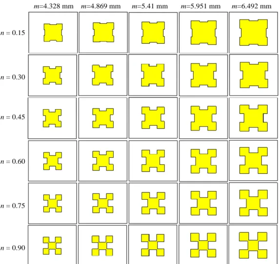
Figure 3.3 6 x 5= 30 minkowski configuration set for each substrate and frequency (f) sampling couple ... 21
Figure 3.4 Black-box analysis model of a minkowski radiator A: M
4 1 ... 22Figure 3.5 The Structure of MLP NN model for minkowski patch including 4 input and 1 output neurons with 2 hidden layers both of 10 neurons. ... 23
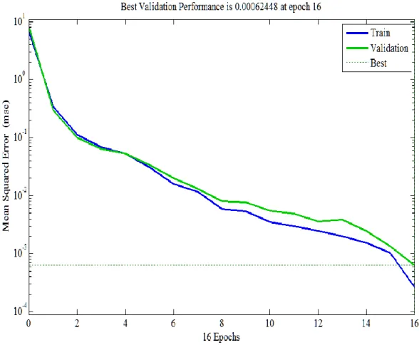
Figure 3.6 Mean squared error variation of the MLPNN model of the minkowski RA ... 24
Figure 3.7 Linear regression scattering plot for minkowski ANN model (a)training and (b) testing, (training MSE error =3.5992x10⁻⁴, testing MSE error =4.0192x10⁻⁴) ... 25
Figure 3.8 Reflection phase characteristics of the minkowski patch radiator against the patch length due to the f = 11 GHz, εr =3.54 (Taconic RF-35) and, h=1.25mm, taking different the iteration factor n values. ... 26
Figure 3.9 Reflection phase characteristics of the minkowski patch radiator against the patch length at the f =11 GHz, r=3.54(Taconic RF-35), taking parameters; iteration factor n for the substrate thicknessh1.5 mm; .... 26
Figure 3.10 Reflection phase characteristics of the minkowski patch against the patch length due to the f = 11 GHz, εr =3.54 (Taconic RF-35) and, h=1.75 mm, taking different the iteration factor n values. ... 27
Figure 3.11 Reflection phase characteristics of the minkowski patch against the patch length due to the f = 11 GHz, εr =3.54 (Taconic RF-35) and, n = 0.45, taking different the substrate thickness h values. ... 27 Figure 3.12 Reflection phase characteristics of the minkowski patch radiator against
the patch length at the f =11(GHz), r=3.54(Taconic RF-35), taking
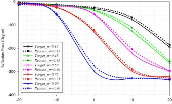
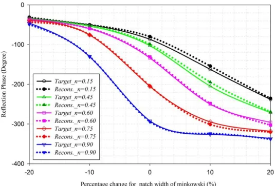
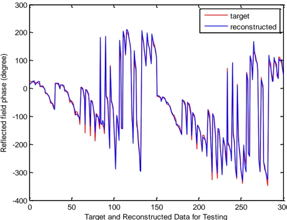
Figure 3.13 Testing performance of MLP NN in comparison between target and reconstructed data ... 29 Figure 3.14 Comparison of reflection phase values w.r.t m (patch variation) and ɳ
(iteration factor) for h = 1.52 (mm), f = 10.5 GHz with (a) the target data; (b) the reconstructed data ... 30 Figure 3.15 Comparison of reflection phase values w.r.t m (patch variation) and ɳ
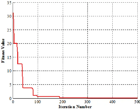
(iteration factor) for h = 1.524 mm, f = 11.5 GHz with (a) the target data; (b) the reconstructed data ... 31 Figure 3.16 Flow chart of the PSO Algorithm [51] ... 33 Figure 3.17 Convergence curve for the PSO of the minkowski element (nopt 0.7891,
1.4516 mm) opt
h with the resulted value of the objective 4.2x10⁸ ... 34 Figure 3.18 According to optimum parameters f 10.875 GHz n0.7891
1.4516 mm
h reflection characteristics of the minkowski Reflectarray element by comparison with square patch on the Taconic RF-35 (εr =3.54)
substrate ... 34 Figure 3.19 A General design procedure for a minkowski reflectarray antenna ... 35 Figure 3.20 2-D view of the center feed reflectarray antenna geometry [53] ... 36 Figure 3.21 Phase compensation variation with respect to the radial distance for
/ 0.8
F D at various operation frequencies ... 37 Figure 3.22 The 15x15 microstrip reflectarray antenna (a) minkowski (b) square with
the optimum parameters 0.789, 1.4516mm, on 20 X 20 cm, 3.54 (Taconic RF-35) ... 38 Figure 3.23 Effect of the feed movement on the max. gain variations of the 15 x 15
minkowski RA with the optimum parameters
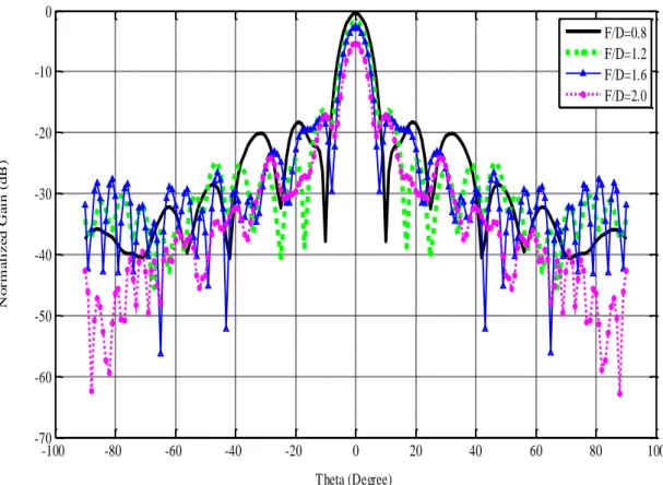
on 3.54 (Taconic RF-35) for different F/D ratios within the X-band frequency range ... 38 Figure 3.24 Effect of the feed movement on radiation pattern of the 15x15 minkowski
RA at 11 GHz with the optimum parameters
on 3.54 (Taconic RF-35) ... 39 Figure 3.25 Comparative radiation patterns of the optimized and non-optimized 15x15
minkowski RAs for the various values of (h, n) sets for F/D= 0.8 at 11 GHz ... 40 Figure 3.26 Comparison of radiation patterns for the 15x15 minkowski, square
reflectarray and the parabolic reflector antennas for parameters; 1.4516 mm, 0.7891 mm, ε 3.54 Taconic RF-35 ... 41 Figure 4.1 Black-box model II ... 45 Figure 4.2 The MLP NN structure ... 46 Figure 4.3 Linear regression scattering plots for the complete minkowski MLP model
(a) Training (MSE= 9.9564x10⁻⁵) and (b) Validation (MSE= 1.7264x10⁻⁴). ... 46 Figure 4.4 Reflection phase characteristics taking dielectric property as parameter for
(a)h 1 mm,n0.60,f 11 GHz;(b) n0.90, r 3, f 11 GHz;
c r 3, h1.5 mm, f 11 GHz. ... 48 Figure 4.5 3-D reflection phase variations versus the patch width m and the relativepermittivity of substrates, rfor the fixed conditions of 1.5 mm, 0.6, 11 GHz
h n f for (a) target and (b) reconstructed data . 49 Figure 4.6 Convergence performances of the genetic and memetic optimization ... 52
Figure 4.7 Reflection characteristics of the optimum minkowski reflectarray element with the parameters of r 3.1694, hopt 1.7916 mm, nopt 0.8438at f=11GHz as compared with the square patch’s values having the same resonance frequency. ... 53 Figure 4.8 Sensitivity analysis results for the optimum dielectric constant for the
standard deviation sigma values: a σ 0.01, b σ 0.05 c σ 0.1 at f=11 GHz. ... 55 Figure 4.9 Comparison of the reflection phase responses for unit cell element
designed with optimized parameters and two equivalent commercially available substrates ... 56 Figure 4.10 Required compensation phases for 15x15 minkowski RA with F/D= 0.8 at
11 GHz ... 57 Figure 4.11 A general design procedure for a minkowski reflectarray antenna ... 58 Figure 4.12 (a) Fully-optimized RA with ropt=3.1694, hopt =1.7916mm, nopt=0.8438;
(b) Non-optimized RA with r=2.2, h=1.5mm, n=0.90. ... 59 Figure 4.13 Realized gain versus frequency graphs for the fully optimized RA and the
other RAs on the different substrates with the optimized parameters
nopt,hopt
... 61 Figure 4.14 Realized gain versus frequency variations for the comparison of fullyoptimized RA with only patch geometry nopt optimized RAs on the given
dielectric permittivity rand substrate thickness h ... 61 Figure 4.15 Vector illustration of circular slant polarization ... 62 Figure 4.16 Circular polarization characteristics of optimized minkowski RA at 11
GHz for slant angle 15° ... 63 Figure 4.17 Circular polarization characteristics of fully-optimized minkowski RA at
11 GHz for slant angle 30° ... 63 Figure 4.18 Circular polarization characteristics of fully-optimized minkowski RA at
LIST OF TABLES
Page Table 3.1 Typical results for comparison of target and reconstructed data ... 28
Table 3.2 Reflection phase with optimum parameters; f 10.875 GHz,
3.5 Taconic RF 35 ,
r
nopt 0.7891, hopt 1.4516 mm, ... 35
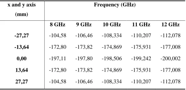
Table 3.3 Typical phase compensation values at various operation frequencies ... 37 Table 3.4 Radiation pattern characteristics of the 15x15 minkowski reflectarray
antenna with the optimum parameters: .. 39 Table 3.5 Comparison of the radiation pattern characteristics of the 15x15
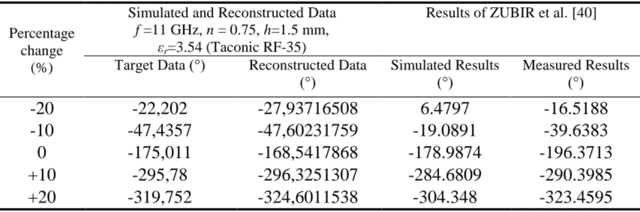
minkowski, square reflectarray and the parabolic reflector antennas ... 41 Table 4.1 Comparison for reconstructed data by ANN with the simulated data for
conditions f =11 GHz, n = 0.75, h=1.524 mm, εr=3.54 (Taconic RF-35) and
the measured results in [41]. ... 47 Table 4.2 3-D EM simulated reflection phases of the optimum MRA and constructed
phases by the complete ANN response at f=11GHz ... 53 Table 4.3 Performance comparison of the fully optimized reflectarray with a non-optimized reflectarray ... 60 Table 4.4 Comparison of the fully optimized RA and the other RAs designed on the
different substrates with same optimized parameters (nopt, hopt) ... 60
Table 4.5 Comparison of the Fully Optimized RA and RAs with the optimized minkowski shapes on the traditional substrates. ... 62 Table 4.6 Circular polarization characteristics of fully-optimized minkowski RA... 64
ABSTRACT
ANALYSIS AND SYNTHESIS OF REFLECTARRAY ANTENNA
Selahattin NESİL
Department of Electronics and Communication Engineering PhD. Thesis
Adviser: Prof. Dr. Filiz GÜNEŞ
Co-adviser: Prof. Dr. Bahattin TÜRETKEN
In this thesis, a design, optimization and analysis methodology, which is a novel, robust and systematic, is presented for an X-band microstrip reflectarray antenna (MRA). In this work, the two microstrip reflectarray designs have been carried out. The purpose of this thesis is to design a microstrip reflectarray, which has better radiation performance by determining the optimal geometry for the reflective patch element and dielectric substrate properties. In the designing of MRA, the most important and critical stage is the selection of patch element and its design optimization. In this work, the minkowski shape, which is from the first iteration of fractals, has been utilized as the radiating element, because of it has wider phase range in the linear region. In the first design, the reflection phase characterization of the minkowski unit element, which is placed at the end of the H-wall waveguide simulator on the substrate Taconic RF-35 ε 3.54, 0.018 , has been generated as a nonlinear variation function. This function was generated by 3-D EM simulations based on Computer Simulation Technology Microwave Studio (CST MWS) for the continuous domain of the patch geometry and substrate sizes within X-band region centered at resonant frequency. Thereafter, the Multi-Layer Perceptron Neural Network (MLP NN) model have been created to characterize the minkowski RA unit element. Following that, the Particle Swarm Optimization (PSO) has been utilized to optimize the minkowski reflectarray with simplified multi-objective functions to determine the phase calibration characteristic having the maximum phase range and the slower gradient. In the design stage, the MLP NN model has been used as reverse model to determine the variable-size of each reflectarray element by providing the necessary phase delay with the adaptive iterative step. Thus, the minkowski reflectarray antenna, which is designed with optimum parameters, has been analysed using the 3-D CST simulations and has been compared with the counterpart square and parabolic reflector antennas. In the second
minkowski reflectarray using a complete 3-D CST MWS- based MLP NN model including the dielectric constant of substrate, via hybrid combination of Genetic (GA) and Nelder-Mead (NM) algorithms. Herein, the performed MLP NN model has been an accurate and fast model to get the reflection phase of minkowski RA element as a continuous function with the input domain including the substrate characteristics 1 0.5 mm 3 mm , within the X-band frequency region. Finally, a design of a fully optimized X-band × minkowski RA is performed and so compared with the both optimized and non-optimized RAs on selected traditional substrates. In addition to optimization process, the tolerance analysis has been performed in order to specify the tolerance limits of optimized design and the commercially available substrate options. Consequently, this design approach enables a designer to obtain not only the most optimum minkowski RA design all throughout the X-band, at the same time the optimum minkowski RAs on the selected substrates. Key words: ReflectarrayAntenna, Microstrip ReflectarrayAntenna, H-wall Waveguide Simulator, Artificial Neural Network, Multilayer Perceptron Neural Network, Minkowski Shape, Particle Swarm Optimization, Genetic and Nelder–Mead Algorithms, Antenna Optimization.
YILDIZ TECHNICAL UNIVERSITY GRADUATE SCHOOL OF NATURAL AND APPLIED SCIENCES
ÖZET
YANSITICI DİZİ ANTEN ANALİZ VE SENTEZİ
Selahattin NESİL
Elektronik ve Haberleşme Mühendisliği Anabilim Dalı Doktora Tezi
Tez Danışmanı: Prof. Dr. Filiz GÜNEŞ Eş Danışman: Prof. Dr. Bahattin TÜRETKEN
Bu tezde, bir X-band mikroşerit yansıtıcı dizi anten (MRA) için özgün, sağlam, sistemli bir tasarım, optimizasyon ve analiz yöntemi sunulmuştur. Bu çalışmada, iki tane mikroşerit reflectarray tasarımı gerçekleştirilmiştir. Bu tezin amacı; en uygun yansıtıcı yama elemanı geometrisi ve dielektrik alt-tabaka özelliklerinin belirlenmesi ile daha iyi radyasyon performansına sahip bir mikroşerit yansıtıcı dizi anten tasarlamaktır. MRA tasarımında, en önemli ve kritik aşama yama elemanın seçimi ve tasarım optimizasyonudur. Bu çalışmada, standart yansıtıcı dizi yama elemanı (kare yama) ile karşılaştırıldığında doğrusal bölgede daha geniş bir faz aralığına sahip olduğundan dolayı birinci fraktaller iterasyondan olan minkowski şekli yansıma elemanı olarak kullanılmıştır. İlk tasarımda, bir H-wall dalga kılavuzu simülatörü sonunda Taconic RF-35 ε 3.54, 0.018 üzerine yerleştirilen minkowski birim elemanının yansıma faz karakterizasyonu, doğrusal olmayan bir varyasyon fonksiyonu olarak elde edilmiştir. Bu fonksiyon, X-bandı bölgesi içinde rezonans frekansı merkezli yama geometrisi ve alt tabaka boyutlarının sürekli etki alanı için Computer Simulation Technology Microwave Studio (CST MWS) programına dayalı 3-D EM simülasyonlarla elde edilmiştir. Daha sonra, Çok Katmanlı Algılayıcılı Yapay Sinir Ağı MLP NN modeli minkowski yansıtıcı dizi birim elemanını karakterize etmek için oluşturulmuştur. Bunu takiben, Parçacık Sürü Optimizasyonu PSO maksimum faz aralığı ve daha yavaş bir değişim ölçüsüne sahip faz kalibrasyon özelliğini saptanması için basitleştirilmiş çok amaçlı işlevleri ile minkowski yansıtıcı dizi anteni optimize etmek için kullanılmıştır. Tasarım aşamasında, MLP NN modeli uyarlanabilir iteratif adım ile gerekli faz gecikmesini sağlayarak yansıtıcı dizi antenin her bir elemanının değişken boyutunu belirlemek için ters model olarak kullanılmıştır. Böylece, optimum parametrelerle tasarlanmış minkowski reflectarray anten, 3-D CST simülasyonları kullanılarak analiz edilmiş ve muadili kare ve parabolik yansıtıcı antenler ile karşılaştırılmıştır.
İkinci tasarımda, minkowski yansıtıcı dizi anten için alt-tabakanın dielektrik sabiti, de dahil olmak üzere 3-D CST MWS tabanlı bütün bir MLP NN modeli kullanılarak için Genetik (GA) Nelder ve Mead NM algoritmalarının hybrid kombinasyonu ile yeni çok amaçlı bir tasarım optimizasyonu prosedürü oluşturulmuştur. Burada gerçekleştirilen MLP NN, minkowski yansıtıcı dizi elemanının yansıma fazını elde etmek için X-bant frekans bölgesinde alt-tabaka karakteristikleri 1 0.5 mm 3 mm dahil olmak üzere giriş alanı ile sürekli bir fonksiyon olarak doğru ve hızlı bir model olmuştur. Son olarak, tamamıyla optimize edilmiş bir 15x15 X-band minkowski yansıtıcı dizi anten tasarımı gerçekleştirilmiş ve de seçilen geleneksel alt-tabakalar üzerinde hem optimize edilmiş hem de optimize edilmemiş yansıtıcı dizi antenler ile karşılaştırılmıştır. Optimize tasarımın limitlerini ve ticari olarak elde edilebilir tabaka seçeneklerini belirlemek için optimizasyon işlemine ilave olarak tolerans analizi gerçekleştirilmiştir. Sonuç olarak, bu tasarım yaklaşımı bir tasarımcı için sadece tüm X-bandı boyunca en optimum minkowski yansıtıcı anten tasarımı değil aynı zamanda seçilen yüzeylerde de optimum tasarım yapma imkanı sunmaktadır. Anahtar Kelimeler: Yansıtıcı Dizi Anten, Mikroşerit Yansıtıcı Dizi Anten, H-Wall dalga kılavuzu simülatörü, Yapay Sinir Ağı, Çok Katmanlı Algılayıcı Sinir Ağı, Minkowski, Parçacık Sürü Optimizasyonu, Genetik ve Nelder-Mead Algoritmalar, Anten Optimizasyonu.
CHAPTER 1
1
INTRODUCTION
1.1 Literature Review
High-gain antennas are more important part of the telecommunications systems that require a significant amount of size and mass [1]. Several satellite communication and radar systems are in need of high gain antennas. In general, parabolic reflectors and array antennas have been used for high gain applications from past to present [2], [3]. But, the production of parabolic reflector with its curved surface has been complex and difficult at higher microwave frequencies. Moreover, the parabolic reflector does not have capable of wide-angle electronic beam scanning. On the other hand, the high gain array antennas enable the electronically wide-angle beam scanning with the controllable phase shifters [4]. But they generally have been very expensive with high-cost amplifier modules and complicated beam former circuits. In the early 1960s, the academic researches focused to eliminate the disadvantages of the parabolic reflector and the array antennas. As a result, the reflectarray antenna (RA) concept has been introduced in 1963 by Berry, Malech and Kennedy [5]. The studies conducted up to the present shows that the reflective array antenna has a chronological change and development process with three different main approaches as the basis of the light of technological developments on the other sciences. Short-ended waveguide elements with variable-length waveguides were used to demonstrate the capability of achieving co-phase reradiated far-field beams [4], [6]. The electromagnetic waves from the feed horn illuminate and couple into the waveguides from the open ends and travel as in transmission lines down to the other shorted ends. The shorted ends reflect all signals and reradiate out from the open ends. By controlling the lengths of individual waveguide elements, the phases of the reradiated signals could be appropriately adjusted to form a desired beam in the far-field distance. But using waveguide array
antenna reflector design, even in low-frequency applications in the wireless communication antenna structure consists of bulky in size, which has sustained the validity of a maximum of ten years.
Figure 1.1 Waveguide reflectarray antenna with staggered rows [5]
As the second reflectarray antenna approach, in the mid - 1970s, a very clever concept of “spiral phase ” reflectarray was developed by Phelan [4], [7], where switching diodes, as illustrated in, were used in a four - arm spiral or cross - dipole element of a circularly polarized reflectarray to electronically scan its main beam to large angles from the broadside direction. To activate different pairs of spiral arms by switching diodes, can be adjusted to create a co-phases not-only far-field beam phase, but it is also possible to electronically scan a wide beam angles. But, the spiral phase reflectarray was still bulky and heavy because of its thick spiral cavity and large components. Because of these disadvantages, the interest in this approach did not last more than ten years, and recent studies have not been performed.
The third main and final approach for the RAs is that the reflector element can be used as a microstrip patch. In 1978, the first M. Hajian has proposed that this approach could be applied [7]. In the same year, the first analysis of MRA was realized by Montgomery using an infinite array approach. But, the real interest for this type antenna began with the development of the printed circuit board technology in the late 1980s. Munson et al. have received a patent in 1987 by designing a MRA for satellite communications and radar applications [4], [6]. In this design, the planar reflecting surface is comprised of an array of microstrip patches, loaded with stubs of varying lengths for adjusting the reflection phase.
Figure 1.2 Reflectarray using a 4-arm spiral as element with switching diodes at center to achieve a 2-bit phase-shift system for circular polarization [4]
The interest in MRAs began to increase in the early 1990s. In the early 1990s, to reduce the antenna size and weight was carried out various applications. The printed RA in various structures was obtained by using the flat surface, low profile, light weight reflective surfaces [8]-[14]. The identical patch elements or open-circuit elements having different phase delays have been used in the first implementations. The side-lines for phase delay were in size up to half a wavelength or less. These side-side-lines are used to supply to the elements that create the different path lengths to compensate the phase differences. The RA can be formed co-phase radiation beam in the far-field in accordance with concordantly design of all the side-lines [1], [4]. In 1993, the applied second method was that the printed dipoles with different lengths were used as the reflective element. This development in the RA had shown that this application can be set an equivalent efficiency as an identical RA comprising variable-length of lines. In 1995, Huang obtained and developed co-phase radiation beam in the far field by applying the angular rotation technique in identical RA with the circular polarized microstrip patch elements [4]. Along with the beginning of the 2000s, the developments in reflectarray antennas began to accelerate. Some new techniques have been applied to improve the antenna performance. The stacked patches were used on the multilayer surface for improving the bandwidth of RA [15].
Nowadays, the studies have been carried out to optimize the reflective element of RA [16]. In this way, the overall efficiency of the antenna can be improved. The most critical component of RA is its reflector element. This element may vary depending on a number of different parameters. These parameters are features such as the electrical conductivity of reflective surface, the thickness of the substrate, the element size, the incident angle, the main beam direction and bandwidth. The optimization of the antenna gain and side lobe level (SLL) may be provided with the some optimization methods by considering all these parameters. However, the applications oriented with optimization of MRA in the literature are limited and do not include the broad scope. So, the activities to be undertaken in this area are of great importance in terms of the future for the development of MRA.
1.2 Objective the Thesis
In this thesis, it is aimed to design a microstrip reflectarray, which has better radiation performance by determining the optimal geometry for the reflective patch element and dielectric substrate properties. In the designing of MRA, the most important and critical stage is the selection of patch element and its design optimization. If the element design is not optimized, the reflectarray will not scatter the signal from the feed effectively to form an efficient far-field beam. Thus, “phasing” is very important process in designing reflectarray [1], [4], [17]-[22]. In literature different approaches of compensating the phase of each element have been proposed, however phasing method using the variable size patches is preferable choice in many designs due to its simplicity [9]-[13], [23]. Furthermore, it is needed to perform a model as fast as a coarse and as accurate as so that they can be utilized efficiently within an optimization procedure to determine the calibration phasing characteristic belonging to the resultant optimum patch geometry and substrate. The necessary phase shift at each element is obtained by varying one of the geometrical parameters in the reflectarray element [24]-[26].
Since it is simple to manufacture the MRA on a single layer, in order to satisfy requirements as the capability to radiate a shaped beam or multi-beams, or also to enhance the frequency behavior and bandwidth, the advanced patch configurations are necessary to be worked out in which the structure has a lot of degrees of freedom and all concur to the performances of the whole antenna. The management of different parameters and the need of satisfying requirements that could be also in opposite each
other could however make the design of a reflectarray quite complex. Therefore first of all for a computationally efficient optimization process, an accurate and rapid model for the reflection phase of a unit element is needed to establish it as a continuous function in the input domain of the patch geometry and substrate variables.
1.3 Hypothesis
This thesis is organized in three parts which include the main steps for designing MRA. The first part of thesis consists of Chapter 1 and 2. A brief review of the literature about reflectarray antennas is given in Chapter 1. A detailed development history of the reflectarray since its invention is hereafter, the objective and structure of the thesis are presented on the other hand. The second part consisting of Chapter 3 and 4 is dedicated to design and analysis stage of the thesis. Finally, the third part covers the Chapter 5 and summarizes the accomplishments acquired from the design approaches in this thesis. The organization of the thesis is briefly explained as follows: in Chapter 2, an overview of the reflectarray antenna is given. The advantages and disadvantages of microstrip reflectarray antennas are discussed in more detail. This chapter will help to the readers who are strange about the thesis topic for understanding the reflectarray system. Chapter 3 presents the first design application of this thesis. In this chapter, a systematic design optimization procedure and analysis is presented for a minkowski reflectarray. This chapter introduces a new design and analysis concept for the microstrip reflectarray antennas. Chapter 4 deals with the design and analysis of a fully optimized 15x15 minkowski reflectarray antenna. A robust methodology for design optimization of the microstrip RAs is presented. The first stage of the chapter is to build a rapid and accurate ANN model for the reactive impedance behavior of a minkowski unit element. The next is the design stage of the reflectarray having 15×15 minkowski interspaced by half-wavelengths at 11 GHz using again its MLP NN model. In this stage, the different designs are made corresponding to the fully or partially optimized antenna parameters. In the final stage, performance analyses of the designed RAs are made employing the 3-D CST MWS simulations, compared, and discussed. Finally, conclusions, achievements and observations acquired by the thesis, are addressed in Chapter 5.
CHAPTER 2
2
FUNDAMENTALS OF REFLECTARRAY ANTENNAS
2.1 Reflectarray Antenna Concept
The concept of reflectarray antenna has been around for several decades. Reflectarray antenna that emerged as a result of the researches oriented to eliminate the disadvantages of the parabolic antennas and planar array antennas [4], [5]. Reflectarray antennas designed with microstrip patch elements provide low profile reflection surface, a smaller antenna size, and low cost. The printed reflectarray can be designed to have very high gain with relatively good efficiency, as well as to have its main beam tilted/scanned to large angles from its broadside direction.
Reflectarray antennas regarded as new generation antenna type having the reflective elements on a flat reflection surface [1], [4], [6]. On the reflecting surface, there are many isolated microstrip patch elements without any power division network. This surface reflects the incident EM waves in the desired certain direction as co-phase by forming the appropriate phase delay. The total re-radiated energy will be non-co-phase if all the elements and their terminations are identical. This is because the fields that propagate to the elements from the feed have different path lengths, and thus form different phases. The required path delay-compensating phases from the elements are achieved primarily via the differing lengths of the dipoles. Different lengths yield different input impedances (complex quantity) at a particular frequency, which in turn give different phases.
Each patch is attached a short segment of phase-adjusting transmission line to compensate for the phase delay over the path from the illuminating feed. Because of the phase adjustment capability of the patch elements, the reflecting surface can be flat or conformal to its mounting structure and still maintain a constant phase aperture field.
Planar reflectarray antennas are manufactured on a plate using printed circuit technology [1], [4], [6]. The radiating elements of the reflectarray antenna are placed as series on the reflective surface. These elements can be open or short circuit termination waveguides, printed microstrip patches, dipoles, ring or dielectric resonator antennas (Figure 2.1). The prime feature of this antenna is that have the ability of adjusting the phase of the reflected wave with a variety of methods.
Figure 2.1 Reflectarray radiating elements [4] 2.2 Microstrip Reflectarray Antennas (MRA)
The printed MRA applications can be considered as fairly new research area for antenna community [4], [27], [28]. The rapid development in microstrip antenna technology has led to the use of microstrip antennas in a variety of reflectarray configurations. The MRAs have many advantages that can be categorized into two points of view which are from electromagnetically and mechanically. From an electromagnetically perspective, they are high gain antennas, low side lobes, capable of beam steering, and from a mechanically perspective, they have lightweight structures, easy to fabricate and manufacture and robust. Microstrip elements are frequency sensitive and for large apertures, distance differential delays between the feed and points on the surface can reach several wavelengths. It is well known that when a required antenna gain is given at a particular frequency, the antenna aperture size is more or less fixed. The only
significant size reduction that may be achieved for an antenna is its profile thickness. The flat-plate microstrip reflectarray offers such an advantage of profile size reduction as compared to a conventional parabolic reflector.
The MRA, being one of the printed low-profile antenna technologies, consists of a very thin, flat reflecting surface and an illuminating feed (Figure 2.2). There are many isolated microstrip patch elements on the reflecting surface without any power division network. They are designed to reflect the incident wave independently with a phase shift proportional to the distance by the phase center of the feed–horn to form a pencil beam in a specified direction
0, 0
as is well-known from the classic phased array theory. Alternatively, contoured beams can be generated by implementing the appropriate phase distribution, obtained by a phase-only synthesis method. For the design of the reflectarray, any possible value of the phase-shift must be implemented by varying one parameter in the unit cell, such as the patch resonant dimensions, stub length, or patch rotation angle.2.2.1 Advantages of MRA
Microstrip Reflectarray Antenna provides a low profile reflection surface, smaller size and low cost specifications when it is designed with printed reflective elements [4], [10]-[16]. because of its thin and flat reflecting surface, the antenna can be mounted more easy onto a vehicle, spacecraft, building walls. In particular, the MRAs are aesthetically pleasing in appearance, lightweight and compact, and have good efficiencies and high gains. One of the significant advantages due to the large antenna aperture is required curved parabolic reflector according to a flat structure easier and more reliable mechanism can be formed is manufactured. Thus, The phase variation caused by the curved structure can be compensated by a number of techniques. The reflectarray provides very good efficiency (>50%) like as a parabolic reflector for a very large aperture since no power divider is needed and thus very little resistive insertion loss is encountered here [4], [6], [8]. On the other hand, the reflectarray can have its main beam designed to tilt at a large angle (>50° from its broadside direction same as a phased array antenna. The elements on the MRA consists low–loss electronic phase shifters for wide–angle electronic beam scanning. One specific advantage of the printed reflectarray is that the flat surface of the reflectarray allows a much simpler and reliable folding mechanism compared with that required for the doubly curved surface of a parabolic reflector when a large aperture (e.g., 10 m size) antenna requires a deployment mechanism. The flat reflecting surface of the reflectarray also lends itself for flush mounting onto an existing flat structure without adding significant amount of mass and volume to the overall system structure. A reflectarray with hundreds or thousands of elements, being in the form of a printed microstrip antenna, can be fabricated with a simple and low-cost. Another major feature of this antenna is that, with a large number of elements in a reflectarray having elemental phase adjustment capability, it can achieve very accurate contour beam shape by using a phase synthesis technique. Multiple-beam capability can also be performed by placing multiple feed elements at the focal area of the antenna like as the parabolic reflector. As well as at the millimeter-wave frequencies, the reflectarray technology can be applied throughout the micromillimeter-wave spectrum, [4], [8], [9].
2.2.2 Disadvantages of MRA
The most critical disadvantage of MRA is the bandwidth limitation. The bandwidth of MRA is mainly related and determined by the bandwidth of the single element. This is its inherent characteristic of microstrip patches. In general, it cannot exceed much beyond ten percent depending on its element design, aperture size, focal length, etc. [4]. For a printed microstrip reflectarray, its bandwidth is primarily limited by two factors. One is the narrow bandwidth of the microstrip patch elements on the reflectarray surface and the other is the differential spatial phase delay. The microstrip patch element generally has a bandwidth of about 3-5%. To achieve wider bandwidth for a conventional microstrip array, techniques such as using thick substrate for the patch, stacking multiple patches, and using sequentially rotated sub-array elements have been employed. The second reflectarray limiting factor, the differential spatial phase delay [29]. This will be discussed in detail in section 2.3.2.
2.3 MRA Design and Analysis Techniques
For each MRA element, the characteristic of the electric field depends on the position of the feed and radiation pattern. Generally, in practice the horn antenna is preferred for feeding network of MRA, because the horn antenna has high efficiency, less loss, high gain and also it is not affected by external noises. For a horn antenna, the radiation pattern its radiation is modeled as acosq ( ) function [30]-[36] in the feed coordinate system as given in (2.1) and (2.2).
For an x-polarized ideal feed, the radiated field is given by (2.1) and for a y-polarized feed by (2.2):
( , ) (cos ( ) cos ) (cos ( ) sin )
2 jkr E H Fx jke q q E a a r (2.1)
( , ) (cos ( ) cos ) (cos ( ) sin )
2 jkr E H Fx jke q q E a a r (2.2)
An axial symmetric pattern is usually desirable, and the same q power is chosen in both planes, qE = qH = q.
In general, the feed may be positioned at center focal distance or an arbitrary angle from reflectarray surface. It is assumed to be far enough from the reflectarray so that the incident field can be approximated by a plane wave. Linear, dual and circular
polarization can be obtained. Since it is desired to form a planar phase surface in front of the aperture, one of the key feature of MRA is how the individual elements can be made to scatter with a desired phase. There are a number of different techniques to control the phase. One method is to use identical elements with variable length stubs to control the reflection phase [1], [4], [5]. Usually this is not the optimal approach since the delay lines require space and as its length increases it becomes part of the radiating process. A better and successful approach is done by using patches with variable sizes [1], [4]-[12]. Another method is done by rotating the antenna element. The feeding techniques of MRA are similar to the parabolic reflector antennas. In general, a horn- or waveguide feed antennas are used for MRA measurements. The feed is placed at the focal point of the antenna which is usually is at the far-field of MRA. Thus, the MRA is illuminated with the plane waves.
Reflectarray antenna efficiency is determined by the two primary factors very similar to the parabolic reflector [1], [4]. The efficiency of MRA is formed by the aperture illumination and the feed spillover efficiency efficiencies. The aperture illumination efficiency is caused by the unequal illumination of the array aperture due to the feed's tapered pattern. For this feed pattern the spillover and amplitude taper efficiencies can be found in closed-form expressions. The illumination efficiency for a center-fed reflectarray can be obtained in a closed form as given in (2.3) [1]:
2 1 2 2 1 1 cos 1 cos 1 , 2 tan 1 cos 2 1 q q e e I q e q q q (2.3)and the spillover efficiency is given in (2.4) [1]:
2 1
1 cos q ,
s e
(2.4) The feed pattern is assumed as cosq ( ) function to illustrate the spillover and illumination efficiencies. e is half of the subtend angle from the feed to the reflectarray aperture.
2.3.1 H-wall waveguide simulator technique
For the design of the reflectarray, any possible value of phase-shift must be implemented by varying one parameter in the unit cell, such as the patch size, stub length, or patch rotation angle [1], [4], [10]-[14]. To compose the reflection phase of the
radiating elements, using an H-wall waveguide simulator is the very popular approach, also called parallel-plate waveguide simulator, where the top and bottom surfaces of the waveguide are electric conducting walls, while the right and left walls are magnetic field walls. Vertically polarized waves in the direction element will be scattered from the end of the waveguide edge and the amplitude and phase information of a specific sequence back to the broadside direction. This H-wall waveguide simulator, however, can only calibrate the reflectarray element for the normal incident case. Although this is adequate, more accurate results could be achieved by calibrating the element with various incident angles. Each waveguide can only simulate one incident angle at one frequency. Several different waveguides need to be constructed in order to calibrate the element with several sets of calibration data for several different incident angles. Techniques are used to derive the phase-versus-element-change curve, which is generally an S-shaped curve with nonlinear relationship.
To achieve a larger phase shift, techniques such as using thin substrate for the patch, stacking multiple patches and proposing a new kind of patch have been employed. However, multilayer configurations are costly and generally impractical. By decreasing the substrate thickness, a larger phase variation can be achieved. However, the bandwidth becomes narrower. Therefore, novel, complicated patch configurations are needed to be worked in which the structure to be optimized presents a lot of degrees of freedom and all concur to the performances of the whole antenna.
2.3.2 Infinite Array Approach
Infinite array approach was carried out to analyze the microstrip reflectarray element by Montgomery [4], [6]. The infinite array approach can be used in principle for any type of phase delay element. In this approach, the current distribution on a single radiator element in the array is first obtained. From the current coefficients obtained, the reflection phase and the scattered fields of the reflectarray are then approximated. Mutual coupling between array elements is accounted for through Floquet modal formulations. A similar infinite periodic array approach was employed by Johansson in his analysis and design of quasi-periodic planar reflectors, but with additional formulations included for first-order diffracted fields [37]-[39]. For multilayered microstrip reflectarray, on the other hand, the generalized scattering matrix for analyzing periodic structures may be utilized, as proposed by Encinar [4], [6].
2.3.3 Path Length and Phase Shift
The gain bandwidth of a microstrip reflectarray is dependent on the compensation mechanism for unequal path delay between its feed and the elements across its flat reflector that is used to convert the spherical wave into a plane wave. The path lengths from the feed to all radiating elements are all different. They have different phase delays. These elements must have corresponding phase advancements designed in accordance with its uniquely calibrated phase design curve to compensate for the phase delays. This curve will be different for different types of elements used. But, they generally have an S-shaped curve. The differential spatial phase delay, ΔS, is graphically represented in Figure 2.3.
Figure 2.3 Differential spatial phase delay of reflectarray [1]
The differential spatial phase delay is the phase difference between the two paths S1 and S2 from the feed to the reflectarray elements. At the center frequency, the many multiples of the wavelength () give us this ΔS. This phase delay can be expressed as ΔS = (N + d). In here, N refers as integer and d is a fractional number of a free-space wavelength, . At each element location, d is compensated by an appropriate phase delay achieved by the reflectarray element design (achieved by variable patch size, variable phase delay line length, etc.). As the frequency changes, the factor (N + d) becomes N + d) l + Δ ). Since the design and the compensating phase for each element are fixed for the center frequency, a frequency excursion error will occur in the reradiated phase front. The amount of phase change in each path when compared with a
reference path, say S1, is N + d) Δwhich can be a significant portion of a wavelength or 360° [1], [4]-[8].
The differential path length for each element is given as [4]:
, , 0,0
ΔLm nLm nL (2.5)
where Lm n, is the path length between the feed and the mnth element, which can be obtained by a simple geometry calculation. L0,0 is the distance between the feed and a reference point on the reflectarray surface. ΔLm n, is thus the differential feed path length for the mnth element. To achieve a collimated radiation, the phase advancement mn needed for the mnth element is given by [4]
, , 0 L integer of ( L ) ( ) m n m n 360 mn x (2.6) The above indicates that the compensating phase can be repeated every 360° and the portion that is integer multiple of a wavelength or 360° can be deleted. It is difficult to convert a spherical wave generated by the feed into a plane wave over a large frequency band. In order to get this relation over a limited band, a suitable path length correction mechanism is required. One possible method to provide this compensation is through the phase shift that can be generated using its elements. The phase-shift that must be introduced at each element to produce a collimated beam in a given direction. Considering the coordinate system detailed in Figure 2.2, the progressive phase distribution on the reflectarray surface that produces a beam in the direction
b, b
, as known from array theory is referred as [1], [4]-[6]:
x yi, i
k0sin b
cos b ix sin byi
(2.7)
where k0 is the propagation constant in vacuum, and
x y the coordinates of ii, i
thelement. The phase - shift required at each element is obtained [1], [4]:
0
( ) sin cos sin
mn k di b xi b yi b
(2.8)
2.4 Radiation Pattern Analysis of Reflectarray Antennas
The innovative architectures and technologies have to control the radiation efficiently and to make reflectarrays more performing and competitive [6]. The accurate calculation method is required to get far-field radiation patterns of a reflectarray. So the main beam width and direction, side lobe level, cross-polarization level, and directivity can be accurately predicted for the system. Conventional array theory is usually used to calculate the radiation pattern of the reflectarray antenna in the far-field, where the radiations of all elements are summed together [1], [4], [8]. A sample planar array consisting of M×N elements that are non-uniformly illuminated by a low-gain feed is depicted in Figure 2.4.
Figure 2.4 Coordinate system for pattern analysis of RAs
Thus, the far-field of the reflectarray in the û direction will be of the generated as;
0 0 0 1 1 ˆ ˆ ˆ ˆ ˆ ( ) ( ) ( ) ( ) exp M N mn f mn mn f mn mn m n E u F r r A r u A u u jk r r r u j
(2.9)where F is the feed pattern function, A is the reflectarray element pattern function, rmn is
the position vector of the mnth element, and mn is the required compensating phase of the mnth element [1], [4], [38], [39]. In(2.9), only the number of array summation technique is used without taking into account the mutual coupling and scattering effects
between elements. The good main beam, beam direction, and general pattern shape can be calculated by this formula; but it does not give accurate side lobe and cross– polarization characteristics because there are numerous radiating elements on the reflectarray surface [4]. There are two radiation patterns calculation techniques as quite accurate. One of them is the infinite array approach that mentioned before in section 2.3.2. In this technique, firstly the single element pattern of the reflectarray is calculated by assuming it is in an infinite array environment with all surrounding elements identical. This single element pattern is then summed together for all the elements by using the formula similar to generate a far-field pattern. Thus, the element function, A in (2.9) will contain mutual coupling effects with some approximation in an infinite array environment. In the second technique, the single element pattern is calculated by including all mutual coupling effects of only the nearby surrounding elements. The Method of Moments solution is used. The range of nearby elements number changes from several to 50. It is depending on the type of used elements and the main beam angle. These elements are not identical but are the actual on the reflectarray. The resulting single element pattern is then summed together by using (2.9) to calculate a far-field pattern. This method, although more accurate, is more simple because all elements with unique surrounding elements throughout the entire array need to be calculated [1], [4]-[10].
CHAPTER 3
3
DESIGN AND ANALYSIS OF MINKOWSKI RA USING
PARTICLE SWARM OPTIMIZATION BASED ON MLP NN
3.1 Introduction
In this chapter, a systematic design optimization procedure and analysis is presented for a minkowski reflectarray. It has been also working out for a 3-D EM simulation based ANN model of reflective phasing of the minkowski radiator. Minkowski shape is from the first iteration of fractals and the minkowski radiator is shown to have an optimum phasing characteristic with the large linear region and easy fabrication [40]-[42]. Thus, it can briefly be summarized in the following stages:
The first stage is the analysis stage of the reactive impedance behavior of a reflectarray element. Thus, its reflection phase is established as a highly nonlinear function within the continuous domain of the element geometry and substrate parameters in a defined bandwidth centered the resonant frequency employing the 3-D Computer Simulation Technology Microwave Studio (CST MWS)-based Multi-Layer Perceptron Neural Network (MLPNN);
The second stage is the optimization stage where the phase calibration characteristic is determined among the phasing characteristics established in the first stage, as the one having slower gradient with respect to the geometry and substrate thickness and the wider range to achieve a wider operational bandwidth and smaller susceptibility to manufacturing errors. In this process PSO algorithm is employed and thus the optimum geometry and substrate parameters are resulted for the synthesis of the reflectarray antenna;
35 with r 3.5 , tan 0.0018 and the optimum thickness (hopt ). This stage may be considered to be consisting of the following steps: first step, the phase distribution is obtained throughout the reflectarray evaluating the necessary phase compensation for each element depending on its position for a certain F/D ratio where F and D values are respectively, the focal feed length and array diameter [20], [21]. In the following step, the variable size of each reflectarray element is determined to meet the necessary phase delay by the reversing the MLP NN analysis model where the other input parameters are fixed to their optimal values; In the final step, radiation features of the designed reflectarray are obtained employing the 3-D Computer Simulation Technology Microwave Studio (CST MWS).
3.2 Reflectarray Element Design Analysis
3.2.1 Generation of the Training and Validation Data
The fine discretization training and validation data set for the reflection phase 11 of a reflectarray element, being a function of the element’s geometry m, n) and the substrate parameter (h). It is obtained by the 3-D EM simulator CST MWS considering a unit cell equivalent of an infinite periodic array of identical elements on which a plane wave of given polarization is incident [8], [10]-[15]. In order to work out the phase characteristics, only the case of a vertically polarized (in–Y direction) TEM plane wave (Figure 3.1) that is normally incident on an infinite periodic array of identical elements is considered. Restricting these considerations to the TEM case is motivated by the fact that it provides a good approximation to the phase range and slope for the cases of TEM, TE and TM wave incidence for an angle up to 30° from the reflectarray bore sight direction [10-18].
H-wall
(top & bottom)
E-wall
(left & right)
Figure 3.1 Waveguide one-port with the TEM mode propagation boundary conditions to determine the amplitude and phase of the reflected wave from a minkowski unit cell Figure 3.1 shows the rectangular waveguide one-port that has been used to design and analysis a reflectarray element and the boundary conditions in the simulation set up for TEM-mode propagation subject to the infinite array approach. The sidewalls of the waveguide are formed by a perfect magnetic conductor while its bottom and top walls are composed of a perfect electric conductor. The vertically polarized incoming waves will see the element at the end of the waveguide at the broadside direction and then scattered back at the broadside direction with a set of amplitude and phase information [8-15].
Thus, the amplitude and phase of the reflected wave at each element is determined as the amplitude and phase of the scattering parameter S11 for the waveguide one-port
containing this element. The structure is analyzed and simulated using the 3-D CST MWS.
The goal of the training process is to find the set of weight values that will cause the output from the neural network to match the target values as closely as possible. There are several issues involved in designing and training a multilayer perceptron network. First we need to select how many hidden layers to use in the network. Second we have to decide how many neurons to use in each hidden layer. After that we need to be found a globally optimal solution that avoids local minima. Then we can converge to an
optimal solution in a reasonable period of time and finally validate the neural network to test for over fitting.
m/3 m/3 m/3 m/3 m/3 s s m
Figure 3.2 Geometry of minkowski shape
The iteration factor n is defined as the ratio between the geometry parameters of the minkowski patch as in [40]: , 0 1 / 3 s n n m (3.1)
where m is the patch length, sis the cavity parameter of the patch in Figure 3.2.
Sampling process can briefly be explained as follows: The operation bandwidth is swept as the intervals of 1 GHz and the resulted number of the sample frequencies is fs5. Similarly, the substrate thickness is sampled as the intervals of 0.25 mm between the 0.5 and 3 mm range and the total number of the thickness sampling is hs 11. Simultaneously, n x m minkowski configurations are generated for each sampled s s substrate
r const h,
at each sampling frequency where ns 6 and ms 5 are the number of samples for the iteration factor and patch width, respectively. Figure 3.3 depicts n x m minkowski configuration set with respect to the relation in (3.1) for each s s substrate
r const h,
and frequency sampling couple, wheremis swept by %10 aroundthe resonant length which is m5.41 mm while n is swept by an interval of 0.15 between 0.15 and 0.90. Thus, the entire minkowski space is discretized totally into the1650
s s s s
m=4.328 mm m=4.869 mm m=5.41 mm m=5.951 mm m=6.492 mm n = 0.15 n = 0.30 n = 0.45 n = 0.60 n = 0.75 n = 0.90
Figure 3.3 6 x 5= 30 minkowski configuration set for each substrate and frequency (f) sampling couple
3.2.2 Black-Box Model
In this work, the MLP is employed as a universal function approximator to express the reflection phase (11) of a single element as a continuous function in the design variable domain defined by the element’s geometry parameters
m n,
, the substrate thickness
h , and frequency
f within their given limitations. Thus, the 4-dimensional minkowski space is mapped into the one-dimensional reflection phase space by this MLP black-box analysis model in Figure 3.4.ANALYSIS MODEL
(ANN)
4
1M
11
n
h
f
m
Figure 3.4 Black-box analysis model of a minkowski radiator A: M
4 1Typically, a Multilayer Perceptron (MLP) is a feed forward distributed information processing system consisting of an input layer, one or more hidden layers and an output layer. The processed information is available at the output end of the neuron. The processing mechanism of a MLP can be found in the pioneer works in [43]-[49].
Let n and m number of the input and output neurons, thus let x be n- vector containing the external inputs to the neural network and y be an m-vector containing the outputs from the output neurons and w be a vector containing all the weight parameters representing the connections in the neural network. The function y y x w ( , ) mathematically represents a neural network [45], [46].
During the training process, the neural network performance is evaluated by computing the difference between the actual neural network outputs and desired outputs for all the training samples [45], [49]. The difference, also known as the error is quantified by
2 1 ( ( , ) ) m j k jk k T jr E y x w d
(3.2)where djk is the j th element of the dk,yj(x wk, ) is the j th neural network output for the input x and k, T is an index set of the training data. The weight parameters w in r (3.2) are taken account as the optimization variables during the optimization process with the use of either gradient or non-gradient optimization algorithm such that the error given by (3.2) is minimized.
Thus, the modeling problem,
11
[ , , , ] ,t [ ]t
x m n h f y (3.3)
In (3.3), the inputx is a 4-dimensioned vector consisting of the geometry parameters
m n,
, the substrate thickness
h and the operation frequency
f , and the output vector y has a unique element, which is the reflection phase
11 of the unit cellelement. Moreover, the MLPNN model of the unit minkowski element has two hidden layers, each of which has 10 neurons (Figure 3.5). The first hidden and the second hidden layer neurons are activated by the logarithmic sigmoid function and tangent sigmoid function respectively.
Figure 3.5 The Structure of MLP NN model for minkowski patch including 4 input and 1 output neurons with 2 hidden layers both of 10 neurons.
The Levenberg Marquart algorithm is employed in determination of the weight parameters w of the MLPNN. Total 1650 (xk,dk) data samples are obtained by 3-D EM simulator CST MWS using the minkowski unit cell within the 8-12 GHz bandwidth with respect to the geometry parameters of the patch