The Institute of Graduate Studies in Science and Engineering
M.S. Thesis Submitted to The Institute of Graduate Studies in
Science and Engineering
İstanbul Bilgi University 2017
DESIGN AND IMPLEMENTATION OF A MOBILE SEARCH AND RESCUE ROBOT
by
Mehmet Can İşeri
Submitted to the Institute of Graduate Studies in Science and Engineering in partial fulfillment of
the requirements for the degree of Master of Science
in
Electrical and Electronics Engineering
İstanbul Bilgi University 2017
DESIGN AND IMPLEMENTATION OF A MOBILE
SEARCH AND RESCUE ROBOT
BİR MOBİL ARAMA KURTARMA ROBOTU
TASARIMI VE UYGULAMASI
APPROVED BY:
Danışman: Prof. Dr. Ahmet Denker
………..
Jüri Üyesi: Yrd. Doç. Dr. Baykal Sarıoğlu
………..
Jüri Üyesi: Yrd. Doç. Dr. Yeşim Öniz
………..
Jüri Üyesi: Yrd. Doç. Dr. Murat Tümer
………..
ACKNOWLEDGEMENTS
I would like to thank to my supervisor Prof. Dr. Ahmet Denker for his kindness and realistic approach that encourages focusing on my study.
I would like to thank to my precious team members one by one, Cemre Kabadayı, Emre Can Akgül, Hilal Merve Altuğ and Kenan Kural for their legendry effort and support during thesis.
I would like to thank my old teacher and dear friend Bayram Cevdet Akdeniz for his valuable support on research.
I would also like to thank my family and friends for their patience and motivation during my thesis work.
ABSTRACT
DESIGN AND IMPLEMENTATION OF A MOBILE
SEARCH AND RESCUE ROBOT
Human being faces with unprecedented number and scales of destructive catastrophe in natural and human-made disasters in the history. So many victims have suffered badly in disaster areas after destructive catastrophe. This situation leads people to generate solution for search and rescue technology to help victims. One of the most important area for this technology is about search and rescue robots. The robots equipped with sensors and other technological devices are attracting more and more attentions from researchers and rescuers. In this thesis, a mobile search and rescue robot is designed and implemented. The robot is partly rely on the instructions to the human operators for its operation, on the other hand it provides information from the environment for situation assessment. Design and implementation physical robot’s process are described in this paper.
Keywords: human search and rescue, mobile robots, robotic, disaster robotics, urban search and rescue (USAR)
ÖZET
BİR MOBİL ARAMA KURTARMA ROBOTU
TASARIMI VE UYGULAMASI
İnsanlar tarih boyunca çok fazla sayıda, doğal ve insani sebeplerden meydana gelen farklı ölçeklerde yıkıcı felaketlerle karşı karşıya kaldı. Pek çok kazazede bu felaketlerden dolayı acı çekti. Bu durum insanları arama kurtarma çalışmaları için teknolojiyle birlikte yeni fikirler ve yöntemler aramasına sebep oldu. Bu alandaki en önemli çalışmalarda son yıllarda arama kurtarma robotlarına yönlendirdi. Çeşitli sensörler ve teknolojik araçlarla donatılmış bu robotlar, arama kurtarmacıların gün geçtikte daha fazla dikkatini çekmeye başladı.
Bu tez çalışmasında bir mobil arama kurtarma robotu tasarımı ve uygulaması yapılmıştır. Robot, arama kurtarma çalışması ve durum değerlendirmesi için felaket alanlarından bilgi toplarken, aksiyon durumları içinse bir insan operatörünün komutlarına bağlı olarak çalışmaktadır.
Anahtar kelimeler: mobil robotlar, insan arama kurtarma, doğal afet robotları, robotik, kentsel arama ve kurtarma
TABLE OF CONTENTS
ACKNOWLEDGEMENTS ... i
ABSTRACT ... ii
ÖZET ... iii
LIST OF FIGURES ... vi
LIST OF TABLES ... viii
LIST OF ABBRAVATIONS / SYMBOLS ... ix
1. INTRODUCTION ... 1
1.1 Literature Review ... 1
1.2 Major Research Challenges ... 2
1.2.1 Locomotion ... 3
1.2.2 Mapping and Localization ... 3
1.2.3 Communication ... 4
1.2.4 Human and Robot Interaction... 4
1.3 Background of the Research ... 5
2. VISUAL DESIGN AND MODELING ... 9
2.1 Visual Design ... 9
2.2 Cad Design to Mechanical Design ... 13
2.3 Mathematical Modeling ... 15 3. SYSTEM OVERVIEW ... 24 3.1 Controller Block ... 25 3.1.1 Arduino Mega ... 25 3.1.2 Raspberry Pi ... 27 3.2 Input Block ... 28 3.2.1 Cameras ... 28 3.2.2 Sensors ... 29
3.3 Locomotion and Output Block ... 30
3.3.1 Motors ... 31
3.3.2 Wheels ... 32
3.3.3 Telescopic Rod ... 33
3.3.4 Robotic Arm ... 34
3.3.5 Robotic Arm Sliding Mechanism ... 35
3.3.6 Power Supplies ... 36
3.4 Communication ... 38
3.5 Operation Testing ... 40
4. CODING ... 42
5. CONCLUSION AND FUTURE WORK ... 46
BIBLIOGRAPHY ... 48
APPENDICES ... 51
Appendix-A ... 51
LIST OF FIGURES
Figure 1.1 Robosantral (left) and Ventus (right) in Bilgi University Campus ………….…..6
Figure 1.2 Ranger robots (right) and Scout (left) robot………..…6
Figure 1.3 Active scope and operator……….………7
Figure 1.4 Packbot 510 (left) and Warrior 710 (right) robots………...8
Figure 1.5 Quince robot in testing environment……….8
Figure 2.1: Drawing steps of chassis………..……….………..……… .9
Figure 2.2: View after body and chassis are combined………..…...10
Figure 2.3: Design with telescopic rod and robotic arm………11
Figure 2.4: Robot in disaster area………...12
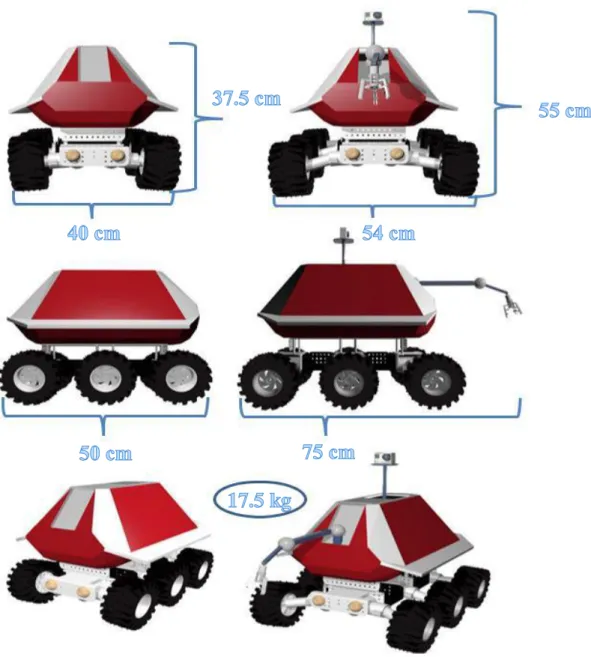
Figure 2.5 2D side views of robot………..………..…..12
Figure 2.6 3D side views of robot………..…………....13
Figure 2.7 Design (left side) and realization (right side) of robot……….14
Figure 2.8 Robot is at the initial position………..………...15
Figure 2.9 Position of the robot after rotation……….…...16
Figure 2.10 Position of the robot after rotation and translation……….….17
Figure 2.11 Schematic of the robotic arm………...18
Figure 2.12 Kinematics Calculations for the Arm………...…...19
Figure 2.13 Kinematics Calculations for the Arm (viewed from above)………...20
Figure 3.1 Block diagram of the system………..….……..…24
Figure 3.2 Arduino Mega ADK(2560) ………..26
Figure 3.3 Raspberry Pi with ports and other parts………..……….….27
Figure 3.4 Layer and bottom chassis details………..…………...31
Figure 3.5 View of the chassis………....31
Figure 3.6 Wheels and shaft………...32
Figure 3.7 IBT-2 and wiring diagram of IBT-2…….…….………...……...33
Figure 3.8 Open form of telescopic rod and linear motor....………...…………...33
Figure 3.9 Closed form of telescopic rod and linear motor………....34
Figure 3.10 Side and front view of robotic arm………...………...35
Figure 3.11 Pins of L293D (left) and connection template of robot arm (right)…………...36
Figure 3.13 Details of L298N………...…37
Figure 3.14 Suspension detail……….…..…39
Figure 3.15 Front view of suspension………...….39
Figure 3.16 Robot in testing environment………...……..…....41
Figure 4.1 Flow chart for operation of the robotic system………....…....43
Figure 4.2 Tabs of the movement codes……….….….………...…..44
Figure 4.3 Sub-codes which are called in the main code………...………....….45
LIST OF TABLES
Table 2.1 link parameter for a 3-link planar manipulator………..21 Table 2.2 link parameter of robot’s arm……….21
LIST OF ABBRAVATIONS / SYMBOLS
USAR Urban Search and Rescue
GPS Global Positioning System
LAN Local Area Network
USA United States of America
Kg kilogram
g gram
CAD Computer Aided Design
USB Universal Serial Bus
PWM Pulse Width Modulation
ICSP In-Circuit Serial Programming GPU Graphics Processing Unit
RAM Random Access Memory
GHz, MHz Giga hertz, Mega hertz
SD Storage Device
Mb Mega byte
2D, 3D 2 dimension, 3 dimension
CMOS Complementary Metal Oxide Semiconducter
I/O Input/Output
mm millimeter
cm centimeter
p pixel
LED Light Emitted Diode
A Ampere mA miliampere mAh miliampere-hour V Volt DC direct current GND Ground
AOUT Analog Output
CO Carbon Monoxide
RPM Revolution per minute
IP Internet protocol C capacitance 3G third generation θ theta α alpha sin sinus cos cosinus
{Xb,Yb} coordinate plane with respect to base frame {Xm,Ym} coordinate plane with respect to movement frame
P initial position
P’ position after rotation or/and translation dx displacement on x coordinate
dy displacement on y coordinate θs, θe, θw, θse joint rotations for robotic arm
rdist total distance between robotic arm base and gripper when gripper holds the object
U link length between shoulder and elbow of robotic arm L link length between elbow and wrist of robotic arm G link length between wrist and gripper of robotic arm
B the height between base and ground
Rot rotation matrix
Trans translation matrix
Ai homogenous transformation for link i
θi link angle for link i
ai link length for link i
di link offset for link i
αi link twist for link i
xf’ final position on x axis after transformation of robotic arm and robot yf’ final position on x axis after transformation of robotic arm and robot zf’ final position on z axis after transformation of robotic arm and robot
1. INTRODUCTION
Robotic is the branch of technology that deals with the design, construction, operation, and application of robots, as well as computer systems for their control, sensory feedback, and information processing. These technologies deal with automated machines that can take the place of humans in dangerous environments or manufacturing processes, or resemble humans in appearance, behavior, and/or cognition.
There is many different kind of catastrophe in natural and man-made disaster: earthquake, flooding, hurricane and they cause different disaster area like collapsed building, landslide or crater. During these emergency situations, especially in urban disaster, many different people are deployed such as policeman, fire fighters and medical assistance. They need to cooperate to save lives and evacuate victims to safe area. In these situations, human rescuers must make quick decisions under stress and take action for safety of victims. They must determine the location and status of victims and the stability of the structures as quickly as possible so that medics and firefighters can enter the disaster area and save victims.
All of these tasks are performed mostly by human and trained dogs, often in very dangerous and risky situations. Since recent decades, mobile robots of different sizes and capacities have been proposed and deployed to help them to detect victims and to identify potential hazards for rescuers [1].
For this project, we will focused on a mobile robot providing streams of video and other essential data via wireless connections to human operated base station, supplemented by various basic and optional behaviors on board of the robots which will work in a disaster environment of man-made structure, like collapsed buildings. Improved speed of operation is imperative to raise survival rate in such situations. The Robot is designed with the aim of carrying out speedy search and rescue operations at disaster sites. The primary scope of this project is to create a robot which will search and rescue victims that are difficult to reach by conventional search and rescue means.
1.1 Literature Review
From experiences of natural and man-made disaster in decades, mobile search and rescue robotic systems are replaced with humanitarian search and rescue systems due to insufficiency.
Urban search and rescue (USAR) robots are real life and application study since last decades. Unfortunate disasters in the past such as the Mexico City earthquake in 1985, the Oklahoma City bombing in 1995, and the September 11, 2001 World Trade Center are some of the tragedies show the need for robots in assisting for rescue workers in places that are not safe and reachable. In Mexico City earthquake, 135 rescue workers were killed, 65 of the 135 died while trying to search and rescue while going through confined spaces which were flooded trapping the rescue workers inside [2].
Terror attack on the World Trade Center (WTC) in the September 11, 2001 was the first known time where robots were actually used in a search and rescue effort. In the WTC, robots were used to explore unreachable spaces by delivering real-time photographic information from an environment unreachable and hostile both to the rescue workers and their trained dogs. This unfortunate event provided an opportunity to test the existing USAR robotic systems in real rubble piles, to explore the robot human interaction, and to define new requirements and mechanical needs from these systems. Numerous works related to USAR robots were published [3].
With the advancement in sensor miniaturizations and exponential increment in the speed and capability of microcontrollers, rescue robots small enough to thread through rubbles are rolling out of experimental laboratories into the catastrophic areas.
Rescue robotics features an interesting combination of allowing basic research while being application oriented [4]. The focus for the application oriented systems is on rugged, simple platforms that mainly act as mobile cameras [5][6]. On the other hand, any kind of intelligence in the sense of perception and world-modeling capabilities up to autonomy is very useful not only from a basic research but also from an application perspective. Researchers in the rescue community accordingly work on issues like mapping or fully autonomous victim detection [7] and navigation as well as exploration [8].
1.2 Major Research Challenges
Robotics for urban search and rescue has challenges that make it interesting from a research point of view. These challenges also make it a very difficult field commercially. The issues which USAR robots face are so numerous that the development of robots to do this task is so expensive that they are not commercially or practically viable. Issues such as the incredible variation of terrain that the robots need to navigate have created problems that are not easily
overcome. The solutions to the challenges are also what make an urban search and rescue robot unique when compared to more generic systems.
1.2.1 Locomotion
Locomotion system of search and rescue robots is important issue for researchers. Locomotion is incredibly varied due to landscape of the disaster areas. The terrain can be different types such as large chunks of concrete, to gravel or dust etc. Also, leaks from clean water and sewage pipes make extra difficulty by causing slippery surfaces and reducing traction of an area. To help researchers to prepare for these varied difficult environments, USAR robotics competitions have been started that utilize simulated rubble and situations to test and evaluate systems. Research is vast and varied in this specific area, from robots that use manipulators to move themselves [9], to systems that utilize a continuous membrane [10], to more common forms of locomotion like tracks or wheels. Reviews have been presented both on robot locomotion [11] and on locomotion for search and rescue specifically [12], but still the research community has not developed a robot that is achieved for all environments. Locomotion, mechanical design in the broader sense, will be a constraint factor in research and prove to be a major challenge at developing a robotic system that can handle any and all terrain.
1.2.2 Mapping and Localization
The challenge of mapping and localization are very important for this research. Searchers and rescuers need to mapping and localization to provide to form of a complete map of the environment and the ability to define the position of the robot relative to a landmark or the user. This is incredibly crucial due to the rescuers need to see the environment and create a safe possible rescue plan. The mapping gives the rescuers all the details about location of the obstacles. So that a trained professional will be capable to see what objects are holding the structure up and where potential weak points are. USAR robots have utilized a wide range of sensors for detecting the environment. Cameras are widely used in this field with single camera and with multiple cameras [13]. Researchers also focus on the algorithms required to make this intensive mapping computationally viable and work in real time [14]. The development of cheaper, more powerful processors will help these researches easier to cooperate with mobile robots.
1.2.3 Communication
Communication system of a robot can be divided in two main categories which are wired and wireless systems. Each communication category has advantages and disadvantages. An important advantage of wired (tethered) communication is to provide the ability to achieve lighter robots. This feature is important due to it cancels the requirement for on board power. This is beneficial in unstructured environments, because of the weight of the robot can cause slippage on rubble, or in an extreme case the collapse of the structure. A robot with tethered communication can also achieve a reliable communication channel with large bandwidth. This provides the robot very easy data and video transmission. The tether provides a life line by which the robot can be retrieved. Robin Murphy, an expert in the field of robots for urban search and rescue, is a major supporter of tethered systems [15]. Wireless communications or tether less systems have the advantage as they are not restricted by a cable which means they can enter environments without the fear of a tether can be caught on rubble. While tethered robots have a reliable communications, they also have the disadvantage of the tether is also a vulnerability for the robot. If the tether is damaged or destroyed the robot is lost. With wireless system the communications the robot is only restricted by the connection to the user.
From an implementation point of view, tethered is the easiest and most reliable system for an urban search and rescue robot. However, a tether less system would provide far better functionality for the application. There is division between researchers over the best type of communications for these robots.
1.2.4 Human and Robot Interaction
Final major challenge for search and rescue robots is human and robot interaction. This challenge is due to artificial intelligence is still not developed to allow robots to work autonomously. Robots are still need to cooperate with the human operator for the operations, making decisions and interpreting data. The primary requirement to make human and robot interaction effectively is an easily understandable and operable an interface. The interface must provide all required data while sustaining clear and concisely. So human operator, user must to control the robot through an interface.
Different types of interfaces are already being used by researchers. Some of them have used gaming technologies such as Xbox 360’s Kinect, to provide video interface [16]. This technology is not directly aimed for robotics but it can be used in robot control applications.
Other research for human and robot interaction that researchers work on is brain-computer interface [17]. This research provides disable people to control machines by only using their own thoughts. Recently, a research show a woman has robotic arm can control it with this device [18]. These researches force human robot interaction to have a bound. Researchers require an interface system which is simple to use, easy to run. System must also work in hazardous, cluttered environments and it must be reliable in these conditions.
1.3 Background of the Research
İstanbul Bilgi University has developed a mobile guide robot which is called RoboSantral. Aim of the robot is to welcome and guide to visitors at university campus. As robot guides the visitors and new coming students it also shares related information about its campus and museum of historical power plant. When the visitors desire to go to a specific location in the university, RoboSantral takes them there and gives the related info along the way. The robotic system is composed of many diverse components such as, Arduino microcontroller and raspberry Pi, sensors, GPS unit, loudspeakers, display systems and a robotic motion kit etc. [19]. Robosantral understands its location by processing information that is taken from GPS sensors. Image processing system is also developed to find out the targeted destinations. When robot arrives to the destination, it informs the visitors about the buildings and labs etc. by sharing some video and audio data via its loudspeakers and display unit. Arduino and raspberry Pi work simultaneously for controlling the robot [19]. Although this robotic system is designed for guidance, working principle of control and locomotion system can help us on research.
İstanbul Bilgi University also developed a mobile air quality and pollution measurer robot which is called Ventus. Aim of the robot is to measure the air quality and pollution at outdoor environments and send data via a wireless communication to operator. Ventus is equipped with similar control and locomotion system components with RoboSantral like as Arduino, raspberry Pi, sensors, loudspeakers etc. Controlling motors and sensors is achieved by Arduino microcontroller and controlling camera, loudspeakers and providing internet connection is achieved by Raspberry Pi for the robot [20]. Ventus has also telescopic probe which enables a platform for GPS and other additional sensors to be placed on it [20]. Telescopic probe moves to outside of the robot to measure air condition of a desired place. This robot is not developed for same purposes with research, however operating principle, functions and mobility features can easily be adapted for urban search and rescue robotic.
Figure 1.1 Robosantral (left) and Ventus (right) in Bilgi University Campus [19][20] University of Minnesota has developed an inspection system that is called ranger and scout for search and rescue team. System has small scout robots inserted in ranger robot carries them. Ranger robot can deploy scout robots to search area from the upper platform on the top of it. Scouts are specialized robots that carry out low-level, usually parallel tasks aimed to meet the mission objectives. This system is also available for multiple scouts to be launched from different number of deployed rangers. Communication of robots with each other is achived over a 2.4 GHz frequency-hopping wireless LAN system [21]. The system is designed for searching system but can be adaptable for urban search and rescue operations.
Figure 1.2 Ranger robots (right) and Scout (left) robot [21]
Active scope represents a very different approach for search and rescue robotic. The system allows the ability to enter the smallest possible holes and show victims and damages in disaster area for search and rescuers. It utilizes ciliary vibration as its motion mechanism. Active scope uses small inclined rods, or cilia, that are vibrated inducing motion. The
operator can control the direction by moving the head of the scope through the desired direction. Active scope provides good mobility in disaster areas, but its performance is not efficient enough in terrains without walls to provide movement surface [22]. Although the system is effective for inspection, it has disadvantages in range and functionality.
Figure 1.3 Active scope and operator [22]
iRobot is a commercial robotics company founded in Massachusetts, USA, in 1990. The company has created the Packbot 510 and Warrior 710 robots. These robots have a tracked wheel system for mobility and locomotion with the added controllable tracked arms. These arms provide the robots perfect utility to move in obstacles, like rubbles or stairs. The robot can achieve traction and stability readily on slopes by directing and moving its tracked arms. This solution is really effective at moving on rubbles and climbing stairs [23][24]. This feature can be applicable for USAR robots. The tracked locomotion system allows the robots to mobility over loose surfaces like pebble or sand dune with ease. The robots also have robotic arm that provide interaction between operator and the environment. They can lift up to 13,5 kg with its manipulator [23]. The end effector force is transmitted to the operator providing to determine if manipulator is grasped an object or not. These robots have been satisfied for search and rescue operation and they are deployed in disaster areas such as Japan earthquake and Fukushima Nuclear Plant for different duty.
Figure 1.4 Packbot 510 (left) and Warrior 710 (right) robots [23],[24]
Tohoku University and Chiba Institute of Technology has developed a robot technology that is called Quince. Like many of the other robots, Quince utilizes tracked wheel system for locomotion. It has used very similar design with Packbot from iRobot company, however, it differs in two main feature. The first one is that Quince robots has no robotic arm which means it cannot directly interact with the environment in same capacity. Secondly, Quince’s locomotion system has three tracked part. It has also front and rear tracked arms. These arms are controlled independently controlled and give robot six degrees of freedom [25]. The arms provide robot to maintain stability and also they can be used to increase the overall length of the robot to bridge over wider spaces [25]. Quince also has a 3D scanner system that is called TK scanner. It utilizes a 2D laser range finder on a pan-tilt platform [26]. The Quince robot has the ability to map the physical environment of the disaster area with TK Scanner.
2. VISUAL DESIGN AND MODELING
2.1 Visual Design
CAD design has the vital importance due to building a robot according to design, provides convenience about modeling and gives opinion about its appearance. For that reason, different two and three dimensional design programs are used during the project.
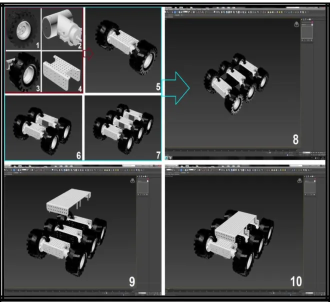
Firstly, wheels, wheel system and chassis are designed step by step according to planned materials which are used. The motion platform is built on chassis and material platform which includes six free wheels. It is chosen to design and build a special purpose motion platform in order to keep robot in balance on rough and uneven terrains with obstacles instead of using a multi-purpose ready-made platform.
The chassis is made from thick aluminum but robot platform is made from thinner aluminum, because chassis must be heavier than robot platform in order to provide the exact balance while it is moving. Another reason for using aluminum is to provide durability to the robot. For giving aluminum view, grey and red aluminum materials were used.
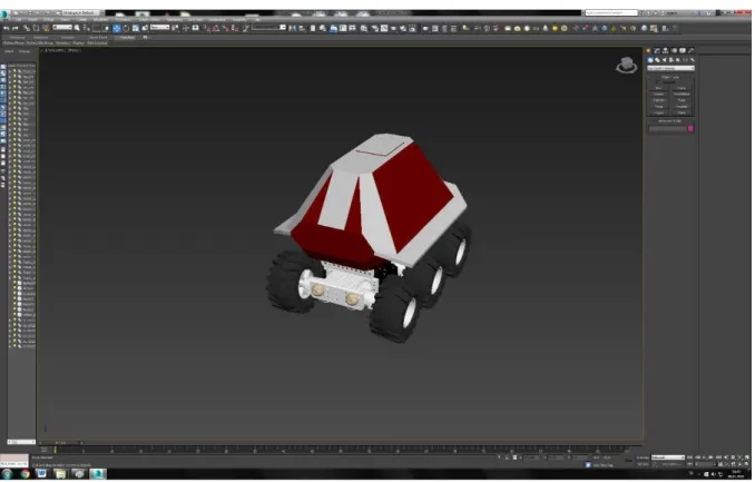
After body design, body and chassis of the robot are combined. CAD design of robot with body and chassis are shown in Figure 2.2
Figure 2.2 View after body and chassis are combined
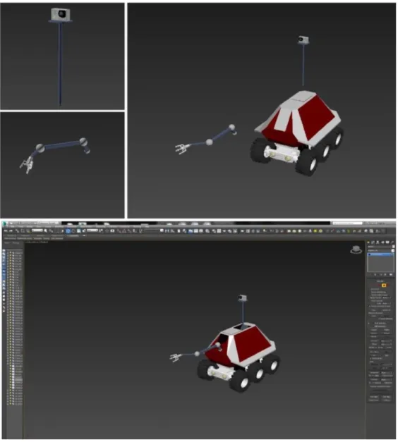
The robot is designed to have collapsible tools. The first tool is camera which is shown up with telescopic rod from top of the robot and the second tool is robotic arm which goes out front of the robot.
The robot arm and camera are designed in 3ds Max. They are fitted into robot with mechanical materials. Giving a nice appearance is not only reason for choosing this shape and color. Placing electronic parts, mechanical parts and collapsible tools into the robot properly is one of these reasons.
Figure 2.3 Design with telescopic rod and robotic arm
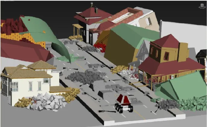
Animation is significant to see and show our robot’s capability in a symbolic area. The animation of the robot is created by 3ds Max design software.
First step was creating the earthquake environment. Various tumbledown house figures are used to give earthquake effect and these figures are placed on the road figure step by step. Other environmental figures are added to give earthquake effect to create the earthquake area for animation. Obstacles are created to show robot’s ability of overcoming obstacles.
After the design of the earthquake environment, animation was created with the appropriate commands of 3ds Max. Finally, the robot is merged to the disaster area.
Figure 2.4 Robot in disaster area
Figure 2.6 3D side views of robot
2.2 Cad Design to Mechanical Design
After non-physical parts which are design and animation, the realization stage of the robot is started. The robot is built by using proper materials according to CAD design and these materials are assembled step by step.
Firstly, the wheels and suspensions are selected and built based on three reasons; 1. Should keep robot in balance
2. Enough to carry the weight of robot
Chassis is built a little differently from the design because it should be more complex and suitable for real living conditions. The wheels and suspensions are placed on chassis. In this stage, some holes are made in chassis for cables and linear actuator.
For body shell, a shape is made according to CAD design. The materials which are used in body shell are selected according to similar reasons mentioned above and it should have enough area inside itself for electronic tools and other materials. Also, some holes are made in body for robotic arm, sensors, linear actuator and etc.
In painting stage, the important point is that colors should be the exact same with design and realization. These colors are selected to make robot remarkable, visible and easily detectable in disaster area. Therefore, these dark red and grey colors are obtained by mixing some colors. Thus, chassis and body shell are painted with these colors.
After painting, chassis and body shell which are built separately are assembled. Lastly, collapsible tools, electronic tools and other materials are placed in robot.
The final look of robot shows up. Consequently, the robot is realized which is quite similar to CAD design. Figure 2.7 shows that the stages of robot from design to realization.
2.3 Mathematical Modeling
Mathematical modeling of transform of the robot and robotic arm are expressed in this part of the thesis. Kinematics is used for mathematical calculations of motion without considering the forces that affect the motion.
By kinematics, we can focus on
the geometric relationships that govern the system,
relation between control parameters and behavior of a system in state space.
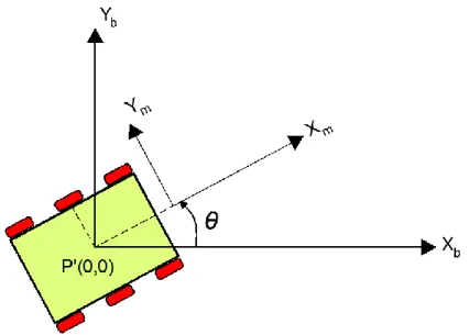
The robot is initially assumed at the base position, the rotation position with “θ” angle on base position and the final position with respect to “θ” angle and (x,y) are the points at coordinate plane. {Xb,Yb} refers to coordinate plane with respect to base frame and {Xm,Ym} refers to coordinate plane with respect to moving frame.
Figure 2.8 Robot is at the initial position
We assume the robot is immobile at (0,0) point which respects initial points in coordinate system as shown figure 2.8 above. We assume firstly robot will rotate on initial point and then robot will move at moving frame.
Figure 2.9 Position of the robot after rotation
Then the robot rotates on base frame with “θ” angle. But it is still at same points on coordinate plane. P = 1 y x
matrix shows the robot posture in base frame.
P’ = 1 ' ' y x
matrix shows the robot posture after rotation and/or translation.
1 ' ' y x = 1 0 0 0 cos sin 0 sin cos 1 y x (1.1)
Rotation matrix formula is given eq 1.1
1 ' ' y x = 1 0 0 1 0 0 1 y x d d 1 y x (1.2)
Translation matrix formula is given eq 1.2 where dx is displacement on x axis and dy is displacement on y axis.
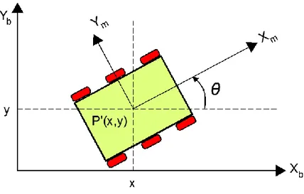
Figure 2.10 Position of the robot after rotation and translation
Finally the robot moves to P(x,y) position through on moving frame with respect to “θ” angle.
Now we can calculate transformation of the robot with respect to rotation matrix (eq 1.1) and translation matrix (1.2).
Transformation = Translation ● Rotation
1 ' ' y x = 1 0 0 1 0 0 1 y x d d 1 0 0 0 cos sin 0 sin cos 1 y x (1.3) 1 ' ' y x = 1 0 0 cos sin sin cos y x d d 1 y x
Robot Arm Modeling
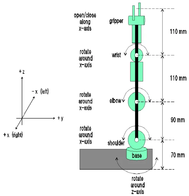
The arm has four rotational joints which are called base, shoulder, elbow and wrist. The base rotates the arm around the vertical z-axis, while the other three rotate it around the x-axis. No joint rotates around the y-axis, which limits the arm's movements but also makes the kinematics calculations much easier. Each joint has a rotation limit, in the backwards and forwards directions for the wrist, elbow and shoulder, and to the left and right for the base. The arm's gripper opens and closes via rotating gearwheels, but its prongs are connected to
the wheels in such a way that they stay roughly parallel to each other as they move. Since the gripper's movement is so restricted, it is not treated as a joint.
Figure 2.11 Schematic of the robotic arm
We can calculate an endpoint position such as location of wrist, gripper or an object that is desired to be hold by robotic arm. Forward kinematics will help us to calculate endpoint positions by using joint rotations of the arm. The mathematical model is shown by Figure 2.12.
Figure 2.12 Kinematics Calculations for the Arm
The joint rotations are known for the base (θb), shoulder (θs), elbow (θe), and wrist (θw).
(x, y, z) coordinates are obtained at the top of the object.
Calculation is started by (rdist, z), where rdist is the shortest distance from the arm to the object. From Figure 2.12, the coordinate values are:
rdist = Usinθs + Lsinθse + G (2.1)
z = B + Ucosθs – Lcosθse (2.2)
where θse = 180 – (θs +θe) and U, L, and G are the lengths of the upper arm, lower arm, and
gripper links respectively. Due to fixing of the wrist-gripper link to always be horizontal, there's no need to employ the wrist angle (θw).
Figure 2.13 Kinematics Calculations for the Arm (viewed from above)
The distances are:
x = rdistsin(θb) 2.3
y = rdistcos(θb) 2.4
Mathematical Modeling of Robot Arm with Denavit-Hartenberg Convention
A commonly used convention for selecting frames of reference in robotic applications is the Denavit-Hartenberg or DH convention. In this convention, each homogeneous transformation Ai is represented as a product of four basic transformations
A
i = Rotz,θi,
Transz,di,
Transx,ai,
Rotx,αi (3.1)= 1 0 0 0 0 1 0 0 0 0 cos sin 0 0 sin cos i i i i 1 0 0 0 1 0 0 0 0 1 0 0 0 0 1 i d 1 0 0 0 0 1 0 0 0 0 1 0 0 0 1 ai 1 0 0 0 0 cos sin 0 0 sin cos 0 0 0 0 1 i i i i
A
i = 1 0 0 0 cos sin 0 sin sin cos cos cos sin cos sin sin cos sin cos i i i i i i i i i i i i i i i i i d a a where the four quantities ai, αi, di, θi, are parameters associated with link i and joint i. The
four parameters ai, αi, di and θi in (3.1) are generally given the names link length, link twist,
link offset, and joint angle, respectively.
Table 2.1 Link parameters for a 4-link planar manipulator
Table 2.2 Link parameters of robot’s arm
Table 2.1 shows link parameter for a 4-link planar manipulator and Table 2.2 shows link parameter of robotic arm where link numbers 0, 1, 2, 3 represent robot’s links between base-shoulder, shoulder-elbow, elbow-wrist and wrist-gripper respectively. Links of our robotic arm as shown in figure 2.12 is like 4-link planar manipulator which is shown in table 2.2. Thus, α0 = 90, α1,2,3=0 and ai=0 Link ai αi di θi 0 1 2 3 a1 a2 a3 a4 α1 α2 α3 α4 d1 d2 d3 d4 θ1 θ2 θ3 θ4 Link ai αi di θi 0 1 2 3 0 0 0 0 90 0 0 0 B U L G θb (90-θs) θe θw
for link0, A0 = 1 0 0 0 1 1 0 0 sin 0 sin 0 sin 0 cos B b b b b where d0=B and θ1=90-θs for link1, A1 = 1 0 0 0 1 0 0 0 0 ) 90 cos( ) 90 sin( 0 0 ) 90 sin( 90 cos( ) U s s s s where d1=U and θ1=90-θs
since cos(90-θs) = sinθs and sin(90-θs) = cosθs
A1 = 1 0 0 0 1 0 0 0 0 sin cos 0 0 cos sin U s s s s for link 2, A2 = 1 0 0 0 1 0 0 0 0 ) cos( ) sin( 0 0 ) sin( ) cos( L e e e e where d2=L and θ2= -θe
since cos(-θe) = cos(θe) and sin(-θe) = -sin(θe)
A2 = 1 0 0 0 1 0 0 0 0 cos sin 0 0 sin cos L e e e e for link 3, A3 = 1 0 0 0 1 0 0 0 0 cos sin 0 0 sin cos G w w w w where d3=G and θ3= θw
A=A0A1A2 A3 (3.2) A= 1 0 0 0 1 1 0 0 sin 0 sin 0 sin 0 cos B b b b b 1 0 0 0 1 0 0 0 0 sin cos 0 0 cos sin U s s s s 1 0 0 0 1 0 0 0 0 cos sin 0 0 sin cos L e e e e 1 0 0 0 1 0 0 0 0 cos sin 0 0 sin cos G w w w w
Robot transformation can be calculated by DH convention but it would be complex and hard to combine modeling body and manipulator of robot. For that reason, equations (1.3), (2.1), (2.2), (2.3) and (2.4) are used for modeling final transformation of robot. But, we assume equation (1.3) as three dimension.
1 ' ' ' f f f z y x = 1 ' ' ' z z y y x x (4.1)
where x’, y’, z’ are transformation of robot body and x, y, z are transformation of manipulator and xf’, yf’, zf’ are final transformation of robot.
from equations (2.1), (2.2), (2.3) and (2.4), respectively rdist = Usinθs + Lsinθse + G
x = rdist sin(θb) y = rdist cos(θb) z = B + Ucosθs - Lcosθse 1 ' ' ' f f f z y x = 1 )] cos ( cos ( [ ] cos G) + sin L + sin U [( ' ] sin G) + sin L + sin U [( ' ) se s se s se s b b L U B y x
3. SYSTEM OVERVIEW
Overall system design includes four main blocks which are input, control, locomotion and output and communication blocks. Raspberry Pi 2 and Arduino Mega are used in the system as controller unit. All three blocks are connected to controller block as shown in below figure 3.1
Components of input block collect the environmental data like temperature, visual information, sound, air condition and send them to controller block. Controller block take data and make some data process. It always has interactions with other three blocks. Then it communicates with the server through a wireless network and stores data in database. Result of all of the process, locomotion and output block take various actions by its components.
3.1 Controller Block
Controller block is the unit that controls all components in the system and implements interaction between blocks. It consist Arduino Mega ADK (2560) and Raspberry Pi as small computer. Arduino can be controlled by its own open source programmable software and Raspberry Pi is a credit card sized single-board computer. Control units take and process environmental data from input block and tells locomotion and output block to take various actions. When we consider its function it can easily said that controller block is brain of the system.
3.1.1 Arduino Mega
Arduino is a tool that can sense and control more of the physical world than a desktop computer. It's an open-source physical computing platform based on a simple microcontroller board, and a development environment for writing software for the board. Arduino can be used to develop interactive objects, taking inputs from a variety of switches or sensors, and controlling a variety of lights, motors, and other physical outputs. Arduino projects can be stand-alone, or they can communicate with software running on your computer. The Arduino programming language is an implementation of wiring, a similar physical computing platform, which is based on the processing multimedia programming environment.
The Arduino ADK that is used in the system is a combination of hardware and software designed for many purposes. It is introduced as board based on the Arduino Mega 2560 which includes USB host. It has a library that enables data to be sent and received from any external devices. The Arduino Mega is microcontroller board based on the ATmega2560 (datasheet). It has a USB host interface to base on the MAX3421e IC. It has 54 digital input/output pins (of which 15 can be used as PWM outputs), 16 analog inputs, 4 UARTs (hardware serial ports), a 16 MHz crystal oscillator, a USB connection, a power jack, an ICSP header, and a reset button.
About the Mega ADK board: The Mega ADK board is a derivative of the Arduino Mega 2560. The modified Mega 2560 board includes a USB host chip. This host chip allows any USB device to connect to the Arduino. The USB host is not part of the original core of Arduino. To use the new features on this board we need to include some libraries in our sketches.
There are two libraries needed to make the system work:
MAX3421e: handles the USB host chip
USB: handles the USB communication
Figure 3.2 Arduino Mega ADK (2560)
Arduino has vital duties for robot in the center of the controller block. It considerably provides convenience for controlling and programing of robot’s functions due to simplicity for uses and it already has a prosperous and sufficient library for itself. Arduino is used for programing gas and sound sensors in the system. It also provides us to control and program operational functions such as movement, rotation of robot and actions of robotic arm and telescopic rod. Different motors are used for various operational functions in the system. Each motor has driven over motor drivers which are controlled and programmed by Arduino. 5V DC and 1A power bank which is independent from main power supplies of motors is used as power supply for Arduino Mega. The main goal of the separation of the power supplies is due to motors need much more power for working so that Arduino is not desired to face with power failure to not affect the controller block.
3.1.2 Raspberry Pi
The Raspberry Pi is a credit-card sized computer that plugs into a computer monitor or TV, and uses a standard keyboard and mouse. It is a capable little device that enables people of all ages to explore computing, and to learn how to program in languages like Scratch and Python. It’s capable of doing everything that expect a desktop computer to do, from browsing the internet and playing high-definition video, to making spreadsheets, word-processing, and playing games.
The Raspberry Pi has a Broadcom BCM2835 system on a chip (SoC), which includes an ARM1176JZF-S 700 MHz processor (The firmware includes a number of "Turbo" modes so that the user can attempt overclocking, up-to 1 GHz, without affecting the warranty), Video Core IV GPU, and originally shipped with 256 megabytes of RAM, later upgraded to 512mb. It does not include a built-in hard disk or solid-state drive, but uses an SD card for booting and long-term storage.
The Raspberry Pi has the ability to interact with the outside world, and has been used in a wide array of digital maker projects, from music machines and parent detectors to weather stations with infra-red cameras.
Raspberry Pi is the other control unit which is used in controller block of the system. Raspbian, Debian based operating system, is used as operating system for Raspberry Pi. It selected because it is already official operating system of Raspberry Pi and easy to understand and work with. Raspberry Pi provides us to gather environmental visual data from thermal camera and CMOS camera via MPlayer and FLIR Kit. It also bridge over between operator and robot by connection with wireless internet connection. The robot is not autonomous which means it cannot move by itself in disaster area and both thermal. So CMOS cameras are like eyes of the operator. When we consider about this point of view, Raspberry Pi has a vital duty for controlling of the robot by operator due to it provides communication and visual environmental information for operator. So it must work uneventfully in the system. Internet access for the robot is achieved by Ethernet cable between modem and robot. This facility provides us high visual resolution with high data transfer rate.
3.2 Input Block
Input block collects the environmental data and makes robot to understand different types of environmental data using sound and gas sensors and CMOS and FLIR cameras inside and outside the robot. These sensors and cameras provide information gathering capability to robot. Also it provides visual data transmission that is taken by cameras from environment to the system.
3.2.1 Cameras
The visual information is obtained from thermal (FLIR Kit) and CMOS (Raspberry Pi) camera units. There is led illumination for operation in dark environments. Thermal camera enables detection of the survivors by their body temperature. The use of both cameras is sufficient for visual detection of victims. Cameras are connected to Raspberry Pi 2. Thermal camera is connected to General I/O port of the Raspberry Pi and the CMOS camera is connected to the camera input that is already available. Therefore, single board operation is possible.
3.2.1.1 CMOS Camera
The Raspberry Pi Camera Module is a custom designed add-on for Raspberry Pi. It attaches to Raspberry Pi by way of one of the two small sockets on the board upper surface. The board
itself is tiny, at around 25mm x 20mm x 9mm. It also weighs just over 3g, making it perfect for mobile or other applications where size and weight are important. It connects to Raspberry Pi by way of a short ribbon cable. The camera is connected to the BCM2835 processor on the Pi via the CSI bus, a higher bandwidth link which carries pixel data from the camera back to the processor. This bus travels along the ribbon cable that attaches the camera board to the Pi. The sensor itself has a native resolution of 5 megapixel, and has a fixed focus lens onboard. In terms of still images, the camera is capable of 2592 x 1944 pixel static images, and also supports 1080p30, 720p60 and 640x480p60/90 video.
3.2.1.2 FLIR Camera
FLIR cameras are excellent for detecting people, objects and incidents from dark to sunlit areas and other challenging conditions. However thermal cameras do not deliver images that allow reliable identification. That is why thermal camera and conventional camera complement and support each other in a surveillance installation. FLIR Dev kit for Raspberry Pi 2 is used as a thermal camera in robot.
The visual data can be seen on “Raspberry Pi touch screen” that is used to see the thermal camera vision. It is a 800×480 pixel touch screen suitable for use with Raspberry Pi 2.
3.2.2 Sensors
3.2.2.1 Gas Sensor
There 4 leads are +5V, AOUT, DOUT, and GND. The +5V and GND leads establishes power for the alcohol sensor. The other 2 leads are AOUT (analog output) and DOUT (digital output). How the sensor works is the terminal AOUT gives an analog voltage output in proportion to the amount of methane the sensor detects. The more methane it detects, the greater the analog voltage it will output. Conversely, the less CO it detects, the less analog voltage it will output. If the analog voltage reaches a certain threshold, it will send the digital pin DOUT high. Once this DOUT pin goes high, Arduino will detect this and will trigger the LED to turn on, signaling that the methane threshold has been reached and is now over the limit. The methane sensor circuit is built with an MQ-4 sensor integrated with an Arduino is shown below.
The connections are pretty basic. To connect the sensor, there are 4 leads. 2 of them are for power. The +5V terminal of the sensor connects into the 5V terminal of Arduino board. The GND terminal of the sensor connects into the GND terminal of the Arduino. This establishes power for the sensor.
The other 2 connections are the analog and digital output of the sensor. These connect to analog pin A0 and digital pin D8, respectively.
3.2.2.2 Sound Sensor
A ready module is used for sound detection of the robot. Sound sensor senses the distress call of the victim. It is connected to the robot arm and controlled by Arduino. Robotic arm makes noise while working and thus the light turns on.
3.3 Locomotion and Output Block
The Robot has a wheeled locomotion mechanism which will enable it to travel on rough and uneven terrains with ease. Its mobility is to be complemented with manipulation which enhances its capability to look for victims. An ultrasonic probe is driven by this robot arm in order to search under rubbles. The R-R robot arm will enable it to interact with its environment and remove rubble and obstacles when necessary. Visual information and complementing sensory information will be communicated to the human operators.
Locomotion and output block is built on chassis. All parts of the robot in this block are mounted on chassis. Chassis has robot wheels, motors, balance system, robotic arm, telescopic rod, batteries and some mechanical components. It consist an internal framework that supports a manmade object in its construction and use. It is analogous to an animal's skeleton. An example of a chassis is the under part of a motor vehicle, consisting of the frame (on which the body is mounted).
Figure 3.4 Layer and bottom chassis details
Figure 3.5 View of the chassis
3.3.1 Motors
DC motors are used for wheels. A DC motor is any of a class of electrical machines that converts direct current electrical power into mechanical power. The most common types rely on the forces produced by magnetic fields. Nearly all types of DC motors have some internal mechanism, either electromechanical or electronic to periodically change the direction of current flow in part of the motor. Most types produce rotary motion; a linear motor directly produces force and motion in a straight line.
DC motors were the first type widely used, since they could be powered from existing direct-current lighting power distribution systems. A DC motor's speed can be controlled over a wide range, using either a variable supply voltage or by changing the strength of current in its field windings.
There are 2 types of DC motors. It used reducer DC motor in the robotic system. Reducer is the system which is combined of the components like gears, bearing etc. DC motors are preferred in robotic systems. DC motors have a lot of advantages. These advantages are;
DC motors have more variety like speed, power, size etc.
DC motors are cheap.
It is easy to provide the DC motor.
DC motors can operate at low currents.
3.3.2 Wheels
Wheels of robot are shown in Figure 4.6 is used. Each wheel have 6mm shaft. Rotation is produced by the reducer shaft that transmits to the wheels.
Figure 3.6 Wheels and shaft
IBT-2 motor shield is used for movement of the wheels in the locomotion system. Its properties are like that; input voltage is 6V-27V, maximum current is 43A and input level is 3.3V-5V. Connection template is demonstrated below.
3.3.3 Telescopic Rod
A linear motor is an electric motor that has had its stator and rotor "unrolled" so that instead of producing a torque (rotation) it produces a linear force along its length. However, linear motors are not necessarily straight. Characteristically, a linear motor's active section has ends, whereas more conventional motors are arranged as a continuous loop.
The camera will move up with the linear motor. It works with 12V DC. Motor is taken 1.2mA. It can be opened up to 20 cm. Thermal camera and CMOS camera mounted on telescopic rod and telescopic rod carries them.
Figure 3.8 Open form of telescopic rod and linear motor
Same motor shield with wheels (IBT-2) is used for up and down movement of telescopic rod.
3.3.4 Robotic Arm
The robot arm was received ready but some of the plastic parts of the robot were converted to metal. For example, the robot has plastic gears but robot gears are converted to metal by mechanist so that the arm is stronger and longer. Robotic arm has five motors with gear boxes, the Edge has five degrees of freedom. 120 degree movement of the robot is able to move the wrist up and down. The bracket section of the arm is movable back and forth 300 degrees. The floor portion of the lever can be rotated 270 degrees and the floor joint bracket is movable back and forth by 180 degrees. And gripper has 0-4.5 cm distance for gripping motion. In this way, the robot's vertical reach 38 cm and 32 cm horizontal distance/work area provides. Besides, the robot arm removes weight 100g.
When one of the motor gearboxes encounters an excessive resistance to motion, the gearbox makes a noise that alerts us, so we stop the arm’s motion in that direction. Illuminating whatever the gripper is holding, a white LED is mounted to the hand of the arm.
Figure 3.10 Side and front view of robotic arm Arm Features;
There is a wired control arm but we will not use it
The robot gripper is collapsible
The wrist of the arm is 120°
The bracket of the arm move 300°
The floor portion of the lever can be rotated 270°
The floor joint bracket is movable back and forth by 180°
Installation is performed easily and it does not require soldering
The wired remote control is cancelled in the robotic arm and robotic arm is controlled with remote control. L293D (integrated motor driver) is used and built integrated circuit. Connection template is demonstrated figure 3.11. L293D is preferred because robotic arm motors work with 6V.
Figure 3.11 Pins of L293D (left) and connection template of robot arm (right)
3.3.5 Robotic Arm Sliding Mechanism
There are 2 gears for robotic arm’s sliding mechanism. The first gear is rack gear. The second gear is spur gear. Spur gears and racks work together. Rack gear is moved by spur gear. In this way arm goes inside and it goes outside. 12V 30 RPM motor is being used for this mechanism. It is controlled by the remote control.
Figure 3.12 Robotic arm’s sliding mechanism
L298N is used for Robotic Arm’s sliding mechanism. L298N properties are like that; two separate motors can be controlled independently, output current per channel is 2A, double H-bridge motor driver, L298 motor driver integrated, 2 DC motors can be two-directional control, built-in 5V voltage regulator and driving voltage of 5V-35V.
Figure 3.13 Details of L298N
3.3.6 Power Supplies
Power management is the biggest challenge for such big and heavy robots. In robot 3-cell 11.1v Lithium Polymer batteries with 22,000mAh power were used in order to supply power
to Locomotion and Output block. The control block and communication block are powered with Power Banks with 4000mAh power. On-Off button is connected between LiPo batteries and locomotion output system in order to prevent power loss when power is not required. This button helps users for easy opening and closing. It is placed on the corner of chassis in order to provide accessibility.
3.3.6.1 Lipo Batteries
LiPo batteries (short for Lithium Polymer) are a type of rechargeable battery and they are generally used in electronic devices like laptops, cell phones, mp3 players or etc. Although their small sizes they can provide high power and this makes them also usable for such robots. They are made up of cells and only one cell has 4.2V capacity. Their cells may be connected parallel or series. They are named according to their cell’s connection types.
For example; if a 3 cell battery is connected in series it is called 3S, if connected in parallel it is named 3P. They also has a capacitance value shortened by C. The capacitance value tells the power supplying capacity of a LiPo battery per one hour. In SALVOR 3S 22,000mAh LiPo batteries were used for Locomotion and Output block.
3.3.6.2 LiPo Charging
While balance charging LiPo batteries, two parameters to be considered are charge current and charge voltage. Charge Current is the current at which you should charge your LiPo battery depending on the battery's capacity and charge C rating. Regardless of charge C rating, charging LiPos at 1C is the safest rate, both from a fire danger and battery longevity standpoint. Charging LiPo at a higher rate will make it charge faster, but charging at high rates will also decrease the life of the battery in the long run. Charge Voltage is the nominal voltage of the battery that wanted to charge in. The charger states the cell arrangement (such as "3S") next to its nominal voltage for easier recognition.
3.3.6.3 Power Banks
Two power banks are used to supply power the communication block and control block. The output voltage of power banks is 5V DC and 1A. Using power bank is the optimal solution for Raspberry Pi 2 and Arduino because they are suitable with their output values and their durability.
3.3.7 Suspension System
Suspension is the system of tires, tire air, springs, shock absorbers and linkages that connects a vehicle to its wheels and allows relative motion between the two. Suspension systems serve
a dual purpose contributing to the vehicle's road holding/handling and braking for good active safety and driving pleasure, and keeping vehicle occupants comfortable and a ride quality reasonably well isolated from road noise, bumps, vibrations etc. These goals are generally at odds, so the tuning of suspensions involves finding the right compromise. It is important for the suspension to keep the road wheel in contact with the road surface as much as possible, because all the road or ground forces acting on the vehicle do so through the contact patches of the tires. The suspension also protects the vehicle itself and any cargo or luggage from damage and wear.
Figure 3.14 Suspension detail Figure 3.15 Suspension front view
What is the purpose of the suspension?
To reduce the vibration from the various components of the robot.
Keep the robot stable to wobble and bounce when it move.
There is bound to suspension bedding and articulation to connect suspension. Articulation is the mechanical system providing the connection without losing the ability to move the two parts moving features. Suspension system is carried out with the objective of robust locomotion and dexterous manipulation capability. It is compact enough to enter confined spaces, robust enough to move over obstacles in cluttered environments and maneuverable enough to crawl into mazes of collapsed roads and buildings. The robot makes a difference by entering disaster sites which are too hazardous for human being.
3.4 Communication
Communication through a wireless link is vital for control of the robot. Video and sensor information are processed partially on the robot itself but the main control is at the user side.
Therefore, our main goal is to provide infallible transmittal of visual and control information through the communication block in full-duplex method.
The video information is taken from two different cameras with different resolutions; thermal camera (FLIR Kit) with resolution 80x60 pixel, whereas the resolution of the CMOS camera can be as high as 1920x1080 pixels. This visual camera information is required to be transmitted simultaneously to the user via wireless link. The wireless link is also used for controlling the robot and receiving the sensor information of the robot. Therefore, the wireless link must have a high bandwidth capability. Dual channel wireless N communication protocol is planned to be used in robot for maintaining long distance and high data rate at the same time. In the case of tough environments, dual link is added to the design plans. This dual link consists of separate transmission of visual and control signals.
MPlayer is used as visual transfer interface to provide communication between robot and human operators. MPlayer provides the least possible latency on camera streaming.
To work with MPlayer we need; o
Raspberry Pi 2 o
TP-Link Modem o
Raspberry Pi Camera Module o
Ethernet Cable o
SD card
Raspberry Pi Camera module comes with built-in environment for Raspberry pi 2. That is why it gives the highest possible definition which is 1080px. A local network is created to provide communication between computer and raspberry pi. This communication is supported with 3G internet which is provided by a mobile phone. Once we have the communication, we tell to computer with a command “netcat” to listen the raspberry pi 2 for possible incoming visual data. After that, we tell to Raspberry Pi with a command “cat video” to send the visual data to a known IP address which is same IP address of the computer. Eventually, MPlayer window pop up and then we are able to follow the robot through any environment.
The reason MPlayer is preferred, It has been tried the other platforms which are Gstreamer and motion etc. However, we have realized that the best way for camera streaming in terms of latency and high quality is MPlayer.
Also 6 channel RC transmitter remote controller is used in order to control robot. The controller has 6 channel 2.4 GHz radio systems with telemetry capability. This radio system uses a high gain and high quality multi directional antenna, it covers the whole frequency band. Associated with a high sensitivity receiver, this radio system guarantees a jamming free long range radio transmission. It is easly programmable and suitable for use with Arduino.
3.5 Operation Testing
The process from design to realization for robot was truly tough challenge for us, because we had limited time for realization of research. Consequently testing and operation is the crucial stage for the research. The robot was tested in an arena which simulates the disaster zone. The testing environment consists of,
Doll for simulation of victim
Narrow mazes which is hard to operate for a robot
Obstacles, which can be found in hard and uneven terrains
Figure 3.16 Robot in testing environment
Robot was guided the target by a human operator following the visual cues of baby (with hot water bottle) from the thermal camera and the CMOS camera. It successfully found the doll which symbolizes the victim.
During our testing process, some technical problems are experienced.
Power was the biggest problem because of the weight of robot. Firstly, robot is tested with 6000 mAh and the power is raised to 12000 mAh. Eventually, robot was able to operate perfectly with 16000 mAh.
The other problem was the static situation of cameras; Raspberry Pi camera and Lepton Thermal Camera are used as cameras, which are operative but statically too sensitive tools. Camera connection is lost several times during testing and reason of lost connection was always based on static situations of cameras.
4. CODING
Arduino provides various conveniences for coding part of the research by courtesy of its own programmable interface, prosperous library for various codes and its practicability. Functions are like forward/backward movement, right/left rotation, moving telescopic rod up/down, robotic arm actions and, acceleration of robot and robotic arm sliding mechanism forward/backward depend on motor control. Arduino provide us to define motor control codes easily. Beside motor controls, defining sensors codes is also achieved by Arduino code. Flow chart for operation of the robotic system is shown in figure 4.1.
![Figure 1.1 Robosantral (left) and Ventus (right) in Bilgi University Campus [19][20] University of Minnesota has developed an inspection system that is called ranger and scout for search and rescue team](https://thumb-eu.123doks.com/thumbv2/9libnet/4251792.67565/19.892.117.754.108.354/figure-robosantral-university-campus-university-minnesota-developed-inspection.webp)
![Figure 1.4 Packbot 510 (left) and Warrior 710 (right) robots [23],[24]](https://thumb-eu.123doks.com/thumbv2/9libnet/4251792.67565/21.892.136.762.108.368/figure-packbot-left-warrior-right-robots.webp)