Ibrahim Taner OKUMUS
1, Haci A. MANTAR
2, Junseok HWANG
3, Steve J. CHAPIN
4 Mugla University (1), Gebze Institute of Technology (2), Seoul National University (3), Syracuse University (4)Inter-Domain Traffic Engineering on Diffserv Networks: A
Region-based Approach
Abstract. In this paper, we are proposing an Inter-domain traffic engineering architecture over Differentiated Services (Diffserv) networks. Ourarchitecture uses an inter-domain Quality of Service (QoS) routing architecture, an inter-domain QoS signaling protocol, and an inter-domain path establishment method. We briefly present the inter-domain QoS routing protocol that is used to find an inter-domain path, which satisfies the requested QoS parameters for a certain connection. As an inter-domain QoS signaling protocol we present the SIBBS-TE protocol, which is used to communicate the explicit path information and the QoS information between Bandwidth Brokers that are responsible for the domains on the QoS path found by the QoS routing protocol. SIBBS-TE is extended from the SIBBS protocol by adding explicit path setup capability, and inter-domain label exchange capability. Inter-domain path setup is achieved by using inter-domain label switched paths (LSP). Path setup is also used to verify that the path found by the domain QoS routing protocol indeed satisfies the requested QoS parameters. We restricted our investigation to inter-domain traffic engineering; we do not explore intra-inter-domain issues. Simulation of our inter-inter-domain traffic engineering architecture shows that our approach improves throughput by shifting QoS traffic away from congested links.
Streszczenie. W artykule zaproponowano architekturę komunikacji międzydomenowej w sieciach o zróżnicowanych serwisach (Diffserv). W
prezentowanej architekturze wykorzystywane jest miedzydomenowe trasowanie wspierające QoS (quality of service), miedzydomenowy protokół sygnalizacji QoS, i miedzydomenowe ustalanie tras. Krótko zaprezentowano protokół wykorzystywany do ustalania tras między domenami, gwarantujący pożądane parametry QoS dla określonego połączenia. Jako protokół sygnalizacyjny wykorzystano SIBBS-TE, pozwalający na przekazywanie szczegółowej informacji o trasie Zarządcom Pasma, odpowiedzialnym za poszczególne domeny na ścieżce ustalonej przez protokół wybierania trasy. SIBBS-TE jest rozwinięciem protokołu SIBB przez dodanie możliwości bezpośredniego ustanowienia trasy i międzydomenowej wymiany etykiet. Badania ograniczono do zarządania ruchem międzydomenowym. Symulacja wykazała, że proponowana metoda poprawia przepustowość przez omijanie zatłoczonych połaczeń. (Kształtownie ruchu międzydomenowego w sieciach typu Diffserv: Podejście bazujące
na strefach).
Keywords: Inter-Domain Traffic Engineering, Inter-Domain QoS Routing, QoS Signaling, Bandwidth Brokers, Differentiated Services. Słowa kluczowe: zarządzanie ruchem międzydomenowym, trasowanie, przepustowość sieci
Introduction
Internet traffic engineering is defined as that aspect of Internet network engineering dealing with the issue of performance evaluation and performance optimization of operational IP networks in RFC3272 [1]. Performance optimization is achieved by traffic optimization and resource utilization. Traffic optimization measures are usually delay, delay variation, packet loss, and throughput [1]. The goal of traffic engineering in the context of a Quality of Service (QoS) Internet is the efficient use of network resources while providing sufficient services to different (QoS) classes of traffic.
Emerging QoS technologies enhances the importance of traffic engineering in the Internet at both the intra-domain and the inter-domain levels. Using new QoS technologies, service providers will be able to offer variety of services for different prices which will increase the revenues of service providers. Traffic Engineering provides tools for service providers to efficiently use valuable resources while maintaining a promised QoS level for their customers. Most of the researchers focus on intra-domain level QoS. A QoS based internet must address end-to-end QoS connectivity in order for QoS architectures to work. As the name implies, the end-to-end QoS connectivity covers both the intra-domain and the inter-intra-domain connectivity. In order to provide QoS in the Internet we need to have the ability to engineer a network so that we can find and efficiently allocate appropriate resources for a specific QoS demanding service. This means we need to have a traffic engineering capability for both inter-domain and intra-domain levels.
Most of the work done in the traffic engineering area focuses on intra-domain traffic engineering issues. A survey of these works can be found in P. Siripongwutikorn et al. [2]. The intra-domain traffic engineering is relatively simple. The reason for this relative simplicity is that intra-domain resources are managed by a single administration, and this makes it easier to plan and apply any traffic engineering decisions on a network; however inter-domain traffic
engineering deals with multiple administrative domains (autonomous systems). For an inter-domain traffic engineering to be effective, other domains need to agree on a decision given by a domain to some extend. One of the reasons for this is the current routing structure of the Internet. With current routing structure, routing decisions are made at every single hop. This means every domain makes a routing decision and applies it according to its own measures and the source of the traffic does not have any control over the path the traffic follows. Moreover, inter-domain paths are advertised by other inter-domains, and the path selection reflects the choice of other domains rather than the choice of the source domain. Although the source domain can select among multiple paths advertised by different domains, the source domain is still choosing among the best of other domains' choice of paths.
In order to implement traffic engineering we need to have four basic components (A. Ghanwani et al. [3]): • Distribution of topology information – Advertising up-to
date information about the links in the network.
• Path selection - Finding a route that satisfies the required constraints.
• Directing traffic along the computed paths
• Traffic management - This includes mechanisms to enable a network to deliver certain QoS to user traffic. On a QoS supported Internet, distribution of topology information and path selection are responsibility of a QoS routing protocol. Directing traffic along the computed paths requires a QoS signaling protocol that can allocate QoS resources on a given path. Traffic management is handled by the QoS architectures such as Diffserv that are utilized by domains.
In this paper we introduce an Inter-domain Traffic Engineering Architecture on a Bandwidth Broker supported Diffserv Internet that satisfies the requirements to implement traffic engineering. Our architecture consists of three components: An inter-domain QoS routing protocol, an inter-domain signaling protocol, and a path setup mechanism. Inter-domain QoS routing protocol corresponds
to the distribution of topology information, and path selection components of traffic engineering. Explicit path setup capability added Simple Inter-domain Bandwidth Broker Signaling (SIBBS) protocol [4],[5] and inter-domain Label-switched Path (LSP) setup mechanism to manage inter-domain resources are introduced to cover the directing traffic along the computed paths component of traffic engineering.
Rest of the paper is structured as follows. First the work related to inter-domain traffic engineeringvis summarised. Next, individual components of the architecture and their interaction are explained. Performance evaluation of our architecture is given next and last section concludes the paper. Our architecture is designed to give as much freedom to domains as possible and to support intra-domain traffic engineering practices of individual intra-domains. Throughout this paper, terms domain and autonomous system is used interchangeably.
Related Work
In this section we review previous efforts on inter-domain trafficengineering research and practices.
Mortier et al. [6] takes a traditional reactive approach to the Internet Traffic Engineering problem. This work offers to implement an admission control for the Transport Control Protocol (TCP) and implement Explicit Congestion Notification (ECN), and introduces price path attribute to the Border Gateway Protocol (BGP) to manage traffic between Autonomous System (AS) better. Part of the Inter-Domain Traffic Engineering approach proposed by this work is to enforce the BGP to act as a Traffic Engineering tool by introducing new parameters to the protocol.
TEQUILA (Traffic Engineering for Quality of Service in the Internet, at Large Scale) [7] project directly works on traffic engineering area. Inter-domain traffic engineering is part of the problem as well as intra-domain traffic engineering. This Project assumes a bandwidth broker supported Diffserv network as the underlying QoS infrastructure. The inter-domain traffic engineering problem is addressed by introducing new QoS parameters into the BGP. There are two different cases. One of them is letting the BGP calculate end-to-end QoS paths based on some constraints. In the second case the BGP transports the QoS capabilities, and a BB is the responsible entity to decide if the QoS requirements may be satisfied. In the first case there is no distinct separation between the BB functionality and the BGP functionality. Some of the BB operations are handled by the BGP such as deciding whether the domain can handle the request based on resources in the domain. This project also considers modifying the BGP, so that the BGP can advertise multiple paths. But it is noted that there is no feasible loop detection algorithm for this approach yet [8]. It is also noted that introducing traffic engineering (TE) extensions to the BGP is very complex. M. Boucadair proposes some extensions to BGP protocol to support QoS [9]. Yanuzzi et. al. [10] and Beben [11] also proposes inter-domain QoS routing based on BGP protocol. Mescal project [12] and EUQoS project [13] adapts these approaches for end-to-end QoS solution. Some other work on introducing QoS parameters into the BGP are by J. Hwang et al. [14], B. Abarbanel et al. [15], and G. Cristallo et al. [16].
Introduction of the TE parameters into the BGP is a substantial job and it is also not known in advance how these modifications affect the BGP behavior. On RFC3221 [17] author states that BGP tables are the only tools used for inter-domain traffic engineering and this use increases the growth and the stability pressure being placed on a BGP routing domain. Tracie Monk et al. [18],[19] investigate and summarize the current inter-domain traffic engineering
principles that are in use. These work give perfect examples on how the BGP is used for inter-domain traffic engineering. Inter-domain path setup problem is an underworked area. This problem is difficult by its nature since it involves different autonomous systems to work together to setup an end-to-end path that traverses multiple autonomous system. In [20], we proposed a Bandwidth Broker assisted method to setup an inter-domain label switched path (LSP) setup using an inter-BB signaling protocol. Saad et al. [21] described architecture for inter-domain MPLS-based traffic engineering. This paper provides results on LSP use but does not give any detail about how to setup inter-domain LSPs. Pelsser and Bonaventure [22] proposed use of RSVP-TE for inter-domain LSP signaling. RFC4726 describes different inter-domain LSP signaling methods and the basic framework for inter-domain MPLS Traffic Engineering. RFC5151 [23] describes the RSVP-TE extensions for Inter-Domain MPLS and GMPLS Traffic engineering. RSVP protocol is one of the most favorite signaling protocols and researchers take it as the first option when a new situation occurs. From the original RSVP protocol a lot of extensions for different purposes has been proposed for RSVP. We are not in favor of this overuse of a single protocol. Instead of modifying a single protocol to serve in different conditions, it is better to work on a new protocol. Overuse of a single protocol also carries the risk of incompatibility of different versions on different network devices.
In Hema T. Kaur et al. [24], authors propose a hashing method to identify an explicit AS path to a destination. Hash value of the path is represented by a Path-ID. For inter-domain traffic engineering purposes, explicit AS-path, which consist of sequence of AS numbers, is hashed and inserted into packet headers as a path identifier. Every AS on the path updates this value according to its own view of the rest of the path. This approach also uses the BGP for traffic engineering and requires some changes in the BGP. Quiotin et al [25] summarize the use of the BGP for traffic engineering and explains the shortcomings of the interdomain traffic engineering practices using the BGP. Authors analyze the real traffic traces to determine the interdomain traffic characteristics and its effects on interdomain traffic engineering. Finally authors propose a new extension to the BGP for interdomain traffic engineering based on interdomain traffic characteristics. In another work, author analyzes the performance of BGP-ba-sed inter-domain traffic engineering (Quiotin et al. [26]). In this work, authors show the difficulty of incoming traffic con-trol using BGP-based inter-domain traffic engineering tech-niques. Some recent work that analyzes the BGP-based inter-domain traffic engineering are [27],[28],[29],[30], [31]. BGP is the only tool that is available today for traffic engineering. There are several studies about the problems BGP is facing in today's Internet [17],[32],[33], [34]. Major concerns with BGP are the convergence time and the size of the BGP routing table. Implicit inter-domain traffic engineering using BGP also adds stress to these concerns. Attempts to add QoS capability to BGP [15],[35], [14] make BGP even more complex. Another disadvantage of using BGP as a traffic engineering tool is that you can only control traffic implicitly.Nature of BGP does not allow explicitly engineering the traffic. In our work, we introduce a traffic engineering architecture that does not depend on BGP and also gives us explicit traffic control capability.
There are several RFCs and drafts that describe how the MPLS and the Diffserv networks work together [36],[37] and what are the requirements for the MPLS and the MPLS/Diffserv Traffic Engineering, which we assume as the underlying QoS architecture throughout our paper [38],[39].
Inter-Domain Traffic Engineering Architecture
Current Inter-domain traffic engineering studies depend naturally on BGP protocol, since it is THE inter-domain protocol that is in use today and also is the only available tool for inter-domain traffic engineering. Using BGP as a traffic engineering tool brings limitations in terms of the traffic engineering capabilities. Intra-domain traffic engineering is relatively easy because the routing protocols used for intra-domain routing are link-state protocol (OSPF, IS-IS) that gives the whole topological view to the entity that wants to efficiently use the capacity of the network. Inter-domain traffic engineering will be easier to implement if we can utilize a link-state-based inter-domain routing protocol on the Internet. In this work we present an inter-domain traffic engineering architecture that uses a link-state-based inter-domain routing architecture [5],[40]. Using this routing architecture increases the inter-domain traffic engineering capabilities.
Our inter-domain traffic engineering architecture has 3 major components: Inter-domain QoS routing protocol, bandwidth brokers (BB) and traffic engineering extended inter-domain bandwidth broker signaling (SIBBS-TE) protocol, and inter-domain path setup.
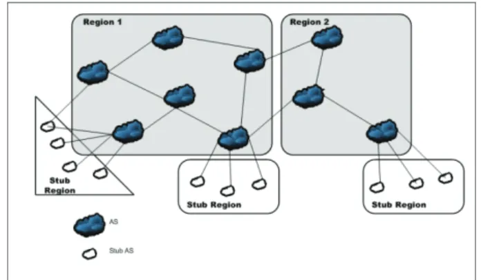
In our architecture we divide the Internet and group the autonomous systems (AS) into regions (Figure 1). The reason for using regions is the scalability of the new link-state routing protocol [40]. We model the Internet as a network I(N,L) consisting of a finite set of nodes N and a finite set of links L. Every node n
∈
N in this network is an AS. A region Ri = (V,E) is a connected graph that is asubset of network I (Ri
⊂
I), and the union of the regions isthe Internet (I = R1
∪
R2∪
...∪
Rn).Fig. 1: The Internet divided into regions
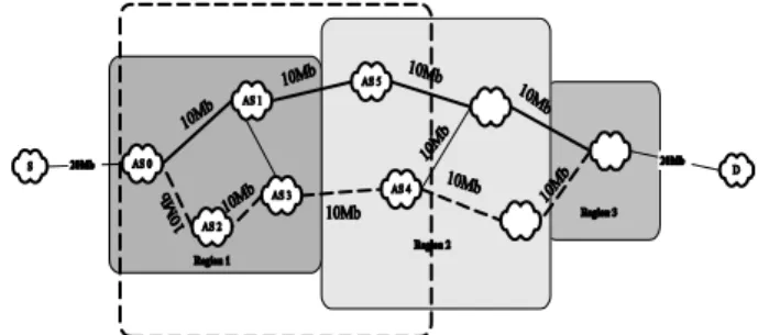
In the region-based architecture regions do not constitute a hierarchy. Inside a region, AS do not constitute a hierarchy either. All ASs reside at the same level inside a region. Figure 2 gives a small representative internetwork. In this figure every node represents an AS. Figure 3 shows a region configuration in that network. When composing groups we consider the types of AS. In a regular region there can only be transit and/or transit-only AS. Stub-AS are collected in a special region called stub-region.
Fig. 2: A sample Network
Every AS inside a region has a routing agent that is responsible for inter-domain routing and dissemination of inter-domain routing information to intra-domain routers.
Fig. 3: Regions of the sample network in Figure 2.
We assume that every domain in the Internet is a MPLS/Diffserv domain and every Diffserv domain has a Bandwidth Broker. Bandwidth Brokers communicate with each other using the SIBBS-TE protocol. Every domain also has a region-based routing agent for inter-domain QoS routing, which we will refer to as Inter-Domain Routing Agent (IDRA) hereafter. An IDRA communicates with other IDRAs of other domains and also communicates with the BB of its own domain. Figure 4 shows the inner structure of a domain in our architecture. As it can be seen from the figure, we achieve inter-domain traffic engineering through interactions of BB, IDRA inside a domain, and interactions of IDRA with each other and interactions of BB with each other via SIBBS-TE.
Fig. 4: Details of a Domain
Inter-Domain QoS Routing: The inter-domain QoS
routing protocol is one of the essential parts of our architecture. The inter-domain QoS routing protocol enables any domain in the Internet to calculate a source-specified AS-level QoS path to any destination. This calculated path is from the edge of a source domain to the edge of a destination domain. A path calculated by the inter-domain QoS routing protocol consists of a series of AS. The inter-domain QoS path does not give any details on the intra-domain paths or the border routers on any of the AS on the path.
Our inter-domain QoS routing protocol enables the use of underutilized resources when it is necessary, which improves the overall throughput on the outgoing links of a domain. This satisfies an important goal of traffic engineering, which is to efficiently utilize the resources of a network. Our QoS routing protocol also provides sufficient tools to balance the loads on the outgoing and incoming
links of a domain. Since we designed the QoS routing protocol on a link-state paradigm, the load status of every inter-domain links of a domain is advertised through QoS parameters of the links. A domain can make the forwarding decision based on the load status of the outgoing links, which is the basic idea behind load balancing. Our protocol is based on link-state, and unlike other link-state-based routing architectures [41], [42], [43], our architecture is non-hierarchical. We will briefly describe the mechanics of the routing architecture and more detailed information can be found in [40].
An AS inside a region exchanges link states with other AS inside the same region. If we keep the size of the region small, we can achieve scalability. At this level, every AS on the Internet has enough routing information to route packets to every other AS that belongs to the same region and for the routing purposes regions are disconnected. An AS does not know how to route a packet to another AS that resides in another region.
Fig. 5: Link state area of regions of network in Figure 2.
Next step is to provide a mechanism for inter-region interconnection. In order to achieve this, we expand the boundaries of link-state exchange to include the ASs that are neighbor of an AS that reside on another region. Figure 5 shows the link state exchange boundaries of the regions in our sample network. Since these edge ASs have routing information of its own region, if an AS inside R1 reaches one of these ASs, packets can be routed through R2. R2 link state boundaries include neighbor ASs in neighbor regions. Since regions constitute a connected graph, there is always a path from any AS to another AS in the Internet.
After collecting link states, every AS inside a region computes a path to every other AS that is in the link state distribution boundary. This means every AS will have a path to every other AS inside the region and also will have a path to every neighboring region. When a region wants to reach another AS in another region, that AS first computes a regional path, which shows which regions to pass to reach the destination. After computing the regional path, AS computes a path to the next region that is on the regional path. Origin AS sends a Path Request Message (PReqM) to the AS that resides on the border of neighbor region. That AS gets the PReqM, extracts the regional path and calculates a path to the next region in the regional path. This process is repeated until request arrives to the destination AS. Destination AS responds with a Path Response Message (PRespM) which includes the whole path from source to the destination. Source AS receives the PRespM, and routes the flows on this path.
In our architecture, a tunnel needs to be established before traffic starts flowing. This requires an admission control mechanism, an inter-domain signaling protocol, and an inter-domain tunnel establishment mechanism. Bandwidth Brokers, SIBBS-TE, and inter-domain LSP setup mechanism satisfies these requirements, respectively. Figure 6 shows the functionalities of each component in our architecture in a sequential manner.
When a source wants to send QoS traffic to a destination, the source sends a Resource Allocation
Request (RAR) to the Bandwidth Broker of its own domain. Any Bandwidth Broker on the Internet has to determine the next Bandwidth.
Fig. 6: Traffic Engineering in terms of functionalities of building blocks
Broker to forward the request to reach a destination. Without an inter-domain QoS routing protocol, Bandwidth Brokers rely on the BGP routes, determine the next Bandwidth Broker based on this information, and RAR is forwarded hop-by-hop until it reaches to the destination domains' Bandwidth Broker. In our architecture, upon receiving a request, the source Bandwidth Broker communicates with the IDRA of its domain and requests an explicit QoS path to the destination. The IDRA calculates an explicit QoS path, and feeds that information to the Bandwidth Broker. The Bandwidth Broker embeds this explicit QoS path into a SIBBS RAR message and forwards the RAR message to the next Bandwidth Broker on the QoS path. This process is repeated until the RAR message reaches to the destination domains' BB. The destination domains' BB prepares an RAA message and sends that message back on the reverse explicit QoS path. Bandwidth Brokers establish inter-domain and intra-domain tunnels when they receive the RAA message.
As it can be seen from the process, this architecture has two mechanisms to ensure that the QoS parameters can be satisfied. At first inter-domain QoS routing protocol calculates a QoS path to the destination. Since our inter-domain QoS routing protocol depends on the link-state approach, link-state information at the source has a chance to be outdated. During the path setup phase with the Bandwidth Brokers, we verify that the path chosen by the inter-domain QoS routing protocol indeed satisfies the QoS parameters and if the link-states changed dramatically, which invalidates the path after the path was calculated, Bandwidth Brokers on the calculated path recognize these changes and path setup will not be completed.
Having an inter-domain QoS routing protocol and Bandwidth Brokers in the architecture gives us the ability to calculate an explicit QoS path from the source and establish the inter-domain tunnels as well as intra-domain tunnels to the destination.
In our traffic engineering architecture, established inter-domain tunnels are long-lived. A tunnel to a destination can accommodate hundreds of flows that are destined to the same destination, and have the same QoS characteristics. This property of our architecture increases the scalability of the routing architecture. Once a path is established to a destination, that path will be used as long as the capacity is available, and that source does not need to calculate another path to the same destination again because of the changing link states. Establishing long-lived inter-domain tunnels eliminates the need for highly dynamic traffic control. A domain can establish multiple tunnels to a destination on different paths and balance the load on these tunnels by multiplexing flows in one of these tunnels.
BB • Autht'flllCat,on . ı\uthorız.ıtıon . Jntr.ı-Dornaın Resuurce ı:heck IDRA lııtcr•Doınaın QoS Path
D
lııtcrior BB .R~ourı:e ı:heı:k .lntra·Doıııaın ı.sr .lntı>r-Doııı.ıın Qo) p;ıttır~ıut"Sl E.xtcriur DD .Explıcıt P.ıth ::,etup (S188)-TF.) .lııter-Domaııı LSPBandwidth Brokers and Traffic Engineering Extended SIBBS Protocol- (SIBBS-TE): Bandwidth
Brokers are proposed in the IETF Diffserv framework [44]. Bandwidth Brokers are centralized agents that are responsible for control and management of a domain's resources. Bandwidth Brokers perform admission control, intra-domain and inter-domain resource provisioning, QoS state maintenance etc. Bandwidth Brokers also communicate with neighboring Bandwidth Brokers for inter-domain resource provisioning [45].
Bandwidth Brokers use Simple Inter-domain Bandwidth Broker Signaling (SIBBS) Protocol [46], which is developed by Internet2 QBone Signaling Design Team, for inter-BB communication [47]. SIBBS protocol uses two basic message types: Resource Allocation Request (RAR) and Resource Allocation Answer (RAA). RAR messages carry traffic specific information. The Bandwidth Broker in a domain can receive RAR from three different sources. One is the host in the domain that BB controls, and the other is the peer BB, and the last is a third-party agent acting on behalf of a host or application. The BB responds with an RAA to the request. For security reasons every BB authenticates the messages it receives from other BB and signs the messages it sends to other BB.
SIBBS protocol is designed to work in a sequential manner. A reservation request starts from the source domains' BB and traverses all the BB that control other domains on the path until the request reaches to the destination. Upon receiving an RAR message, a BB analyzes the message to extract QoS characteristics of the request. After extracting the QoS characteristics, the BB checks intra-domain resources of its domain to see whether there are enough resources to support the requested QoS. If there are enough resources, the BB forwards the request to the next BB. Next BB broker is determined by the BGP. Although SIBBS is the only protocol that is close to being a standard communication protocol between BB, there are several issues that need to be resolved with the SIBBS specification.
As can be seen from the reservation process, SIBBS messages are propagated to other BB using an inter-domain routing table. Selection of the next hop BB solely depends on the BGP protocol, which does not have any information regarding the quality of the inter-domain links. Even if there is an inter-domain QoS routing protocol in place, it is not possible for SIBBS to use the path specified by the QoS routing protocol because of the lack of an explicit path setup capability, which is also important for inter-domain traffic engineering applications.
Another problem with the SIBBS protocol and the processing of RAR messages lies in the distribution of the QoS parameters using RAR messages. SIBBS works perfectly for EF services, because the EF service is defined to be a practically zero loss, zero delay service. When a BB receives an RAR message requesting an EF service, it needs to verify that it can support that service for the request. If the request traverses N domains, and each individual domain satisfies the requirements, then the end-to-end QoS would also be satisfied for the EF service.
If the request is for a service that requires certain end-to-end delay bound, then SIBBS cannot provide reliable reservations for this kind of service. Let us assume from source domain to destination domain, a flow has to traverse m domains including the source and the destination. Let us say that flow's delay requirement is:
(1) ,
and let us assume that each domain has different delay characteristics and satisfies the following:
(2) , , 0,1, … ,
This condition suggests that when one of these domains receives the RAR, the delay condition specified in the RAR will be satisfied by that individual domain and the RAR will be forwarded to the next domain without a problem. One point the protocol does not take into account is that the QoS parameters specified in the RAR message is an end-to-end requirement, rather than a domain-level requirement. If we go back to the examples, when the RAR reaches the destination domain, the total delay that flow will actually see will be:
(3) ∑
where can be greater than D. This causes the BB to accept the flow without regard to the end-to-end treatment flow will receive. In order to prevent this, there needs to be modification in the processing of RAR messages by BB. In the following part, we will provide solutions to the problems we mentioned in this section.
Explicit Path Setup: Explicit path setup capability is
one of the most important features of a QoS signaling protocol for end-to-end QoS support as well as inter-domain traffic engineering purposes. We are proposing the inclusion Explicit_Path object to the RAR message of the SIBBS protocol. This object is used in a sequential manner to indicate the explicit route the RAR message needs to take.
When a BB receives an RAR message, one of the first things that BB checks is the first Explicit_Path object in the RAR message. The first Explicit_Path should include the IP address of the BB receiving the RAR message. If the first Explicit_Path does not include the IP address of that BB, the BB sends back to the sending BB an RAA message with an error code indicating that receiving BB is not the intended recipient of the RAR message. If the first Explicit_Path includes the IP address of the receiving BB, the BB continues with the regular RAR processing procedures. If all the steps have a positive outcome, the BB modifies the RAR. This modification should include deleting the first Explicit_Path object from the RAR message. This results in the second Explicit_Path object in the RAR message becoming the first in RAR and it also points to the next hop BB to which the RAR should be sent. If there is no other Explicit_Path object left in the RAR message after removing the first one, and the destination of the RAR message is a directly connected end system, BB simply removes the first Explicit_Path and forwards the RAR without an Explicit_Path object to the end system. If the destination is another domain, BB also removes the Explicit_Path object from the RAR message and forwards the RAR message to the next domain that is determined by the inter-domain routing table.
Inter-Domain Label Exchange: Another extension we
are adding to SIBBS is the inter-domain label exchange for inter-domain label switched path (LSP) setup. Addition of inter-domain label exchange mechanism is twofold. One is extending RAR message with label_request object, and the second one is extending RAA message with label object.
A label request object is used with RAR message. A BB sends an RAR message with a label request object to another BB to establish an inter-domain LSP. A label request object includes the type of the transport protocol to be used because some labels are assigned to specific protocol types [48]. Upon the receipt of an RAR, if the label request object exists in the RAR message, a BB determines the ingress router to be used for the LSP and requests a label from the ingress router. This label is stored in the BB
to be later used in RAA messages. If a resource allocation procedure results in a positive outcome and a BB receives a positive RAA, the BB allocates the intra-domain resources, modifies the RAA, which includes embedding a label object into the RAA message, and sends back the RAA message to the previous BB. When a BB receives an RAA with a label object, the BB first checks whether a label was requested for this reservation. If the label was not requested, the BB discards the label object and continues with the standard RAA processing procedures. If a label was requested, BB extracts the label from the RAA message, pushes that label to the associated egress router, and allocates intra-domain resources before modifying and sending RAA to the downstream BB. When all BB on the path from source to destination completes this signaling procedure and inter-domain LSP will be established.
End-to-end Generic QoS Support: As we mentioned
earlier, SIBBS can not be used to guarantee services other than EF. In order to support other QoS services we are modifying the processing of SIBBS messages.
SIBBS uses globally well-known services (GWKS) to communicate with other BB for the QoS constraints of a flow. This information is transmitted using a service parameterization object (SPO). When a BB receives an RAR message, the BB should update the SPO object of the RAR message. The nature of the update is determined by the type of the QoS metric embedded into the SPO. Our basic assumption is that every BB has knowledge of its own Per Domain Behavior (PDB), and the behavior that requesting flow will receive from its own domain. With this assumption in place, every BB can update the SPO to ensure that the flow will receive the requested end-to-end QoS. Let us assume the metric included in the RAR is . This is the end-to-end upper imit for the metric. Let us also assume that the flow will see from that domain. Let us define the residual metric to be
(4)
If 0, and that BB is not the last BB on the path to the destination, the BB replaces with when sending the RAR to the next domain. If 0, and that BB is not the last BB on the path to the destination, end-to-end QoS support cannot be guaranteed for the flow with the requested metrics and the BB sends back an RAA with an error code. If the metric is multiplicative, the BB repeats the same process. The only difference in this case is the calculation of . Let us assume that the multiplicative metric is the probability of a packet not being lost. In this case, If , the BB replaces with where
(5) ⁄
and sends the RAR with an updated SPO to the next domain. If , the end-to-end loss condition cannot be satisfied and the BB returns an RAA with an error code.
Evaluation Results
We simulated our architecture using ns2 [49] simulator. We implemented the inter-domain QoS routing on ns2. For the resource management and the path establishment simulations, we did not include SIBBS-TE or the inter-domain LSP setup mechanism in this simulation. Instead we used native ns2 functionalities to achieve the path setup and the resource management.
We ran our simulations on a simple topology shown in Figure 7. In this topology there are 9 Autonomous systems, 1 destination, and a source. The topology is divided into 3 core regions as shown in the Figure 7. All the links in the topology modelled to have 10Mb of available bandwidth
except for the links connecting the destination domain, and the source domain. These links have 20Mb of available bandwidth. We assume that the intra-domain capacity is always greater than the inter-domain capacity and if the inter-domain capacity is available, the intra-domain capacity is also available. Also the intra-domain resource allocation is assumed to be handled by Bandwidth Brokers. Intra-domain mechanisms are not simulated and not analyzed in this study.
Fig. 7: Network topology used for the simulation
For any flow from a source to a destination, all the 10Mb links are bottleneck links. We chose this topology to see how our architecture performs if all the links are bottleneck except for the source and the destination links. Reservation requests are sent from source to AS0. Reservation request arrivals are modelled as a Poisson Process with 0.1 seconds of interarrival time. Reservation requests are generated for 10 seconds. When a request is accepted, resources are allocated, and after 2 seconds resources are released, and bandwidth is registered as an available bandwidth again. On these simulations, only the available bandwidth is considered as a QoS parameter.
We ran two sets of tests on two different models. The first model involves hop-by-hop routing without any QoS information. Reservation requests are handled by Bandwidth Brokers and a Bandwidth Broker forwards the request to the next Bandwidth Broker on the shortest path according to the hop-by-hop routing protocol. This path is shown with the heavy lines in Figure 7. Since QoS information is not considered during the path selection process, inter-domain paths are static on a short timescale and if the resources are not available requests are rejected without looking for an alternate path. The second model employs a region-based inter-domain QoS routing protocol with Bandwidth Brokers. In this model reservation requests are also handled by Bandwidth Brokers. The difference between this model and the first model is that, in this case the source BB gets the explicit path that satisfies the requested QoS to the destination from the IDRA. After an explicit path is received, BB forwards the reservation request to the next BB on the explicit path. This model first uses the shortest available path to the destination, which is represented by the heavy lines in Figure 7; when the first path is exhausted an alternate available path is used, which is represented by dashed lines in Figure 7.
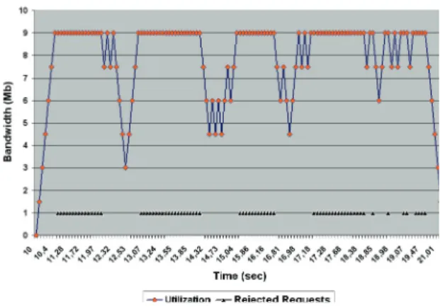
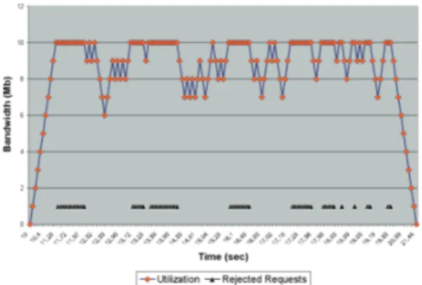
In our first set, the source requests 1Mb reservations to the destination. We tested this configuration on each of the models we explained above. We compared the utilization of the destination link with the rejected reservation rate. Figure 8 shows the results for the model without traffic engineering and Figure 9 shows the results for the model with traffic engineering. When the traffic engineering is used the destination link is utilized 86,5% on average, and 14,7% of the reservation requests are rejected. With traffic engineering, the destination link capacity is the upper limit for the maximum number of requests that can be accommodated. Reservation requests are rejected when
0-~
AS4 IOAıı, I ---~IJOMh----0
1----o~/
-
·
"'I"' ,_ _ _ _ } 1
there is less than 1Mb available bandwidth at the destination. When the traffic engineering is not employed, destination link is utilized 46% on average, and 53% of the reservation requests are rejected. In this case, minimum capacity link on the shortest path is the bottleneck. Although there is available bandwidth at the destination, reservation requests are rejected when the available capacity on the shortest path is less than the requested bandwidth. These results show our architectures' ability to divert the traffic from the congested links. When traffic engineering is employed, there is a favorite path to the destination; in this case it is also the shortest path. Reservation requests are forwarded on this favorite path as much as possible, which means when there is available bandwidth that can accommodate the requested reservation, favorite path is used. When the favorite path is exhausted, an alternate path to the destination is used.
Figure 8: Utilization and rejected requests for 1Mb reservation with no TE process.
Figure 9: Utilization and rejected requests for 1Mb reservation with TE in process.
Figure 10: Utilization and rejected requests for 1.5Mb reservation with no TE process.
Figure 11: Utilization and rejected requests for 1Mb reservation with no TE process.
In our second set, we used the same parameters as the first case, except that in this case sources make request for 1.5Mb. Resources are allocated if available and resources are released after 2 seconds from the allocation time.
Figure 10 shows the simulation results when traffic engineering is not employed and Figure 11 shows the simulation results when traffic engineering is employed. When the traffic engineering is used, the destination link is utilized 83.2% on average and 45% of the reservation requests are rejected. Reservation requests are rejected when the available capacity on the destination link is 2Mb.
Since every path to the destination has 10Mb of capacity,every path can accommodate 6 flows at one time. When both paths are exhausted, there is still 1Mb capacity left on each path. This is the reason that we have 2Mb of available capacity at the destination and the requests are rejected. In this case, bottleneck is the minimum capacity link on the alternate paths. When the traffic engineering is not employed, the destination link is utilized 41% on average, and 70% of the reservation requests are rejected. In this case bottleneck is the minimum bandwidth link on the shortest path to the destination. Although there is available bandwidth on the alternate path, when the shortest path is exhausted, reservation requests are rejected. This reduces the utilization and increases the rejection ratio.
After receiving and analyzing the results for this topology, we decided to run the same experiments on a different topology to make sure that we did not create a topology to make the approach work which would not work in any other case. We used BRITE [50] topology generator to generate a random topology with 100 Autonomous Systems. We divided this topology into 5 region. We selected two random nodes on two different regions and ran the first set of experiments on this topology first without traffic engineering and then with traffic engineering. On the first nodes we selected we got the same results as the previous simulation. Results are shown in Fig. 12, 13.
Analysis results from 100 node simulation also show another aspect of our architecture, which is load balancing. We analyzed selected paths for every accepted request. When capacity is available, flows are forwarded on the following path: 0 50 23 93 3 , where each number shows the AS-ID and subscript shows the region that AS belongs. When the capacity is fully allocated on this path, the rest of the traffic is forwarded on alternate paths and load is partially balanced on these paths. Partial load balancing is the feature that comes with the region-based QoS routing architecture. The alternate paths are:
0 87 97 93 81 32
54 3 and 0 87 97
93 19 98 54 3 . As it can be seen from
:ô !.15+-- -+--- - - - -~ >-+- +-+-- -~~ - +--+- ---l .ı:: ;; ~ ıi; 10 +---+- - - --+---< m Time (sec)
-+-Utilization - - Rejected Requests 1
1
2
-,---:ô •+--+- --++u>-- -__.,~ >H,._- ..+--+.--<>--<'--• H~ ~ .ı:: ~ 6+-- - -- -- - - -+----<i
m Time (sec)1 -+-Utilization - - Rejected Requests 1
.c !.12+--+-- ---+- - - -.__ _ _ _ _ _ _ _ _ _ _.____, .ı:: ~ 10 +-+-- - - ~f----7 .ğ j 8
"'\,::;'P'._ •. :r.._ .. 'f .._,,,\'l,.P ""''\.,'::-\.,f .., .. ;f·.,_.,.P ... -?._,,,tı!.._,,,:-? · .._ro\ro? .._rot ..,,.,.'::-.. ..,,.,.P ..,,.,.'f ..,,.,.ır ... ~:ı;,,"'._~,""...•i .._.;t-f'-::-\ ... 'Y Time (sec)
1 -+-Utilization - - Rejected Requests 1
10
\~I
1MI
il
IW\I
u
t (U l Ulil
V \AA. lll 1-
---
7
Time(sec)the paths, subpaths 81 32 and 19 98 are used exchangeably and load is balanced on region1. Both alternate paths are used in turn and when the shortest path is congested, is used for 20 times and
is used for 19 times. These results show that load balancing can be achieved on a per region basis and the same length different regional subpaths can be used to reach the same destination.
Figure 12: Utilization and rejected requests for 1 Mb reservation requests between AS0 and AS3 with no TE in process on 100 AS network .
Figure 13: Utilization and rejected requests for 1 Mb reservation requests between AS0 and AS3 with TE in process on 100 AS network.
Figure 14: Utilization and rejected requests for 1 Mb reservation requests between AS0 and AS1 with TE in process on 100 AS network.
One cannot always engineer the links to reach a certain destination. If there is no alternate path and a domain has to use a single path to a destination, traffic engineering practices fail. We selected another AS pair in 100 AS topology and ran 1Mb simulation with traffic engineering capability to see whether we can achieve the same results
as the previous one. For this particular node pair, only one path is found to reach the destination and traffic engineering did not result in any utilization gain. Result of this simulation is shown in Figure 14. As it can be seen from the graph, routing failed to find an alternate path to the destination to forward the traffic when the shortest path is congested. Even though when we consider the whole topology for path computation, there can be multiple paths to the destination that satisfies the requested QoS, region-based routing fails to find an alternate path. This is one of the tradeoffs of our architecture, which is between scalability and the path finding ability. Increasing the number of entities in link-state routing reduces the scalability which is especially true in large networks such as Internet. Another reason for not being able to find an alternate path is using static regional paths to destinations. In case of dynamic regional path calculation, a domain has the ability to calculate an alternate regional path and in turn an alternate AS level path to a destination when the shortest regional path and the shortest AS level path becomes congested.
Results of the simulation are encouraging for the usefulness of the developed traffic engineering architecture. When traffic engineering tools are employed in the simulation, total throughput is increased and the rejection ratio is decreased. In our architecture, when there is an available alternate path with enough capacity to accommodate the request, that available capacity is identified and used. In the Internet, currently only implicit traffic engineering techniques are used because of the unavailability of an inter-domain QoS routing protocol and an explicit path setup capable inter-domain signaling protocol. Our simulation results show that, our proposed architecture has the right tools for inter-domain traffic engineering.
Conclusion
In this paper we introduced an inter-domain traffic engineering architecture that is designed to work on a Bandwidth Broker supported Diffserv Internet. Our architecture consists of an inter-domain QoS routing protocol, Bandwidth Brokers, an explicit-path setup capability added Simple Inter-domain Bandwidth Broker Signaling protocol (SIBBS-TE), and inter-domain tunnel setup mechanism. We presented individual components of the traffic engineering architecture and explained how these individual pieces work together to make inter-domain traffic engineering possible. We evaluated the performance of our architecture with simulations. Our simulation results show that use of introduced inter-domain traffic engineering architecture increases the total number of QoS flows in the network, and increases the total throughput by effectively using the alternate available capacity on the network. If there is no alternate available capacity on the network, our architecture cannot improve the throughput.
In this paper we evaluated the performance of our architecture to show an alternate way of engineering the traffic and using the capacity more effectively on the inter-domain level. In our future study, we will examine the effects of different policies on the performance of our architecture and develop traffic engineering schemes to make this architecture work as effectively as possible on the Internet.
REFERENCES
[1] D. O. Awduche, A. Chiu, A. Elwalid, I. Widjaja, and X. Xiao.Overview and Principles of Internet Traffic Engineering.
RFC 3272, May 2002.
[2] Peerapon Siripongwutikorn, Sujata Banerjee, and David Tipper.Traffic Engineering in the Internet: A Survey of Load BalancedRouting,http://www2.sis.pitt.edu/peerapon/papers/te.p df. ~ 'r +- -~ ~- - -~~ ~ -- ~ H~- - - - ~~+7 ~ .c ~ 6+-- - -~ >--- - - - -- 7 ~
•
..
Time (sec)1-+-Utilization --Rejected Requests 1
~ ~15+---0-- - - ----«»-- ----<>----<>- -~ - - -~>---<>---< .c ;; ~ i 10+---<>-- - - -----<>---<
..
(O CD N "'-.,-, -O"l " ' .., ..,. - .,., ---- -- --Time (sec)1-+-Utilization ; -Rejected Requests 1
Time (sec)
PRZEGLĄD ELEKTROTECHNICZNY (Electrical Review), ISSN 0033-2097, R. 85 NR 10/2009 145 [3] Anoop Ghanwani, Bilel Jamoussi, Don Fedyk, Peter
Ashwood-Smith, Li Li, and Nancy Feldman. Traffic Engineering Standards in IP Networks Using MPLS. IEEE Communications
Magazine,December 1999.
[4] Ibrahim T. Okumus, Junseok Hwang, Steve J. Chapin, and Haci A. Mantar. Inter-Domain Traffic Engineering on a Bandwidth Broker Supported Diffserv Internet. In Proc. of the Applied
Telecommunication Symposium (ATS ’03),Orlando, Fl, 2003.
[5] Ibrahim T Okumus. Inter-Domain Traffic Engineering on a Bandwidth Broker Supported Diffserv Internet. Ph.D.
Dissertation, Syracuse University, August 2003.
[6] R. M. Mortier. Internet Traffic Engineering. Ph.D. Dissertation, University of Cambridge, October 2001.
[7] TEQUILA, Traffic Engineering for Quality of Service in the Internet, at Large Scale, http://www.ist-tequila.org/.
[8] TEQUILA Project Deliverables, D1.1: Functional Architecture Definition and Top Level Design, pg. 138, http://www.isttequila.org/.
[9] M. Boucadair. Qos-enhanced border gateway protocol.
Internet-Draft, Jul 2005.
[10] X.Masip E.Monteiro S.S´rnchez M.Curado J.Domingo M.Yannuzzi, A.Fonte. A proposal for inter-domain qos routing based on distributed overlay entities and qbgp. Proceedings
WoQSR’04, LNCS 3266, Oct 2004.
[11] A. Beben. Eq-bgp: an efficient inter-domain qos routing protocol. 20th International Conf. on Advanced Information
Networking and Applications, 2006. AINA 2006., 2, Apr 2006.
[12] MESCAL Project. http://www.mescal.org. [13] EUQoS Project. http://www.euqos.eu.
[14] J. Hwang, J. Altmann, H. Oliver, and A. Suarez. Enabling Dynamic Market-Managed QoS Interconnection in the Next Generation Internet by a Modified BGP Mechanism. The IEEE
International Conference on Communications 2002, New York, New York, USA, April 2002.
[15] B. Abarbanel and S. Venkatachalam. BGP-4 Support for Traffic Engineering. Internet Draft, work in progress, September 2000. [16] G. Cristallo and C. Jacquenet. An Approach to Inter-domain
Traffic Engineering. Proceedings of XVIII World
Telecommunications Congress (WTC2002), Paris, 2002.
[17] G. Huston. Commentary on Inter-Domain Routing in the Internet, RFC 3221. December 2001.
[18] Tracie Monk. Inter-domain Traffic Engineering: Applications in Complex Networks. Ixia, National Fiber Optic Engineers
Conference 2002, Dallas, TX, September 2002.
[19] Tracie Monk. Inter-domain Traffic Engineering: Principles and Case Examples. The Internet Society’s 12th Annual INET
Conference Inet2002, Washington D.C., June 2002.
[20] I.T. Okumus, J. Hwang, H.A. Mantar, and S.J. Chapin Inter- Domain LSP Setup Using Bandwidth Management Points. Proc. IEEE Global Communications Conference, Globecomm2001, November 2001.
[21] D. Makrakis V. Groza T. Saad, T. Yang. Inter-Domain Adaptive traffic Engineering For IP Differentiated Services MPLS-BasedNetworks. Canadian Conference on Electrical and
Computer Engineering IEEE CCECE 2002, May 2002.
[22] O. Bonaventure C. Pelsser. Extending RSVP-TE to Support Inter-AS LSPs. 2003Workshop on High Performance Switching
and Routing (HPSR 2003), June 2003.
[23] JP. Vasseur A. Farrel, A. Ayyangar. Inter-Domain MPLS and GMPLS Traffic Engineering - Resource Reservation Protocol- Traffic Engineering (RSVP-TE) Extensions. RFC5151, February 2008.
[24] Hema T. Kaur and Shivkumar Kalyanaraman. A Connectionless Approach to Intra- and Inter-Domain Traffic Engineering. 2nd New York Metro Area Networking Workshop,
New York,September 2002.
[25] Bruno Quoitin, Cristel Pelsser, Louis Swinnen, Qlivier Bonaventure, and Steve Uhlig. Interdomain Traffic Engineering with BGP. IEEE Comm. Magazine, 41(5):122–128, May 2003. [26] Bruno Quotin, Cristel Pelsser, Olivier Bonaventure, and Steve
Uhlig. A performance evaluation of BGP-based traffic engineering. International Journal of Network Management, 15(3):177– 191, May 2005.
[27] S. Uhlig, V. Magnin, O. Bonaventure, C. Rapier, and L. Deri. Implications of the Topological Properties of Internet Traffic on Traffic Engineering. In Proc. of the 19 ACM Symposium on
Applied Computing, Special Track on Computer Networks,
March 2004.
[28] S. Uhlig. A Multiple-objectives Evolutionary Perspective to Interdomain Traffic Engineering. International Journal of
Computational Intelligence and Applications (IJCIA), special Issue on Nature-Inspired Approaches to Networks and Telecommunications, 5(2):1–16, 2005.
[29] Nick Feamster, Jay Borkenhagen, and Jennifer Rexford. Guidelines for inter-domain traffic engineering. ACM
SIGCOMM Computer Communications Review, October 2003.
[30] A. Kock, S. Michaelis, J. Seger, and I. Miloucheva. Interdomain traffic engineering using advanced visual data mining technology. In International IEEE Conference on Next
Generation Teletraffic and Wired/Wireless Advanced Networking (NEW2AN’04), February 2004.
[31] R. Mahajan, D. Wetherall, and T. Anderson. Towards Coordinated Interdomain Traffic Engineering . In Third
Workshop onHot Topics in Networks HotNets-III, Nov. 2004.
[32] Kannan Varadhan, Ramesh Govindan, and Deborah Estrin. Persistent Route Oscillations In Inter-Domain Routing.
Computer Networks (Amsterdam, Netherlands: 1999), 32(1):1–
16, 2000.
[33] D. Obradovic. Real-time Model and Convergence Time of BGP. Infocom 2002, The 21st Annual Joint Conference of the
IEEE Computer and Communications Societies, June 2002.
[34] T.G. Griffin and G. Wilfong. An Analysis of BGP Convergence Properties. ACM SIGCOMM’99 Applications, Technologies,
Architectures, and Protocols for Computer Communication,
August 1999.
[35] G. Cristallo and C. Jacquenet. Providing Quality of Service Indication by the BGP-4 Protocol: the QOS-NLRI attribute.
Internet Draft, draft-jacquenet-qos-nlri-05.txt, June 2003.
[36] Francois Le Faucheur et al. MPLS Support of Differentiated Services. RFC 3270, May 2002.
[37] F. Le Faucheur et al. Requirements for support of Diff-Servaware MPLS Traffic Engineering. RFC 3564, July 2003. [38] D. Awduche et al. Requirements for Traffic Engineering Over
MPLS. RFC 2702, September 1999.
[39] J. Boyle et. al. Applicability Statement for Traffic Engineering with MPLS. RFC3346, August 2002.
[40] Ibrahim T. Okumus, Haci A. Mantar, Junseok Hwang, and Steve J. Chapin. Inter-domain qos routing on diffserv networks: a region-based approach. Computer Communications, 28(2):174–188, 2005.
[41] Yakov Rekhter. Inter-Domain Routing Protocol (IDRP).
Internetworking: Research and Experience, 4, 1993.
[42] M. Streenstrup. An Architecture for Inter-Domain Policy Routing. RFC 1478, June 1993.
[43] C. Alaettinoglu and A. U. Shankar. The Viewserver Hierarchy for Interdomain Routing: Protocols and Evaluation. IEEE
Journal on Selected Areas in Communications, (13(8):1396–
1410), October 1995.
[44] K. Nichols, V. Jacobson, and L. Zhang. A Two-bit Differentiated Services Architecture for the Internet, RFC 2638. July 1999.
[45] H.A. Mantar, Junseok Hwang, I.T. Okumus, and S.J. Chapin. A scalable model for interbandwidth broker resource reservation and provisioning. IEEE Journal on Selected Areas in
Communications, 22(10):2019– 2034, December 2004.
[46] QBone Signalling Design Team, http://qbone.internet2.edu/bb/index.shtml.
[47] QBone Bandwidth Broker Architecture, http://qbone.internet2.edu/bb/bboutline2.html.
[48] E. Rosen et al. MPLS Label Stack Encoding. RFC3032, January 2001.
[49] The Network Simulator - ns-2, http://www.isi.edu/nsnam/ns/. [50] Boston University Representative Internet Topology Generator
(BRITE), http://www.cs.bu.edu/brite/.
Authors: Asst.Prof.Dr. Ibrahim Taner Okumus, Mugla University,
Technical Education Faculty, 48000 Kotekli, Muğla, Turkey, E-mail: [email protected]; Asst.Prof.Dr. Haci A. Mantar, Gebze Instıtute of Technology, Computer Engineering Dept., 41400 Çayırova Gebze/KOCAELİ, E-mail: [email protected]; Prof. Junseok Hwang, Seoul National University, E-mail: [email protected]; Assoc. Prof. Dr. Stephen Chapin, L.C. Smith College of Engineering and Computer Science, 13244 Syracuse, NY, USA, E-mail: [email protected]