ISSN impresa 0717-3644
ISSN online 0718-221X DOI: 10.4067/s0718-221x2021000100419
STRUCTURAL ANALYSES OF WOODEN CHAIRS BY FINITE
ELEMENT METHOD (FEM) AND ASSESSMENT OF THE CYCLIC
LOADING PERFORMANCE IN COMPARISON WITH ALLOWABLE
DESIGN LOADS
Erkan Ceylan1 https://orcid.org/0000-0002-0497-7789 Ersan Güray2 https://orcid.org/0000-0001-5349-6511 Ali Kasal3,♠ https://orcid.org/0000-0002-4632-0072 ABSTRACTTests were carried out to investigate the cyclic loading performance of chairs constructed of Scotch pine (Pinus sylvestris) and Oriental beech (Fagus orientalis). Totally, 30 real size chairs were constructed and assembled with polyvinyl acetate adhesive. Chairs were tested under 3 cyclic loading directions; namely, front to back, back to front, and backrest according to American Library Association (ALA) specifications, and obtained loading performances of chairs were crosschecked with allowable design load levels. Additionally, specimens were analyzed as structures by using the finite element method in order to obtain axial, shear, and bending stresses acting on each member under loadings and compare these values with design stresses. As a result, it was concluded that finite element method analyses achieve reasonable estimates for strength performances and failure behaviors of chairs. Depending on allowable design loads by American Library Association; chairs constructed of beech could meet the medium service for front to back and back to front loading, while heavy service for backrest loading. In the case of pine chairs; they could meet the medium service for front to back and back to front loading, while light service for backrest loading.
Keywords: Acceptable design loads, chair strength, cyclic loading, finite element analysis, furniture
engi-neering design, structural analysis, wooden.
INTRODUCTION
The design of the new furniture should satisfy three main criteria such that it should have an aesthetic looking, functional, durable and also feasible. The first one requires esthetic design; that is, the artistic +development of the furniture structure, the design of the second is necessary for the use/functionality of the furniture such that the furniture structure is planned to have the capability of its intended functionality, and the last can be obtained by an engineering design; that is, the furniture can safely resist the loads imposed upon it in its service life and manufactured with minimum cost. Until recently, the engineering design received little attention. However, it is becoming increasingly important because of various reasons such as; consumer demands for more reliable furniture, government pressures for warranties of furniture, increasing needs for
material economics, among others. (Eckelman 2003).
The design of furniture almost rests on traditional experiences in handcraft manufacturing. As far as known, no manufacturer or designer applies static analyses to determine the internal forces inside the wooden members of a furniture body. However, some researchers have shown interest in this field (Gustafsson 1997). The section size and geometries of members that integrate the furniture frames should be designed rationally and they should carry the acceptable loads probably imposed upon them in service. In the methodology of furniture engineering; once forces and moments these acting to the ends of each member have been analyzed, the internal stresses in these members can be calculated and by comparing their magnitudes with the allowable design stresses for the material used, it can be seen whether or not each of the members has been safely designed. This process provides a methodical way of designing a piece of furniture to meet any specified service condition.
In many types of furniture, members may be deliberately oversized so that no attempt is made to determine the optimum or most efficient size for each member. The principal task of the designer in such cases is to verify that each member can safely carry the forces imposed upon it without exceeding the allowable stress design values. When members are used solely for structural purposes such as in upholstered furniture, however, they often may be engineered exactly to meet specified strength requirements. The objective here is to produce an optimum overall design in which just enough material is used to produce a piece of furniture that is capable of carrying specified design loads with a given factor of safety. Such designs, being the most economical, provide savings for both the manufacturer and consumer together (Eckelman 2003).
Today, technology has rapidly developed. Just like in other industrial areas, technological developments have been effective in the production of furniture from design to manufacturing. With the help of recent technological improvements and innovations, furniture could be produced at high-speed and robustness; furthermore, the constructional details are able to be analyzed in details. The precise analysis of furniture frames is a complicated process in terms of computation, since there exist a large number of internal forces to be determined for an effective solution. It is very important to use technological facilities in the strength design of furniture (Kasal et al. 2006). It is well possible to utilize structural analyses and solid modelling software to accomplish the design of furniture. In addition, the finite element method (FEM) provides a furniture designer with enormous possibilities for analysis and design.
In this context, furniture members, joints, and the whole system could be modelled parametrically via FEM. It is required to make simplifications while modelling the structure, for instance, the geometry can be taken as rough as possible and the connections are modelled by semi-rigid springs. If the numerical results do not well satisfy the experimental output, then some detailing modifications are done on the model to provide a better approximation. Strength calculations of the designed elements and connection points require realistic modeling and loading of the system. Then, required constraints are provided to optimize the member sizes by interpretation of these internal forces (Kasal et al. 2006).
Recent studies show that the FEM has become widespread in the structural analysis of furniture systems. In (Tankut et al. 2014), a bibliographical review of the FEM, used in the analysis of wooden furniture products is listed. In another work, it is shown that the design of a chair can be very different if some simple calculations are performed. In this study, additionally, it was underlined that there had been a need for the wood analysis not in “building size” but “furniture size” (Gustafsson 1995). Some analytical models were developed for the furniture frame analysis using FEM by Kasal and Pullela (1995). The load-deformation curves were gathered by experiments and the stiffness is determined by incorporating the resulting curves with the loading. In the end, it was stated that FEM models had been helpful to simulate the furniture under loading (Kasal and Pullela 1995). A computer program was developed for the strength analysis of wooden frames. In this study, the side frame of a chair was analyzed and it was shown that accurate and practical strength analysis of the wooden members could be performed by this program (Smardzewski 1998). He developed a mathematical model for bent-mortise joints, in his other work, and tried to discover influencing factors on the strength of glued-tenon-joints. Analyses were performed with a computer assisted program and according to results, the flexural strength of the glued-mortise-tenon-joints was depending on mostly the shear strength of the adhesive and the compression strength of the wood material (Smardzewski 2016). In the study carried by Kasalet al. (2016a), mortise and tenon joints in various sizes were analyzed by FEM and some strength properties like the bending capacity, stiffness of the joint were reported. Joints became stronger and stiffer by increasing the tenon sizes. The maximum stress was concentrated on the edge and corners of the glued surface and it was declared that the strength properties of the joints have a shape-adhesive nature (Kasal et al. 2016b). The research was
capacity of the flexible chairs was tested both experimentally and numerically. In the case, of a weight until to 110 kg chairs met the requirements of actual standards but failed for heavy loadings (Langova et al. 2019). In the literature, there are many studies related to the ultimate and allowable strength of solid wood and wooden materials. And, safety factors were recommended for calculating the allowable design loads (Eckelman 2003, Forest Products Laboratory - USDA 2010). There are some studies related to the allowable design loads for whole furniture systems. Among these studies, the most important references are GSA (FNAE 80-214) and ALA. In these references, allowable cyclic design loads for upholstered sofas and chairs were given by classifying the light (domestic), medium, and heavy duty service (Eckelman 1982, Eckelman 1995a, Eckelman 1995b, Eckelman 1999, Eckelman and Erdil 2001). The strengths of beech chairs were investigated under cyclic and static loading. The cyclic front to back load performance of chairs was compared with the acceptable design loads such that, it was recommended that the cyclic strength could be assumed to be 56 % of the strength of static loading case (Kuskun et al. 2018). Kiliç et al. (2018) investigated the effects of tenon size, in the case of the front to back loading of Scotch pine chairs, and the strength of chairs wich were evaluated according to the acceptable design loads. Chairs with joints connected by 40 mm in width and 50 mm in length tenons were capable of meeting light service which corresponds to the domestic usage. However, a minimum of 50 mm x50 mm size was required for the width and length of each tenon, respectively, to meet the requirement of the medium service (Kiliç et al. 2018). In the other study, the relationship between the loading capacity of beech chairs and strength of side frame joints was investigated where the chair was subjected to the front to back single push. In addition to this, a methodology was developed for predicting the strength of chairs from the strength of joints (Kasal et al. 2016a).
As seen in the literature, generally, the performances of chairs were evaluated in the case of the front to back loading. There are very limited studies that evaluated the cyclic strength of the wooden chairs in all loading directions. The purpose of this study was to measure the cyclic loading performance of wooden chair frames by comparing the allowable design load levels in three loading directions given in ALA specifications. Furthermore, chair frames were structurally analyzed by using FEM and collected data were compared to the actual strength test results. As a result, it was intended to promise information about the cyclic loading performance of wooden chairs and to show the usage of structural analyses via FEM in furniture engineering design.
MATERIALS AND METHODS Materials properties
Chair members were constructed from beech (Fagus orientalis L.) and pine (Pinus sylvestris L.) woods. They are procured from local commercial suppliers and are used quite often in the furniture industry. The average density values of these species are 0,63 g/cm3 and 0,48 g/cm3, respectively. Other physical and
mechanical properties are taken as shown in ASTM D143-94 (2000) and ASTM D4442-92 (2003) standards. Whole chair frames were constructed by utilizing grooved beech dowels. They were 10 mm in diameter and 35 mm in length. 65% solid contained PVAc (polyvinyl acetate) glue is used to assemble the chair members. This type of glue is highly preferred since it is easily spread and dried, cold applied, odorless and fire resistant. Necessary properties of it are provided by the company (Polisan, Turkey) as density of 1,1 g/cm3, viscosity of
0,16 - 0,2Pa/s, ph = 5,00, ash rate of 3%.
Construction of the chairs and individual joint specimens
A total of 30 (2 wood species, 3 loading direction, 5 replication) chairs were prepared in 1/1 scale. 15 chairs were constructed of beech, and the remaining 15 were constructed of pine. The general configuration of the chairs is shown in Figure 1.
Figure 1: (a) Dimensions in mm (b) the real picture of the chairs.
First of all, surfaces of wooden beams were smoothed at the planing machine and pieces with a thickness of 21 mm were prepared. Then, they were cut to have a 60 mm width for all members except for stretchers. The stretcher was 21 mm thick and 30 mm wide. Assembling starts with the construction of side frames. Mortise and tenon joint techniques were utilized for constructing the side frames of the chair. The length and the width of tenons were set to 40 mm at side rails, they were 30 mm for the stretcher since it was only 30 mm in width. Corresponding mortise holes were drilled on back and front legs with a 7 mm thickness (1/3 of the member thickness). Mortises were drilled and tenon joints were cut with appropriate laboratory machines. A tight fit was obtained where the average mortise–tenon clearance was 0,076 mm ± 0,025 mm. In the assembly, walls of the mortises and tenons were first adequately coated with adhesive. The adhesive was spread over approximately with 150 gr/cm2 ± 10 gr/cm2. The tenons were then inserted into the mortises, and the assembly
was squeezed by bar clamps. Then a complete chair was built by these preassembled pieces utilizing dowel joints. The depth of the embedment of dowels in the edge and the face were 20 mm, 15 mm, respectively. The distance between the two dowels was chosen to be 30 mm. The dowels and corresponding holes at the top and back rails and the lower front and back rails were coated with adhesive. Bar clamps were again used to squeeze the side frames to force the dowels for a tight fit.
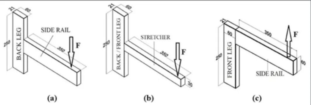
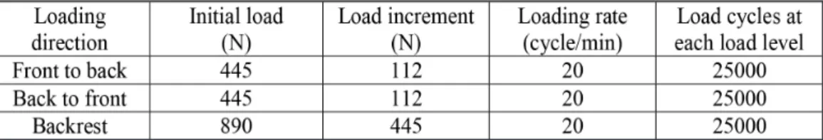
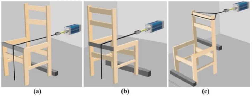
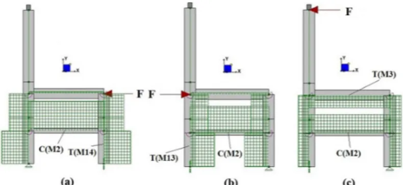
Not only whole chairs were constructed but also representative T-type and L-type specimens were prepared for obtaining the moment rotation characteristics (stiffness coefficients) of each joint in order to introduce them as semi-rigid connections in the structural analyses of chairs. Each joint type was tested 20 times since there had been 2 wood species and tests were replicated 10 times. Therefore, 20 identical T-type joints for the connections between the “back leg to side rail” and 20 identical T-type joints for the connections between the “back/front leg to stretchers” were prepared. Separately, 20 identical L-type specimens for modelling the connection between the “front leg to side rails” were arranged. T-type and L-type joint specimens and load directions are shown in Figure 2a, Figure 2b, and Figure 2c.
As a precaution for a unique moisture content (MC), before examining, all chairs and joint specimens were kept in an environmentally controlled conditioning room to cure at least one month for reaching an average 12 % moisture content.
Cyclic performance testing of chairs and moment-rotation characteristics of joints
The “cyclic stepped increasing loading” is a recommended method to satisfy the requirements of the performance test system. To do this, the furniture is subjected to a specified initial load at a prescribed cyclic rate for a specified number of cycles. When cycles are accomplished, the subjected load is raised incrementally. Cycling loading is repeated after each increment. The procedure is repeated until the desired load level has been reached, or failure occurs on the furniture frame, or horizontal deflection exceeds 50 mm on the side rail and back leg connection (Eckelman 1988, Eckelman 1999).
In the scope of the study, a total of 30 chair frames were constructed and tested. Chairs were tested regarding the principles of the American Library Association (ALA) specification by applying the cyclic front to back, back to front, and backrest loads to which the chairs were likely to be exposed in service (Eckelman 1999). The cyclic loading tests were performed on the furniture performance testing equipment (Mates 2011, Ankara, Turkey) at the mechanical testing laboratory in the Wood Science and Industrial Engineering Department of Mugla Sitki Kocman University. The cyclic loading test procedure was that 1) a chair was subjected to a given load for 25000 cycles at a rate of 20 cycles per minute, 2) when 25000 cycles were completed at this load level, the load was increased a specified amount and testing continued for next 25000 cycles, and 3) this procedure was repeated until the tested chair suffers disabling damage or the desired acceptance level were reached. When performing the cyclic stepped increasing loading procedure, “initial load,” “load increment,” “loading rate,” and “load cycles at each load level” practiced in the study are given in Table 1. 25000 cycles at each load level took almost 21 hours (about 1 day) in cyclic loading for chairs. In the tests, the ultimate failure loads (in Newton) and completed total cycles were recorded.
Table 1: Loading program of cyclic loading tests for chair frames (Eckelman 1999).
In the front to back and back to front loading tests; horizontal loads in specified directions were applied from 420 mm away from the supports. In these tests, reaction brackets were fixed behind each of the back legs for front to back loading while they were placed in front of each of the front legs for back to front loading in order to prevent the chair from slipping. Steel chains then passed over the seat and attached to the air cylinders that were used to apply the horizontal loads to the chair. The other end of the steel chains dropping over the front edge of the seat for front to back loading, while the back edge of the seat for back to front loading, was attached to the floor vertically. Chains provided the reaction forces preventing the chair from overturning. (Figure 3a and Figure 3b).
In the case of the backrest loading test, a reaction bracket was placed just behind the back legs with the same height of side rails, and another bracket was placed in front of the front legs. Here, just similar to cases of back to front or front to back loadings, reaction brackets prevented the chair from tipping over backward when front to back loads applied to the backrest. A short steel chain was tied around the backrest and fixed to the air cylinder (Figure 3c).
Figure 3: Tests; (a) front to back loading, (b) back to front loading, (c) backrest loading.
The allowable cyclic loading performance levels for light (domestic), medium and heavy usages are listed in Table 2 as given in the ALA specifications (Eckelman 1999). Tests were performed and the resulting performance values are to be declared and compared with these specified design loads in the next step.
Table 2: Allowable design loads according to the loading direction (Eckelman 1999).
The moment rotation characteristics of joints in the side frame of the chair were determined to treat them as semi-rigid connections in the structural analyses. The moment-rotation characteristics of the joint were determined by the relationship between the distortion angle between neighboring orthogonal members and the applied moment. It could be considered as the rotational, linear behaving, stiffness coefficient and evaluated by Equation 1:
M
K
ϕ
=
(1)where K is the stiffness coefficient (Nm/rad), M is the moment (Nm) and ø designates the distortion angle at the joint (rad).
T-type and L-type joint specimens were examined under bending loads to simulate the condition in which they are exposed to these loads as in the side frame of a full chair (Figure 2). Static loading tests were performed on the 50 kN capacity universal-testing machine (Mares, İstanbul, Turkey) with the 6 mm/min loading rate. The rail member of each specimen at a point 300 mm from the front edge of the leg was subjected to a concentrated load, such that, the moment arm was 300 mm according to the literature (Kasal et al. 2016a, Kiliç et al. 2018).
Dial gage was clamped to the edge of joint rails and the measurements were recorded at regular intervals as specimens were loaded.
Structural analysis of chairs
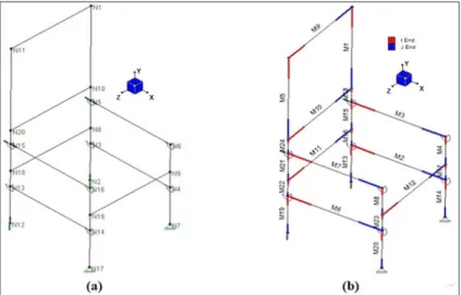
A chair structure is a frame structure where the members are assumed to be linear beams. Here, in this work, every member is a prismatic member having a width, length, and depth. The model was created with joints and the interconnected beam elements between them (Figure 4). Each joint was labelled from N1 to N20 and members were numerated from M1 to M24. This FEM modelling was performed on RISA-3D (2000) and all internal forces were determined.
Figure 4: Joints/nodes (a) and members (b) of the modelled chair.
Rotational linear springs were modelled at the T-type and L-type side frame connections to treat them as semi-rigid connections. Since the software was able to assign semi-rigid connections by simply assuming springs at these joints, simply, predefined K (rad/mm), stiffness coefficients are entered into the interface of the program (Table 3). The stiffness coefficients were determined based on the bending tests of representative T-type and L-type joints, as was previously explained.
Table 3: Stiffness coefficients, K, obtained for each joint type according to wood species.
Next, some required physical and mechanical properties (Table 4) of beech and pine obtained from the tests were entered into the software to calculate the axial, shear forces and, moments at the end of members. Poisson’s ratio (µ) was taken as 0,3 for both species (Kasal et al. 2006, Kasal et al. 2016b, Kiliç et al. 2018).
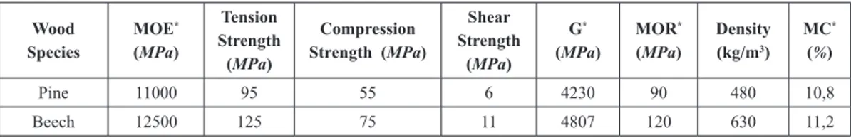
Table 4: Physical and mechanical properties of pine and beech woods used in the study. Wood Species MOE * (MPa) Tension Strength (MPa) Compression Strength (MPa) Shear Strength (MPa) G* (MPa) MOR * (MPa) Density (kg/m3) MC* (%) Pine 11000 95 55 6 4230 90 480 10,8 Beech 12500 125 75 11 4807 120 630 11,2
*MOE: modulus of elasticity; G: shear modulus; MOR: modulus of rupture, MC: moisture content.
Then, sectional properties, i.e., the cross-sectional area, the moment of inertia values about local (Y) and (Z) axes, form factor and, torsional constant values were calculated and implemented into the workspace (Table 5).
Table 5: Sectional properties of the chair members.
After all physical and mechanical definitions for the problem, the supports should have been assigned. For the front to back loading; front legs connection to the floor were treated with roller supports, whereas the back legs were supposed to have pin connections with the floor. In other words, it was considered that back legs were constrained to translations in (X), (Y), and (Z) directions, while they were free to rotate in any direction; but the front legs, were constrained to the translation only in (Y) direction. For the back to front loading; unlike the front to back loading, back legs of the chair were supported as roller, whereas the front legs were supported as pinned. And finally, when it was loaded at the backrest; the back legs of the chair were supported as a roller, whereas the front legs were supported as pinned, in addition, the back leg to side rail joints were supported as the roller. Other than the support joints, all internal joints (nodes) were defined with six degrees of freedom, in other words, all internal joints can carry the axial forces, shear forces, and bending moments in any direction. The numerical model was subjected to static analysis by loading properly. The ultimate loads that were obtained from the actual tests were cyclic performance, but it was performed the FEM analyses with static loads. Therefore, it was considered the relation between the cyclic and static strength. According to the literature; cyclic strength is approximately half of the static strength, so in the structural analyses, it was applied twice the loads that were obtained from the actual tests (Kasal et al. 2016a, Kuskun et al. 2018, Likos et
al. 2013). Ultimate loads were symmetrically applied at corresponding nodes that were on the two side frames
(Figure 5).
Axial, shear forces, moments, and corresponding stresses acting on each member was obtained. Furthermore, axial force, shear force, and, moment diagrams and deflected shape of the chair was also provided as the output of the software.
Figure 5: Loading and supports of the numerical model, loaded in direction of (a) front to back,
(b) back to front, and (c) backrest.
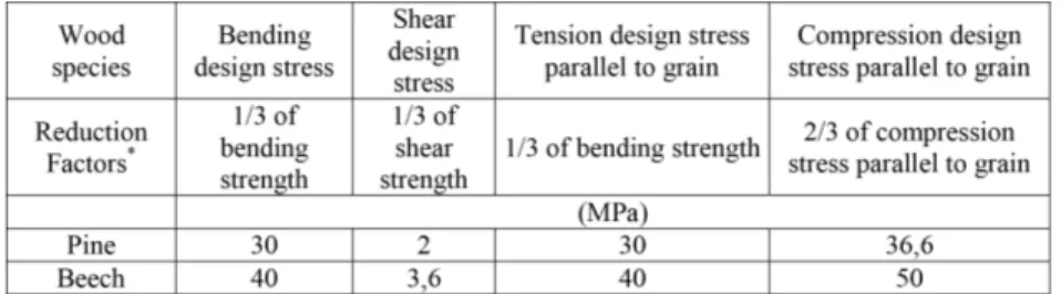
The axial forces (tension or compression), shear forces, and moments were obtained from the structural analyses for all members of the chair under each loading direction. Corresponding axial, shear and bending stresses were also available and ready to be compared with the allowable design stresses. To find the allowable design stresses, values given in Table 4 were multiplied by the appropriate reduction (safety) factors (Eckelman 2003). Table 6 also shows the allowable design stresses for the materials used in the construction of the chairs.
Table 6: Allowable design stresses for the wood materials used in the construction of chair*.
*Reduction factors are taken according to Eckelman (Eckelman 2003).
As a result; deformation characteristics observed in actual tests were tried to verify by structural analysis. In other words, the consistency of the joints where deformations occur in actual tests was checked with the results of structural analysis.
RESULTS AND DISCUSSION Structural analysis results of chairs
stresses. In the case of frames tested under backrest loading; failures occurred owing to fracture of the tenons at their point of entry into the walls of the back and front legs or fracture of the back leg member at the top of the back leg to side rail joints. The exaggerated deflected shapes of a chair under the three lading directions obtained from the FEM analyses and actual tests are given in Figure 6 and Figure 7, respectively.
Figure 6: Deflected shape of chair obtained from the structural analyses under, (a) front to back loading,
(b) back to front loading, and (c) backrest loading.
Figure 7: Observed deformation characteristics of chairs under, (a) front to back loading,
(b) back to front loading, and (c) backrest loading.
As seen in Figure 6 and Figure 7, deflected shape of the chairs obtained from the structural analyses under each loading direction have given reasonable estimates in terms of the overall deformation characteristics and possible failure points of the chairs.
In the strength analyses of the chairs, the axial forces and corresponding axial stresses under the front to back, back to front, and backrest loadings were considered initially. Axial force diagrams are given in Figure 8 with the most critical tension and compression members.
Figure 8: Axial force diagrams obtained from the structural analyses results for (a) front to back loading,
Regarding loading, the bottom part of the back leg member is exposed to a high compression due to the front to back loads while the bottom part of the front leg member is pulled up from the test set-up platform, and exposed to tensioning because of the pin supports. On the contrary, for the back to front loading; the bottom part of the front leg member is subjected to high compression while the bottom part of the back leg member is sustaining tension. In both loading directions, stretcher members are exposed to a considerable amount of compression. In the case of the backrest loading; the side rail member is exposed to a tension force while the stretcher member is exposed to a compression force.
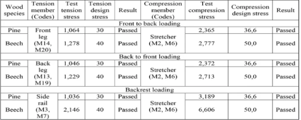
The members pointed out in Figure 8, were compared to the allowable axial design stress values determined for each wood material used. It was found that the maximum tension stresses (T) occurred in the bottom part of the front leg member (M14, M20) under the front to back loading, in the bottom part of the back leg member (M13, M19) under back to front loading, and in the side rail member (M3, M7) under the backrest loading. In the case of maximum compression stresses (C), has occurred in the stretcher member (M2, M6) for all three loading directions. These members are the most critical members for carrying the axial forces under the loadings. The comparison results for the consequential ultimate axial stresses and allowable axial design stresses were given in Table 7.
Table 7: Comparison of the maximum axial stresses values and axial design stresses (MPa).
As seen in Table 7, chairs made of both wood species were found to be strong enough to carry the axial forces safely for all loading cases. The shear forces in direction (Y) and corresponding shear stresses under the front to back, back to front, and backrest loadings were provided as the second phase. Shear force diagrams were presented in Figure 9 with the most critical shear members for all loading directions.
Figure 9: Shear force diagrams obtained from the structural analyses results for (a) front to back,
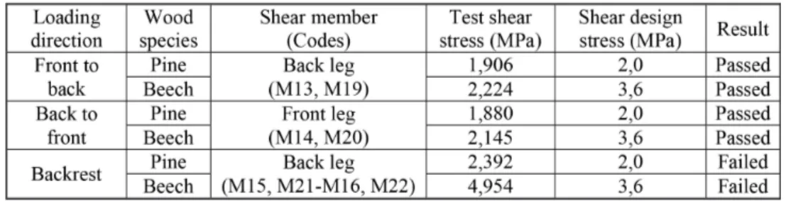
loading, maximum shear stresses occurred in the middle part (between the side rail and stretcher) of the back leg member (M15, M16 and M21, M22). These critical members’ results for shear stresses which act upon the back leg-bottom members and allowable shear design stresses were given in Table 8.
Table 8: Comparison of the maximum shear stresses and shear design stresses.
According to Table 8, it was found that, chairs, nevertheless they are made of pine or beech, had enough capability of carrying design loads in the case of both fronts to back or back to front loadings. However, the shear stresses that occurred in the middle part of the back leg under backrest loading were higher than the allowable shear design stresses for both chairs constructed of pine and beech. This result was consistent with observations in actual backrest loading tests. In the actual tests, failures occurred at these members and/or related (back leg to side rail or back leg to the stretcher) joints.
In the last phase, the moments about the (Z) axis and consequential bending stresses were obtained from the results of structural analyses. Moment diagrams about the (Z) axis obtained from the structural analysis results were presented in Figure 10 with the most critical members and their ends.
Figure 10: Moment diagrams obtained from the structural analyses results for (a) front to back,
(b) back to front, and (c) backrest loading.
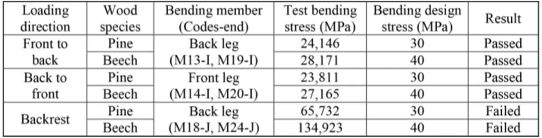
The maximum bending stresses (B) occurred in the (I) end of the bottom part of the back leg member (M13-I, M19-I) where it was joined the stretcher member (M2, M6) under the front to back loading. Therefore, the most critical point of the chair is the joint where the back leg connected to the stretcher. On the contrary, the maximum bending stresses occurred in the (I) end of the bottom part of the front leg member (M14-I, M20-I) where it was joined the stretcher member (M2, M6) under back to front loading. So, for this loading direction, the most critical point of the chair is the joint where the front leg connected to the stretcher. In the case of backrest loading, the back leg member was subjected to a considerable amount of bending stresses at the point (M18-J) where it was joined the side rail member (M3). The results are summarized in Table 9.
Table 9: Comparison of the maximum bending stresses and bending design stresses.
According to comparison results, the maximum bending stresses occurred in the back leg member where it was joined the side rail member among the three loading directions. Therefore, the most critical place of the chair is the back leg to side rail joints. Determined bending stress values that act upon these joints have gone beyond the allowable bending design stresses for both wood species.
The overall performance of the chairs has been seriously affected by the bending capacity of these joints and the section sizes of the related members. In the engineering design of a chair, if these results are taken into consideration, the strength performance of the chair can be upgraded.
Here, in this study, all possible forces and consequential stresses are investigated for both wood species. When the literature is examined, it is stated that the bending moment is the most critical internal force through them. The axial strength of even a very small sized wood member is generally much greater than needed, and shear strength is rarely of concern (Eckelman 2003). In this study, it has been understood that either beech or pine used chair members, and sectional sizes of each member of the chair had enough capacity to carry the axial (tension or compression) forces, safely, whereas the members of the back leg where it was joined the side rail or stretcher member has been imposed to over bending and shear forces. This fact is well compromised with the actual performance test results in terms of failure locations. In other words, actual test failures occurred in these joints where the structural analyses showed that the highest stresses occurred. In the backrest loading tests; firstly, softening failures occurred in the mentioned joints, and catastrophically, other joints were also untightened. In some chairs, the back leg member of the chair or tenons of the back leg to side rail joints were broken. These results helped to confirm that the FEM model of the chair was consistent with the experiment chair.
Assessment of the cyclic loading performance of chairs with allowable design loads
The mean ultimate cyclic strength performance values of tested chairs under each loading direction with their coefficients of variation are summarized in Table 10.
%, 12 %, and 51 % stronger than the chairs constructed of pine for front to back, back to front, and backrest loading, respectively. Test results indicated that the ultimate cyclic loading performance of the chairs was significantly affected by the wood species. Differences in ultimate cyclic loading performance of the chairs could be explained by differences in physical and mechanical properties, especially joint strengths, shear and bending strength of the wood material used constructing the chairs.
According to Table 10, it has been seen that the front to back and back to front loading performance values of the chairs were close to each other for both wood species. The backrest loading performance values of the pine chairs were also close to the other loading directions. However, backrest loading performance values of the beech chairs were significantly higher than the front to back and back to front loading performances.
The cyclic loading performances of chairs under the front to back, back to front, and backrest loadings were compared to the allowable light, medium, and heavy design load levels that were given in the ALA specifications (Eckelman 1999). The allowable light design load levels represent the domestic use in practice. The assessment results of chairs are given in Table 11 for each loading direction.
Table 11: Comparison of loading performance values of chairs with allowable design loads.
According to results, chairs constructed of pine could meet the allowable medium service load requirements for front to back and back to front loading directions, whereas they could only resist allowable light service (domestic usage) load requirements for backrest loading direction. In the case of chairs constructed of beech; they could satisfy the allowable medium service load requirements for front to back and back to front loading directions, and could meet the heavy service load requirement for backrest loading. These results were graphically shown in Figure 11.
Figure 11: Assessment of performances of the chairs under the cyclic (a) front to back, (b) back to front, and
(c) backrest loading.
CONCLUSIONS
This study was aimed to acquire quantitative information related to the cyclic front to back, back to front, and backrest loading performances of chairs, constructed of Scots pine and Oriental beech. In addition to that, it is intended to compare the cyclic loading performance of chairs with the allowable design loads that were
specified in ALA specifications. Furthermore, chairs were structurally analyzed by using the finite element method (FEM).
Generally, it was concluded that the overall design and construction of the pine chairs evaluated in this study would be satisfactory for light service, while beech chairs would be satisfactory for medium service. Thus, it can be said that the chairs constructed of pine and beech are extremely suitable for domestic usage. In fact, it is possible to reduce the cross-sectional dimensions of these chairs in order to obtain economic and ergonomic benefits if they are used for domestic usage. As expected, chairs constructed of beech yielded higher strength than those of pine. Although beech yielded higher strength, pine could be commonly utilized in the furniture frames in an engineering design approach because of its economic advantages.
Chairs constructed of both species were given close cyclic loading performance under the front to back and back to front directions. The backrest loading performance of pine chairs was also close to other loading directions. However, the backrest loading performance of beech chairs was significantly higher than the front to back and back to front loading directions.
At the end of the structural analysis results, the most critical loading was backrest loading. Under this loading, members and especially back leg to the side rail and back leg to stretcher joints of the chair were subjected to considerable amounts of shear and bending stresses, and general failures occurred at these joints. Eventually, it can be concluded that the overall strength of the chairs by considering initially the bending stress capacity of the members, secondly, section sizes and, finally the strength of the joints. Results indicated that structural analysis by Finite Element Analysis (FEA) methods provide reasonable estimates of the overall strength of these structures consistent with actual performance testing results. In addition, the results also showed that performance testing is an important part of furniture engineering methodology and provides quantitative feedback to designers. Performance testing enables exploration and investigation of unforeseeable failures and ensures fruitful conception to actual usage and failure conditions.
In conclusion, this study confirmed that product engineering methodology, integrating structural analyses with performance testing is applicable to the design of chairs. A similar methodology can be followed for designs of other types of furniture.
ACKNOWLEDGMENTS
This paper is a part of MSc. thesis of the first author. The study was supported by Scientific and Technological Research Council of Turkey (TUBITAK) with the project number; 216O013, and Muğla Sıtkı Koçman University Scientific Research Project Office with the project number; 17/112. Preliminary data of this paper were verbally presented at the V. International Furniture Congress which was held in Eskişehir, Turkey. Then, data sets were expanded before converting into a scientific manuscript.
REFERENCES
ASTM. 2000. Standard Test Methods for Small Clear Specimens of Timber. ASTM D143-94. 2000.
ASTM International: West Conshohocken, PA, USA. https://doi.org/10.1520/D0143-94
ASTM. 2003. Standard Test Methods for Direct Moisture Content Measurement of Wood and
Wood-Base Materials. ASTM 4442-92. 2003. ASTM International: West Conshohocken, PA, USA.
https://doi.org/10.1520/D4442-92R03
Eckelman, C.A. 1982. The Use of Performance Tests and Quality Assurance Programs in the Selection of
Library Chairs. Library Technology Reports: Chicago, USA.
Eckelman, C.A. 1999. Performance testing of side chairs. Eur J Wood Prod 57: 227-234.
https://doi.org/10.1007/s001070050047
Eckelman, C.A. 2003. Text book of Product Engineering and Strength Design of Furniture. Purdue
University: West Lafayette, Indiana, USA, 65-67. https://www.agriculture.purdue.edu/fnr/faculty/eckelman/ pdf/pdm0scan.pdf
Eckelman, C.A.; Erdil, Y.Z. 2001. General services administration (GSA) upholstered furniture test
method. FNAE 80–214: A description of the method with drawings. West Lafayette. Indiana, USA.
Forest Products Laboratory. USDA. 2010. Wood Handbook: Wood as an Engineering Material. General
Technical Report. USDA. Forest Products Laboratory: USA. https://doi.org/10.2737/FPL-GTR-113
Gustafsson, S.I. 1995. Furniture design by use of the finite element method. Eur J Wood Prod 3(4):
257-260. https://doi.org/10.1007/s001070050084
Gustafsson, S.I. 1997. Optimizing ash wood chairs. Wood Sci Technol 31(4): 291-301.
https://doi.org/10.1007/BF00702616
Kasal, B.; Pullela, S.V. 1995. Development of analytical models for furniture, Raleigh. Technical Note,
North Carolina State University, Furniture Manufacturing and Management Center: Raleigh, NC.27695,80.
Kasal, A.; Birgul, R.; Erdil, Y.Z. 2006. Determination of the strength performance of chair frames
constructed of solid wood and wood composites. For Prod J 56(7–8): 55-60. https://forestprodjournals.org/ loi/fpro
Kasal, A.; Kuşkun, T.; Haviarova, E.; Erdil, Y.Z. 2016a. Static Front to Back Loading Capacity of
Wood Chairs and Relationship between Chair Strength and Individual Joint Strength. BioResources 11(4): 9359-9372. https://doi.org/10.15376/biores.11.4.9359-9372
Kasal, A.; Smardzewski, J.; Kuskun, T.; Erdil, Y.Z. 2016b. Numerical analyses of various sizes of
mortise and tenon furniture joints. BioResources 11(3): 6836-6853. https://doi.org/10.15376/ biores.11.3.6836-6853
Kiliç, H.; Kasal, A.; Kuşkun, T.; Acar, M.; Erdil, Y.Z. 2018. Effect of tenon size on static front to back
loading performance of wooden chairs in comparison with acceptable design loads. BioResources 13(1): 256-271. https://doi.org/10.15376/biores.13.1.256-271
Kuskun, T.; Kasal, A.; Haviarova, E.; Kilic, H.; Uysal, M.; Erdil, Y.Z. 2018. Relationship between
static and cyclic front to back load capacity of wooden chairs, and evaluation of the strength values according to acceptable design values. Wood Fiber Sci 50(4):402-410. https://doi.org/10.22382/wfs-2018-052
Langova, N.; Reh, R.; Igaz, R.; Kristak, L.; Joscak, P. 2019. Construction of Wood-Based Lamella for
Increased Load on Seating Furniture. Forests 10 (525). https://doi.org/10.3390/f10060525
Likos, E.; Haviarova, E.; Eckelman, C.A.; Erdil, Y.Z.; Ozcifci, A. 2013. Technical note: Static versus
cyclic load capacity of side chairs constructed with mortise and tenon joints. Wood Fiber Sci 45(2): 223-227. https://wfs.swst.org/index.php/wfs/article/view/41
Rapid Interactive Structural Analysis. RISA. 2000. RISA Technologies Software. RISA Tech, Inc.:
Lake Forest, California. United States. https://risa.com/products/risa-3d
Smardzewski, J. 1998. Numerical analysis of furniture constructions. Wood Sci Technol 32(4): 273-286.
https://doi.org/10.1007/BF00702895
Smardzewski, J. 2016. Numerical analysis of furniture constructions. Wood Sci Technol 32(4): 273-286.
https://doi.org/10.1007/BF00702895
Tankut, N.; Tankut, A.N.; Zor, M. 2014. Finite Element Analysis of Wood Materials. Drvna industrija