DESIGN AND DEVELOPMENT OF AN
SSVEP BASED LOW COST, WEARABLE,
AND WIRELESS BCI SYSTEM
a thesis submitted to
the graduate school of engineering and science
of bilkent university
in partial fulfillment of the requirements for
the degree of
master of science
in
electrical and electronics engineering
By
Abdul Waheed
August 2019
Design and Development of an SSVEP based Low cost, Wearable, and Wireless BCI System
By Abdul Waheed August 2019
We certify that we have read this thesis and that in our opinion it is fully adequate, in scope and in quality, as a thesis for the degree of Master of Science.
Yusuf Ziya Ider(Advisor)
Beh¸cet Murat Ey¨ubo˘glu
Hacı Hulusi Kafalıg¨on¨ul
Approved for the Graduate School of Engineering and Science:
Ezhan Kara¸san
ABSTRACT
DESIGN AND DEVELOPMENT OF AN SSVEP BASED
LOW COST, WEARABLE, AND WIRELESS BCI
SYSTEM
Abdul Waheed
M.S. in Electrical and Electronics Engineering Advisor: Yusuf Ziya Ider
August 2019
It has become a challenging research topic to design and develop cheap and wear-able brain-computer interface (BCI) systems but not compromising the perfor-mance. In this thesis, the design and development of a steady state visually evoked potential (SSVEP) based BCI system has been presented which is a low cost, wearable BCI system and gives highly accurate target identifications with good information transfer rate (ITR). It is a battery powered, wireless BCI sys-tem and ensures the complete isolation to the subject. Like all the BCI syssys-tems, it is designed and implemented in five major parts: (i) stimulator which is a mi-crocontroller based circuit and provides the frequency modulated visually evoked potential (f-VEP) and code-modulated visually evoked potential (c-VEP) stimu-lations (ii) dry active electrodes which capture the electroencephalography(EEG) signals from the O1, O2, and Oz head positions (iii) high sampling rate, 4-channel EEG data acquisition hardware which acquires the EEG signals, amplify them, converts them to digital data, and transmits the data using wifi communication (iv) the data processing unit (DPU) which is a MATLAB script to process the raw EEG data and displays the results and (v) the headset which mounts all the components except DPU and is developed using 3D printing technology. The first prototype of the proposed BCI system has been developed in 331 USD and tested for both the f-VEP and c-VEP modalities on six human subjects. For f-VEP modality, it exhibits an average accuracy (live accuracy) of 92.1% and av-erage ITR (live ITR) of 69.5 bits/min on the basis of target identifications done on 1.04 s data recordings. If we extract one message character from five con-secutive target identifications, the average message accuracy goes to 98.8% and average message ITR to 17.2 bits/min. In case of c-VEP modality, it exhibits live accuracy of 70.1 % and live ITR of 23.5 bits/min while message accuracy of 90.7 % and message ITR of 12.4 bit/min.
iv
¨
OZET
DHGUP BAZLI UCUZ VE G˙IY˙ILEB˙IL˙IR B˙IR TELS˙IZ
BBA S˙ISTEM˙IN˙IN TASARIM VE GEL˙IS
¸T˙IR˙ILMES˙I
Abdul Waheed
Elektrik ve Elektronik M¨uhendisli˘gi, Y¨uksek Lisans Tez Danı¸smanı: Yusuf Ziya Ider
A˘gustos 2019
Performanstan ¨od¨un vermeden ucuz ve giyilebilir bir beyin-bilgisayar aray¨uz¨u (BBA) sisteminin tasarımı ve geli¸stirilmesi zorlayıcı bir ara¸stırma konusu olmu¸stur. Bu tezde, ucuz ve giyilebilir olan, b¨uy¨uk oranda hatasız hedef be-lirlemesi yapabilen, ve kabul edilebilir Enformasyon Transfer Hızına (ETH) sahip olan, Dura˘gan Hal G¨orsel Uyarılmı¸s Potansiyel (DHGUP) bazlı bir BBA sistem-inin tasarım ve uygulaması sunulmaktadır. Bu system bataryadan beslemeli ve telsiz oldu˘gundan ¨ozneye tam izolasyon sa˘glamaktadır. T¨um BBA sistemleri gibi 5 kısım olarak tasarlanmı¸s ve uygulanmı¸stır: (i) Frekans Mod¨ulasyonlu G¨orsel Uyarılmı¸s Potansiyel (FMGUP) ve Kod Mod¨ulasyonlu G¨orsel Uyarılmı¸s Potan-siyel (KMGUP) uyartımlarını sa˘glayan mikrokontrol¨or bazlı uyarıcı, (ii) Elek-troansefalogram (EEG) sinyallerini O1, O2, ve Oz kafa pozisyonlarından kaydet-meye yarayan kuru aktif elektrotlar, (iii) EEG sinyallerini y¨ukselten, sayısala ¸ceviren ve telsiz haberle¸smeye g¨onderen 4-kanallı y¨uksek ¨ornekleme hızlı veri toplama sistemi, (iv) Bilgisayar/laptop tarafında Matlab kullanan, ham veriyi i¸sleyen ve sonu¸cları g¨osteren Veri ˙I¸sleme ¨Unitesi (V˙I ¨U), (v) V˙I ¨U dı¸sında t¨um bile¸senleri ta¸sıyan ve 3D yazıcı teknolojisiyle ile geli¸stirilmi¸s olan kafalık. ¨Onerilen sistemin ilk prototipi 331 ABD doları altında bir komponent maliyetiyle ¨uretilmi¸s ve 6 denekde FMGUP ve KMGUP modalitelerinin her ikisi i¸cin de denenmi¸stir. FMGUP modalitesinde, 1.04 saniyelik kayıtlardan anında yapılan hedef tespit-lerinde, ortalama “canlı do˘gruluk” y¨uzde 92,1 ve ortalama “canlı ETH (Enfor-masyon Transfer Hızı)” 65.5 bit/dakika olmu¸stur. Pe¸spe¸se 5 hedef tespiti sonu-cunda bir mesaj ¸cıkarma yapıldı˘gında ortalama “mesaj do˘grulu˘gu” y¨uzde 98.8 ve ortalama “mesaj ETH” de˘geri 17.2 bit/dakika olarak ¨ol¸c¨ulm¨u¸st¨ur. KMGUP modalitesinde ise “canlı do˘gruluk” y¨uzde 70.1 ve “canlı ETH” 23.5 bit/dakika olurken, “mesaj do˘grulu˘gu” y¨uzde 90.7 ve “mesaj ETH” de˘geri 12.4 bit/dakika olmu¸stur.
vi
Acknowledgement
First of all thanks to Allah with whose mercy I am going to complete Masters degree in the challenging field of electrical engineering. At this big moment, how can I forget my parents who always keep praying for me. I always have a safety cover of their love hearted prayers due to which I feel much smoothness in the proceeding of my life. I am much thankful to my wife (Humaira) who always stand by me in every thick and thin of my life. She kept pushing me until I made my mind to do masters after a long gap of 7 years from completing my BS engineering. I also want to take the opportunity of this big moment to thank my uncle (mamu Abdul Wahid) and aunt (phupho Sharifan) for their always kind behavior and sincere prayers. I also want to thank all my family members for always giving me respect and love.
I highly acknowledge the biggest contribution of my advisor “Prof Yusuf Ziya Ider” who remained kind to me and guided me to fulfill my degree requirements. He talked to me not only on the technical topics but also on many other socio-political topics. I always enjoyed to have conversations with him. I also want to pay my best regards and bundle of thanks to Suleman memon who always helped me in technical difficulties as if they were his problems. I am also thankful to Muhammad Nabi, Toygun, Yi˘git, and ¸celik who made the working environment friendly and peaceful.
I want to thank T¨urkiye Bilimsel ve Teknolojik Ara¸stırma Kurumu (T ¨UB˙ITAK) for supporting this study through research grant 114E153.
I could not be able to start masters degree without the motivations given by my beloved boss at my office “Dr. Shahid Ali”. He encouraged me to excel in my studies and spared me from office duties for this purpose. I cannot forget the motivational lectures of Kashif Iqbal. The kindness of Inam Bhai is also a great factor to persue my degree. I would like to thank all of my office colligues and friends like Sajjad Usmani, Nisar, Yasir, Shoaib, A.Wahid, Asif, Rafaqat, Faisal, Usama, Shamoon, Sufyan, Saad and many more. My love goes to Raghib, Raziq,
viii
Zeeshan, Amjad, Arshad Shakir, Sajidullah and Mazhar.
Life becomes boring without friends. I also want to thank all my friends who help me to live far away from home country in a lively and joyous way. I have spent one of my best spans of life in Bilkent University which is memorable due to my minions group (Bareera Bhabi, Naveed, Talha, Furqan, Zakwan and Saeed Ahmed). I want to say special thanks to Zakwan and Saeed to keep me with them at all hangouts. It was an unforgettable time spent with them. I can never forget the ever smiling face of Anjum Bhai and Faiza Bhabi and their always helping nature. I also want to thank Zakaullah, uncle GM, Abdul Hakeem, Abdul Wahid and Sajid Amin to remain in contact and supportive to me during my stay at Bilkent.
I am also thankful to my brother Waqar Ahmed who took my charge of fulfilling the domestic responsibilities and took a very good care of my children in my absence. I also want to take the opportunity to thank my cousin and best friend Imran with whom I can share everything.
At this moment, I want to remember my grandmother with whom I spent best days of life (Childhood). May Allah rest her soul in peace and reward her a high place in paradise. As last words, I want to dedicate this thesis to my parents, to my wife, and to my children (Abdul Aleem, Abdul Ahad, and Manha Abdul Waheed).
Contents
1 Introduction and Background 1
1.1 Background . . . 1
1.1.1 Brain Computer Interface (BCI) . . . 1
1.1.2 Electroencephalography (EEG) . . . 4
1.1.3 EEG Based BCI Systems . . . 7
1.1.4 SSVEP Based BCI Systems . . . 11
1.1.5 Practical BCI Systems . . . 13
1.2 Objective and Scope . . . 15
1.3 Organization of the Thesis . . . 16
2 Design and Implementation of the Proposed BCI System 17 2.1 Stimulator . . . 18
2.1.1 Battery . . . 19
CONTENTS x
2.1.3 Stimulator Circuit . . . 22
2.2 Dry Active Electrodes . . . 28
2.2.1 Dry electrodes . . . 29
2.2.2 Active Circuit . . . 29
2.3 EEG Data acquisition hardware . . . 31
2.3.1 EEG Amplifier Unit . . . 32
2.3.2 Microcontroller Unit . . . 33
2.3.3 Wifi Transmitter and Receiver . . . 35
2.3.4 Power Supply Unit . . . 37
2.3.5 Integrated EEG Data Acquisition Hardware . . . 38
2.4 Data Processing Unit (DPU) . . . 41
2.4.1 Data Collection . . . 41
2.4.2 Separating the data for each channel . . . 42
2.4.3 f-VEP data processing and display of results . . . 43
2.4.4 c-VEP data processing and display of results . . . 45
2.4.5 Extracting the Final Message String . . . 47
2.4.6 Graphical User Interface (GUI) . . . 49
2.5 3D Printed Headset . . . 51
CONTENTS xi 3.1 Experimental Setup . . . 53 3.1.1 Hardware Setup . . . 54 3.1.2 Software Setup . . . 54 3.2 f-VEP Experiment . . . 56 3.3 c-VEP Experiment . . . 58 3.4 Offline Analysis . . . 58 4 Experimental Results 60 4.1 Performance Evaluation Metrics . . . 60
4.1.1 Accuracy . . . 60
4.1.2 Information Transfer Rate (ITR) . . . 61
4.2 f-VEP Experiments . . . 61
4.2.1 Data Collection . . . 61
4.2.2 Data Conversion . . . 62
4.2.3 Pre-processing . . . 63
4.2.4 f-VEP Processing . . . 64
4.2.5 Results of f-VEP Experiments . . . 67
4.3 c-VEP Experiments . . . 68
4.3.1 Pre-processing . . . 69
CONTENTS xii
4.3.3 Results of c-VEP Experiments . . . 72
5 Discussion and Conclusion 75 5.1 Discussion . . . 75 5.1.1 Cost . . . 75 5.1.2 Wearability . . . 77 5.1.3 Performance . . . 78 5.2 Conclusion . . . 80 A Data 93 B Code 94 C Bill of Materials 96
List of Figures
1.1 General Structure of a BCI system . . . 3 1.2 Electrode positions over the skull described by 10-20 international
system . . . 6 1.3 A 6 × 6 matrix of alphabets and numbers which can be used for
BCI speller application . . . 8
2.1 The Breakdown structure of the proposed BCI system . . . 17 2.2 Flow diagram showing the flow of data through the system . . . . 18 2.3 The 7.4V Lithium polymer rechargeable battery . . . 19 2.4 The representative image of the Power LEDs used in the stimulator 20 2.5 The array of three LEDs (marked as L, C, and R) mounted on the
3D printed headset . . . 21 2.6 ATMEGA328P microcontroller chip in 32-pin TQFP package . . 22 2.7 Schematic of the stimulator circuit . . . 24 2.8 Layout of the stimulator circuit using DipTrace . . . 24
LIST OF FIGURES xiv
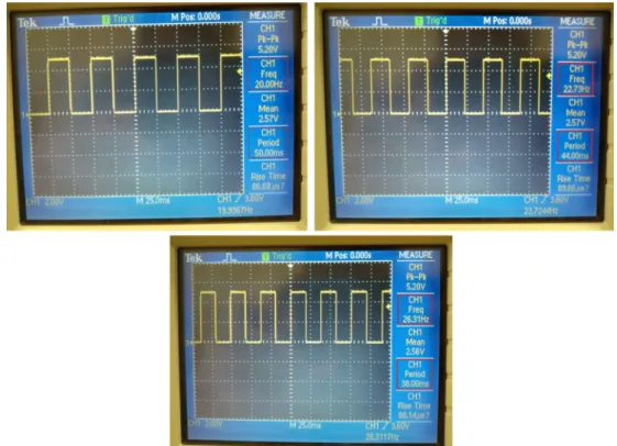
2.9 The stimulator circuit layout printed on a PCB . . . 25 2.10 The stimulator circuit implemented on a 120 mm × 21 mm PCB . 25 2.11 The oscilloscope screen shots showing LED drive signals for f-VEP
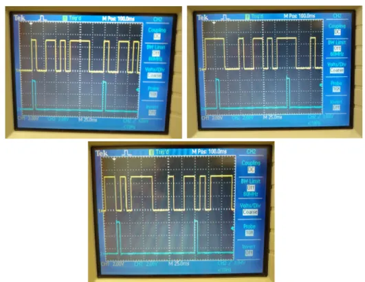
stimulation (20 Hz, 22.73 Hz, and 26.32 Hz square waves) . . . 26 2.12 The oscilloscope screen shots showing LED driving drive signals
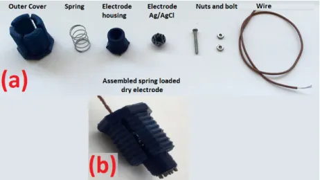
for c-VEP stimulation (three pseudo-random m-sequences) . . . . 28 2.13 A sample of dry electrode from OpenBCI (a) shows the individual
parts and (b) shows the assembled form of the spring loaded dry electrode . . . 30 2.14 Schematic of the active circuit (a unity gain amplifier implemented
using TL272 op-amp). The bottom op-amp(U1.2) is of no use in the ciruit. It is placed because the IC package has two op-amps. . 30 2.15 (a) Active circuit layout (b) active circuit PCB (top view) (c) active
circuit PCB (bottom view) (d) The complete dry active electrode having dry electrode and active circuit wrapped in thin copper sheet to provide shielding to the circuit . . . 31 2.16 The 4-channel EEG data acquisition chip (ADS1299-4) in 64-pin
TQFP package . . . 33 2.17 The timing diagram of the communication protocol used to
ex-change data with the EEG chip (ADS1299) . . . 35 2.18 Real look of the node microcontroller (node MCU) used as wifi
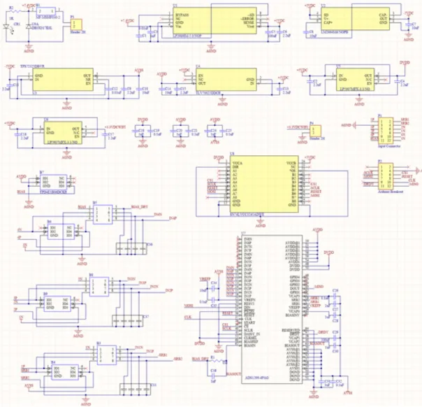
Rx module and ESP8266 wifi module used wifi Tx module in the proposed BCI system . . . 36 2.19 The schematic diagram of the 4-channel EEG data acquisition
LIST OF FIGURES xv
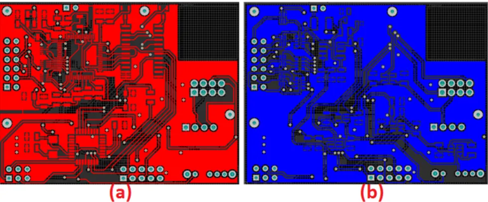
2.20 The PCB layout of the EEG data acquisition hardware (a) Top view (b) Bottom view . . . 40 2.21 EEG data acquisition hardware circuit implemented on a double
sided PCB (a) Top view (b) Bottom view . . . 40 2.22 All the steps of data processing in case of f-VEP experiments shown
as a cyclic process . . . 44 2.23 All the steps of data processing performed in the training stage of
c-VEP experiments shown as a process . . . 46 2.24 All the steps of data processing performed in test stage of c-VEP
experiments shown as a cyclic process . . . 47 2.25 Extraction of final message string from the live decisions using
synchronous method . . . 49 2.26 Extraction of final message string from the live decisions using
asynchronous method . . . 49 2.27 A sample GUI window after completing a c-VEP experiment . . . 50 2.28 (a) The small box containing the active circuit PCB (b) The three
spring load dry electrodes mounted on the headset . . . 51 2.29 The stimulator part of the 3D printed headset (encircled)
contain-ing LEDs array and the stimulator circuit PCB . . . 52 2.30 The complete 3D printed headset mounting 2 DC batteries, EEG
data acquisition hardware, dry active electrodes, and the stimulator 52
3.1 The battery connection: red wire male part should be inserted into red side of the battery connector and black wire to the black side 55
LIST OF FIGURES xvi
3.2 Initial GUI window when the “GUI.m” file is run . . . 55 3.3 GUI window after selecting the datasource (serial for online test
or file for offline analysis) . . . 56 3.4 The stimulator part of the 3D printed headset: The button to
select the stimulation modality (f-VEP or c-VEP) is encircled . . 57 3.5 A sample GUI window during an online f-VEP experiment . . . . 57 3.6 The GUI window after selecting the datasource as “File” for offline
analysis . . . 59
4.1 A sample raw data shown as comma separated byte values (0-255) 62 4.2 A sample raw EEG signal extracted from one f-VEP recording
(1.04 seconds) for channel “Oz” . . . 63 4.3 (a)The EEG signal after passing through 10-90 Hz bandpass filter
and (b) the spectrum of filtered signal . . . 64 4.4 The graphs (a),(c),& (e) show the averaged EEG responses
corre-sponding to 20Hz, 22.73Hz, and 26.32Hz respectively and (b),(d),& (f) show their respective spectra . . . 65 4.5 A sample GUI window after completing an f-VEP experiment . . 66 4.6 (a) One recording (1.05 sec) of raw EEG data for channel Oz (b)
The same data after passing through 4 − 121 Hz bandpass filter . 69 4.7 (a) One recording of EEG data for channel “Oz” after removal of
DC offset (b) The marker channel signal during the same time . . 70 4.8 The EEG response averaged over the number of trials of the code
LIST OF FIGURES xvii
4.9 (a) The target template1 (blue) and the test signal (red)(b) The target template2 (blue) and the test signal (red)(c) The target template3 (blue) and the test signal (red) (d) The correlations of the test signal with the target templates . . . 72 4.10 A sample GUI window after completion of a c-VEP experiment . 73
List of Tables
4.1 Experimental results showing the proposed BCI system perfor-mance in case of f-VEP modality. “Avg” stands for “Average”
and “std” stands for “standard deviation”. . . 68
4.2 Experimental results showing the proposed BCI system perfor-mance in case of c-VEP modality. “Avg” stands for “Average” and “std” stands for “standard deviation”. . . 74
5.1 The rough estimates of the cost of the prototype BCI system . . . 75
5.2 Comparison of cost and key features of the proposed BCI system with commercially available low cost BCI systems . . . 76
C.1 Bill of materials of the active circuit . . . 96
C.2 Bill of materials of the stimulator . . . 97
C.5 Bill of materials of the EEG data acquisition hardware . . . 99
Chapter 1
Introduction and Background
1.1
Background
1.1.1
Brain Computer Interface (BCI)
As the name suggests, the brain-computer interface(BCI) systems provide a direct link of communication between the brain and the external world (e.g. computer or any other electronics device). They do not need any physical device or typical muscular activity for delivery of information to the outside world. Normally if we want to give some command to a simple coffee making machine, the brain initiates cognitive processes and then activates particular motor activity and our hand presses the button to complete the interaction with the machine. In case of BCI systems all these intermediate activities are bypassed and the signal from brain is directly interpreted to start the device accordingly. In other words, BCI systems form a communication bridge between the brain and the outside physical world. They manage to send messages directly captured from the brain of hand-icapped people to the computer or some other device to help them to communi-cate their silent ideas or opinions using variety of BCI application like BCI speller application[1], semantic categorization[2], or silent speech communication[3].
The motivation behind the development of BCI systems is the fact that cer-tain features of the brain activity signals are linked to the specific mental states. Therefor, a BCI system measures one or more of these features and translate them to certain meaningful commands to interact with the devices/machines. The fea-tures which have been used in the previous studies include neuron’s actions poten-tials (APs) recorded from the cortex, event related potenpoten-tials (ERPs) recorded from the cortex[4] electroencephalography (EEG) features like p300 evoke po-tential, visually evoked potential (VEP), magnetoencephalography(MEG), func-tional magnetic resonance imaging(fMRI), and positron emission tomography (PET) [5]. The recordings of APs and ERPs from cortex, head surgery is re-quired which may cause medical complications while MEG, fMRI and PET are technically complex and much expensive techniques. Since EEG technique is fast, cheap and easy to implement, it is widely used in the modern research of BCI systems.
A typical BCI system involves several generic steps to establish a direct inter-active link between the brain and the external device/machine, as follows [6]:
a. Signal acquisition: Acquisition of the brain signals (includes electrodes to capture the brain signals, buffering and amplification, analog to digital (A/D) conversion and communication to the computer etc.)
b. Preprocessing: Converting raw data for further advanced steps c. Feature extraction: Extraction of desired features from the data d. Classification: Classification on the basis of the extracted features
e. Translation: Converting classified feature into computer command f. Application Interface: The interface between computer’s commands and
the real application
Figure 1.1: General Structure of a BCI system
On the basis of the technique used from data acquisition, the BCI systems can be categorized in three groups as follows:
1.1.1.1 Invasive BCI Systems
These BCI systems acquire brain signals directly from the cortex, so to implement such systems scalp surgery is required to implant the electrodes into gray matter. The main advantage of using invasive techniques is to get better signal quality and more accuracy as the signals are directly acquired from the brain without even having the scalp in between[6]. But this may lead severe medical complications as the body of the patient may not accept the implanted electrodes. The scar tissues may be formed as a reaction to the surgery, which will cause to weaken the brain signals [6][7]. The research on invasive BCI systems is mainly focused on the repairing of damaged visual system and provide some movement options to the paralyzed people.
1.1.1.2 Partially Invasive BCI Systems
In partially invasive BCI systems, the electrodes are implanted subdurally on the brain’s surface inside the skull but the system rests outside the brain (i.e., the electrodes do not penetrate to the gray matter). An example of such systems is electrocorticography (ECoG). The partially invasive BCI systems enjoy the ad-vantages of very high signal quality, lesser susceptibility to various artifacts than non-invasive techniques, high spatial resolution (< 1cm) and high temporal reso-lution (< 1ms) [6]. The disadvantage of the partially invasive techniques is again
the risk of a permanent hole in the skull which may cause medical complications [6].
1.1.1.3 Non-invasive BCI Systems
The non-invasive BCI systems installed outside the brain and the signals are acquired from over the skull. In this technique, the signal quality becomes very poor because much of the signal’s power gets damped by the scalp. Also there is dispersion and scattering of the electromagnetic waves generated by the neurons [6]. Although the quality of the signals is low in this technique, substantial majority of the research in the field of BCIs has used non-invasive EEG based BCI systems. The reason behind this is obviously its easy implementation without having risk of medical complications.
1.1.2
Electroencephalography (EEG)
EEG provides the measure of the electrical activity taking place in the brain as a result of synaptic excitations of the neurons [8]. It can be classified into five sets of signals based on their frequency ranges. These sets are named as delta (δ), theta (θ), alpha (α), beta (β) and gamma (γ) signal [8]. The band of delta(δ) signal lies below 4 Hz and it is more prominent in babies and its amplitude decreases with the age. In adults, it is detectable only in deep sleep state [8]. 4 − 7 Hz band is named as theta (θ) waves. In a normal adult in awake state, the EEG activity in the theta (θ) band is very small while it is larger in children, and adults in drowsy, sleep and meditative states [9]. Alpha(α) waves lie in 8−12 Hz range and they are found over the occipital lobe of the brain [10]. The amplitude of these waves become prominent when eyes are closed and the body is relaxed. It starts disappearing as the eyes are opened and mental activity comes into play. So the alpha waves can be associated with the mental effort [11]. Beta (β) waves lie in the range of 12−30 Hz. They are associated with motor activities taking place in the brain’s central and frontal regions. They are symmetrically distributed when
there is no motor activity but as soon as there comes some active movement, its distribution becomes unsymmetrical and amplitude is attenuated [12]. The band ranging from 30 − 100 Hz is termed as gamma (γ) waves. In a healthy human, these waves are associated to certain motor functions [13] like maximal muscle contraction [14]. Gamma waves are not commonly used in the EEG based BCI systems because they are easily affected by the artifacts like electromyography (EMG) or electrooculography (EOG) [15].
EEG signals can be captured easily from the scalp surface and there is no need to make a hole in the scalp to capture the signals. This feature of the EEG signals makes it a most popular technique among the people doing research in the field of BCI [8]. However, there is a big challenge ahead to use these signals for the purpose of building the BCI systems. The problem is that the EEG signal’s quality recorded from the scalp is very poor because the signal has to face attenuation, scattering and blurring effects [6] while crossing the skull, scalp and many other layers [8]. This means that the acquisition of reliable EEG signals from the scalp is not that easy. Moreover, the EEG signal (having amplitude of the order of µV) is very prone to be affected from the various noise sources inside and outside the brain [8]. External sources include power line which may generate 50/60 Hz background noise and internal sources cause thermal, flicker, burst and shot noises [16]. So, the EEG signal acquisition stage should contain such a good quality EEG signal acquisition system (electrodes, amplifiers, A/D converters) which not only record the signal but also prevent it from getting affected by the surrounding noises.
The EEG signal is acquired by measuring the potential difference between the desired electrode position (active position) and the reference electrode position (reference position). A third electrode position (known as ground position) con-nected directly to the electronic circuit’s common is also used for the acquisition of differential voltage signal between the active position and the reference posi-tion. So minimum of the three electrodes are required to acquire the EEG signal from some position over the head. The physical positions of the electrodes over the scalp were first described by developing the 10-20 international system [17] to acquire repeatable results from multiple recordings. The 10-20 international
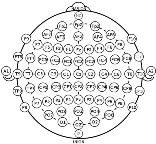
system standardizes the placement positions of the EEG electrodes on the basis of external landmarks and regular separation between the electrodes [18]. It uses two points of the head as reference to define the electrode positions. One of these two reference points is named as ”Nasion” while the other as ”Inion”. The Nasion is marked on the top of the nose at the level of the eyes while the Inion is present at the bony lump at he skull’s base. The 10-20 international system diagram is shown in Figure 1.2:
Figure 1.2: Electrode positions over the skull described by 10-20 international system
In the above figure, letter symbols are used to represent the specific regions of the brain. Letter C corresponds to the central region, P to the parietal lobe, F to the frontal lobe and O to the occipital area. The regions between these areas are represented by combination of these letters such as CP represents the region between central and parietal area.
1.1.3
EEG Based BCI Systems
EEG based BCIs are widely employed by the researchers due to minimum health risks and it is relatively convenient to conduct studies and to find volunteer hu-man subjects [19]. Since BCI systems are supposed to provide a link between the recorded brain activity and the user’s intentions, there should be some cor-relation/linkage among the user’s wills/actions and the brain activity. The EEG signals consist of a very large number of simultaneous phenomena taking place due to cognitive tasks. Out of such a large number of simultaneous responses researchers should be able to decode a few physiological phenomena so that they can be modulated with the user’s intentions. The most commonly used modali-ties in the current BCI systems are P300 evoked potentials, sensorimotor rhythms (SMR), slow cortical potentials (SCP), and visually evoked potentials (VEP) [8].
1.1.3.1 P300 Evoked Potential
The first BCI system based on P300 evoked potential was reported by Farwell and Donchin[20] in 1988. The control signal in this BCI system was a positive potential which appears after 300 ms from the occurrence of target stimulus. The P300 signal can be extracted from the EEG recordings by simply averaging it [19]. In P300 evoked potential modality, the stimulus is designed such that there are some frequent events called non-target stimuli and one is the rare event termed as target stimulus. These events may be related to the visual, auditory or somatosensory stimuli [8].
Farwell and Donchin presented to their subjects a 6 × 6 matrix containing alphabets (A-Z) and some symbols. The rows and columns of the matrix were intensified in a random way and the subjects were asked to focus on the target letter/symbol and perform some mental task (e.g., counting in mind the number of times the target letter/symbol is flashed). In this way they implemented a speller BCI using P300 evoked potential. An example of the 6 × 6 matrix which can be used as stimulator in P300 speller BCI is shown in Figure 1.3.
Figure 1.3: A 6 × 6 matrix of alphabets and numbers which can be used for BCI speller application
Since P300 signal is obtained by averaging the EEG signals, numerous trials of the experiment are required to get the p300 evoked potential signal. So, the information transmission rate (ITR) and accuracy of the P300 based systems are low [21]. Many studies are held to improve both of these parameters. Accuracy can be improved by designing a complicated classifier instead of using simple average [21][22]. The detection accuracy of P300 based BCI employing visual stimuli is also dependent on the size and color of the letters/symbols. The small sized letters/symbols give low detection accuracy [23]. The green blue chromatic flicker gives more accuracy while gray black chromatic flicker gives less accuracy [24][25]. ITR can be improved by employing modern techniques of error detection and correction in the real time [26].
1.1.3.2 Sensorymotor Rhythms (SMR)
When a person thinks or performs some movement related tasks, the changes in the amplitudes of the signals lying in alpha and beta frequency bands have been observed [27]. Many studies in this field have revealed that the movement imag-ination (known as motor imagery) may amplify or suppress the EEG amplitudes from the sensorimotor areas of the brain [27][28]. On the basis of these two ampli-tude modulation behaviors, the SMRs can be divided into two categories named
as ERD (event-related desynchronization) and ERS (event-related Synchroniza-tion) [12]. ERD corresponds to the suppression of the EEG amplitudes while ERS to its enhancement as a result of motor imagery or actual motor activity.
Apart from the changes in amplitudes of alpha and beta band’s signals, the amplitude variation is also observed in the gamma band (relatively higher fre-quencies) and very low frequency band (< 1 Hz) [28][29]. In short, SMR contains considerable amount of complementary kinematic information about the motor activity and motor imagery. This very important neurophysiological informa-tion has been decoded and made part of the many BCI controls [29]. The well known examples of such BCI systems utilizing SMRs are Graz [30], Berlin [31] and Wadsworth [32] BCIs.
1.1.3.3 Slow Cortical Potential (SCP)
As the name suggests, SCPs are the slow changes in EEG amplitudes. The changes can take one or more than one second to occur. So, this activity exhibits less than 1 Hz frequency band of the EEG signal [33]. The SCP level is inversely related to the neuronal activity in the cortex i.e. increased neuronal activity in the cortex gives rise to the negative SCP while the decreased neuronal activity to the positive SCP [33]. These SCP shifts can be employed to develop BCIs for cursor control or target selection on the screene [34]. In these BCIs the human subjects were trained to trigger these SCP changes by using the thought-translation device [34]. Thought-translation device helps the users to learn how to correlate their thoughts with the SCP changes using some visual auditory marks. The success of the SCP self regulation training is dependent on various factors such as subject’s mental and physical states, social context and motivation [34].
Accordingly, the performance of SCP based BCIs is much dependent on the quality of the SCP self regulation training which also varies with person to person. The performance also depends on the mood, pain and sleep quality of the user [34]. The accuracy achieved by employing the SCP classification modality lies between 70% and 80% and the ITRs achieved are relatively low [8]. Also the
training process of the SCP based BCIs is very slow. It can take several months to train the self regulation SCPs with the user [8].
1.1.3.4 Visually Evoked Potential (VEP)
VEP is the EEG brain activity taking place in the visual cortex of the brain as a result of presenting some sort of visual stimulus to the subject [35]. The amplitude of the VEP substantially increases as the visual stimulus enters the central visual field [36]. Thus it becomes very easy to use this modality in the BCI systems. There are three different criteria to classify the VEPs [37]:
a. On the basis of optical morphology of the stimulus: VEPs can be observed as flash stimulations or graphical pattern stimulations such as random dot map and checkerboard lattice [8]
b. On the basis of the field stimulation: This criteria divides the VEP modality into three categories termed as whole field VEP, partial field VEP and half field VEP. For example, half of the monitor screen is used as the visual stimulus while the other half has no stimulation and the subject is focusing at the screen’s center during the experiment, then the resulting VEP response is called half field VEP [8].
c. On the basis of frequency of the visual stimulus: The frequency of the visual stimulus divides the VEP modality into two major categories known as transient visual evoked potential (TVEP) and steady state visu-ally evoked potential (SSVEP). TVEPs can be observed for the stimulation frequencies below 6Hz while the SSVEPs require relatively higher frequency of stimulation [35][38]. TVEPs can be observed by making any change in the visual field. The most commonly used TVEPs include flash TVEPs, pattern onset TVEPs, pattern offset TVEPs, and pattern reversal TVEPs [39]. The TVEP responses differ with the nature of the stimulus. The flash TVEPs exhibit two prominent voltage peaks N 2 (negative) and P 2 (posi-tive) at 90ms and 120ms respectively from the onset of the flash, pattern
TVEP exhibit C1 (positive), C2 (negative) ,and C3 (Positive) peaks at 75ms, 125ms, and 150ms respectively, and pattern reversal TVEP exhibits one negative, one positive, and one negative peak at about 75ms, 100ms, and 135ms respectively [39]. The SSVEPs can be provoked in the visual cor-tex by presenting the light source flashing at some frequency greater than 6Hz or having some code or time based modulation. In case of flashing stimulus, the SSVEP response is the sinusoidal wave having fundamental frequency equal to the flashing frequency [8].
In a typical VEP based BCI system, SSVEP is the commonly used modality because it is less susceptible to the noise/artifacts caused by eye movements [40], eye blinks [40], and EMG [41] than the TVEPs. Also in contrary to the TVEPs, the amplitudes and phases of the relative frequency components in SSVEP show much less variability over longer periods of time [42].
1.1.4
SSVEP Based BCI Systems
In SSVEP based BCI systems, the target is detected upon fixing the subject’s eye gaze. This procedure needs user’s full attention. The target is normally a light source which can be driven by a stimulus sequence signal modulated differently. The SSVEP based BCIs may have numerous flashing light sources driven by different stimulus sequences/signals. The VEP response generated in the visual cortex as a result of presenting these multiple stimuli sequences to the user should be nearly orthogonal to each other in some domain to ensure reliable target identification [43]. On the basis of the modulation type of the stimulus signal, the SSVEP based BCI systems can be divided into three main categories [43]:
a. Time modulated VEPs (t-VEPs): In this case, the targets are flickered by the signals which are orthogonal to each other in the time domain. It means that the flashing signals driving the light source should be strictly uncorrelated/non-overlapping in the time domain [8]. t-VEPs based BCIs
need no training sessions prior to the experiment but they exhibit very low ITR (< 30bits/min) and they are not so simple to implement as they need proper synchronization of the stimulus signals [8].
b. Frequency modulated VEPs (f-VEPs): In case of f-VEPs the light sources are driven by the signals (sinusoidal or square waves) having unique frequencies. The VEP brain responses to these flashes (EEG signals) con-tain the fundamental as well as harmonics of the target frequency [8]. The BCI systems employing f-VEPs are the simplest ones as they don’t need any synchronization among the flashing signals and also don’t need any training sessions but the number of targets cannot cross the limit of a few. They also exhibits high ITR values typically in the range of 30 − 60bits/min [8] c. Pseudo-random code modulated VEPs (VEPs): In case of a c-VEP based BCI, the flash signal is a code whose HIGH and LOW states are determined by a pseudo-random sequence. These systems are much suitable when the number of targets are many and also they exhibit very high ITR values (> 100bits/min) [8]. The implementation of these systems is relatively harder as they need proper synchronization among the stimuli and the training sessions prior to online/real-time tests.
The typical technique used for the stimulation in SSVEP based BCIs is flashing the light sources. For instance, alphabets, digits or symbols flickering on the screen and the subject focuses his/her gaze on one of them or changes his gaze to give some message to the computer [44]. For this purpose, the user has to concentrate on the flashing screen points for some time duration which may not be suitable for the ALS ( Amyotrophic Lateral Sclerosis) patients at the advanced stages, or the patients having disability to control their neck or eye movements [8].
Since the stimuli for typical SSVEP based BCIs are flickering light sources, three main hardwares are commonly used: cathode ray tube (CRT) monitors, light emitting diodes (LEDs) and liquid crystal displays (LCDs) [8]. The imple-mentation of the SSVEP stimulator on the LCD and CRT monitors is relatively
easier as they can be easily connected with the computer while the LEDs need spe-cific hardware to generate visual stimuli. The number of targets on the LCD and CRT monitors are also limited by their refresh rates while the LED based stimu-lator may have numerous targets because the LEDs are independently driven by a logic device like FPGA [45]. Hence, the stimulator type can be decided on the basis of the number of targets/options [46]. LCD screen is the optimal choice for the BCIs having less complexity (< 10 options) because it causes less fatigue to the eyes than in case of CRT monitors. In case of medium complexity (i.e., BCIs having 10 − 20 options) both the CRT or LCD screens are the optimal options. LED based stimulator designs are optimum choice for the BCIs having more than 20 options.
Since SSVEP based BCI systems provide a large group of discrete control commands and a high reliability, they have attracted many BCI researchers [47]. A lot of BCI applications have been developed using SSVEP paradigm such as high speed spellers to write the text [48][49], control of humanoid robot [50], control of lower limb exoskeleton [51], electrical prosthesis [52] and an orthosis [53] and navigation control in 2D BCI games [54].
1.1.5
Practical BCI Systems
The BCI systems provide alternative means of communication and control be-tween the brain and the real environment. Thanks to the BCI researchers who have used new and modern techniques in the relevant fields (e.g., data acquisition and signal processing) and have made the BCI systems more practical and reli-able. These advancements in the BCI technology are mainly targeting the people with severe motor disabilities (patients with locked-in states) [8]. In recent re-search, many BCI applications have been devised to make the life of the locked-in patients easy and independent from the caretaker services [8]. Some of the major fields of implementation of the BCI systems are described briefly as follows:
a. Communication: These BCI applications provide the users a way to ex-press their thoughts hidden due to their disability to speak. Such appli-cation usually include BCI spellers which aid the users to write text by presenting them the matrix of alphabets, numbers and certain symbols. A lot of research effort has been put to implement and enhance the perfor-mance of the BCI spellers (e.g., [55] and [56] used P300 evoked potentials, [57] used SSVEP, [58] used c-VEP, and [59] used hybrid paradigms). b. Motor Restoration: The patients suffering from spinal cord injury
some-times lose their movement abilities. BCI application can be developed to restore some of the motor actions. For instance, in [60], BCI application was developed to make a tetraplegic patient able to hold a cylinder by his paralyzed hand.
c. Environmental control: The BCI applications related to environmental control mainly target the homebound patients to communicate with their surrounding environment like home appliances control [8]. For instance, A prototype design of BCI system integrating with the home environment is presented in [61].
d. Medical applications: BCI systems can be proved instrumental by pro-viding neurofeedback to influence the brain for some behavioral changes [8]. Such BCI systems can be used to improve the patient’s cognitive perfor-mance [62][63], affection [64], speech skills [65] and pain management [66]. These BCI systems may also be used to cure some of the mental disorders like attention deficit [67], epilepsy [68][69], depression [70], schizophrenia [71], paedophilia [72], and alcohol dependence [73] etc.
e. Locomotive control: BCI research is also focusing on making the dis-abled people able to drive some means of transportation like wheelchair etc. to make them more autonomous and independent [8]. In [74] and [75], some experiments were performed to study the feasibility of the use of BCI systems to continuously control the mobile robot in an indoor domes-tic environment containing rooms, doors and corridors etc. These studies made the researchers focus on developing EEG based portable BCI systems
for continuous wheelchair control for the disabled persons. The research presented in [76] and [77] discuss such EEG based BCI systems.
1.2
Objective and Scope
In recent research on SSVEP based BCI systems, people are found to focus on designing the algorithms for obtaining high ITR [78], developing applications for real time control of systems like drones [79] etc., finding strategies for the users to perform cognitive activity during BCI experiments [80], and performing spatial analysis techniques to make signal quality better [81]. In all these studies, multichannel data acquisition is required. Since wearability of the BCI system is increased by reducing the number of EEG recording channels, it becomes a challenging research topic to design and develop such BCI systems which are not only wearable but also give good performance and are low in cost [82].
In this thesis the design and development of an SSVEP based low cost, wear-able, and wireless BCI system is presented. The use of open source and off the shelf components makes it easier to achieve its low cost feature. It provides three channel, differential EEG acquisition at high sampling rates (up to 2000 sam-ples/s) from dry active electrodes placed at O1, O2, Oz and FCz positions. It is capable of detecting the user’s gaze in real time when he/she focuses his/her gaze at one of the three LEDs for at least three seconds. It is a generic SSVEP based BCI system which can either be used to implement f-VEP or c-VEP modality to distinguish among the targets. With the implementation of f-VEP modality, the system gets an added advantage of being trainingless. In other words, it does not need any training prior to start of the experiment on the subject.
This proposed BCI system can be used to develop many real time applications for the patients with motor disabilities to interact with their surroundings such as control of wheelchair, humanoid robot and home appliances. Since such patients become home bound, these applications enable them to improve their life stan-dard by making them independent from their caretakers. These applications also
provide relief to the relatives of the patients because they do not need intensive care in the presence of these aids.
1.3
Organization of the Thesis
This thesis consists of total five chapters. The first chapter includes the back-ground, introduction and objective of the thesis. The design and development of all the individual parts of the proposed BCI system is discussed in detail in chap-ter 2. The experimental procedures to evaluate the performance of the system are described in chapter 3 and the results along with discussion are presented in chapter 4. The conclusion is provided in chapter 5.
Chapter 2
Design and Implementation of
the Proposed BCI System
The proposed BCI system is divided into five main parts as listed below:
a. Stimulator
b. Dry active electrodes
c. EEG data acquisition hardware d. Data processing unit (DPU)
e. 3D printed headset
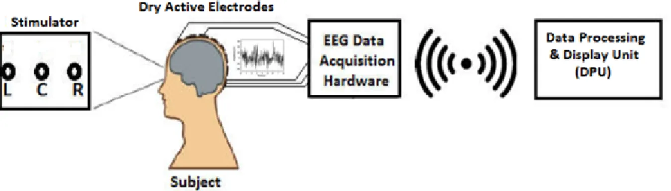
Before going into the design and implementation of the parts mentioned in Figure 2.1, a brief overview of the system functionality is presented. The proposed BCI system uses three LEDs (named as Left (L), Center (C) and Right (R) w.r.t the subject) as visual stimuli. Each LED flickers at one of the three different frequencies in case of f-VEP experiment or according to the pseudo-random code sequence in case of c-VEP experiment. The differential EEG data is recorded using dry active electrodes from O1, O2, and Oz positions with respect to the reference position FCz. The data acquisition is done using a 4-channel EEG data acquisition hardware. Fourth channel is dedicated for the marker signal in case of c-VEP experiments. The acquired EEG data is then processed in real time to estimate the subject’s focus. In simple words, the subject is asked to focus at one of the LEDs and our system estimates his/her focus (L, C or R) in real time. This complete flow of information is described in Figure 2.2. The detailed design and implementation is discussed in the upcoming sections.
Figure 2.2: Flow diagram showing the flow of data through the system
2.1
Stimulator
The purpose of the stimulator is to provide the visual stimulus to the brain, in response of which brain generates specific signals used to classify the targets. Since the proposed BCI system is based on steady state visually evoked potentials (SSVEP), the stimulator is designed in such a way to provide both the frequency modulated VEP (f-VEP) and code modulated VEP (c-VEP) stimulations accord-ing to the requirement of the experiment.
The proposed stimulator design consists of three LEDs driven by a battery powered, microcontroller based circuit. So the whole stimulator design can be disintegrated into three parts (battery, LEDs, and stimulator circuit) as described in the upcoming paragraphs:
2.1.1
Battery
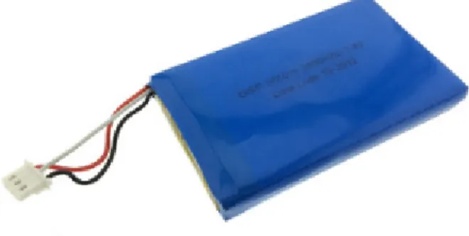
To power up the whole stimulator, a 7.4V, Lithium-Polymer (LiPo) rechargeable battery is used. It is a Lithium-ion rechargeable battery using the polymer as electrolyte instead of liquid. The representative image of the battery is shown in Figure 2.3
Figure 2.3: The 7.4V Lithium polymer rechargeable battery The battery has following key features:
a. It contains two battery cells placed in series having nominal voltage of 3.7 V each making the total nominal voltage of 7.4 V .
b. Its rated capacity is 2400 mAh.
c. Discharge cut-off voltage = 6.0 V . It means that it can be used for the output voltage as low as 6.0 V . If the current is drawn after reaching this low threshold, the battery may become inactive and will not be able to recharge.
d. It can be charged by the DC supply of 8.4 V and 0.5 × C = 1.2 A where C is the rated capacity of the battery.
e. It can be discharged at 0.2 × C = 0.48 A until the voltage drops to 6.0 V . f. It is 80.5 mm in length, 50.5 mm in width and 12 mm in thickness.
2.1.2
Light Emitting Diodes (LEDs)
Three in number 3W power LEDs, emitting white light are used as the stimu-lation source. They are cheap and easily available from the local market. The representative image of the LEDs is shown in figure 2.4
Figure 2.4: The representative image of the Power LEDs used in the stimulator Some of the key features of the LEDs are described below:
a. Light color = white
b. Forward voltage drop = 3.0 V to 3.2 V c. Viewing angle = 125 ± 5◦
e. Bulb diameter = 6 mm
f. Mounting type: Surface mount with 5 mm total height
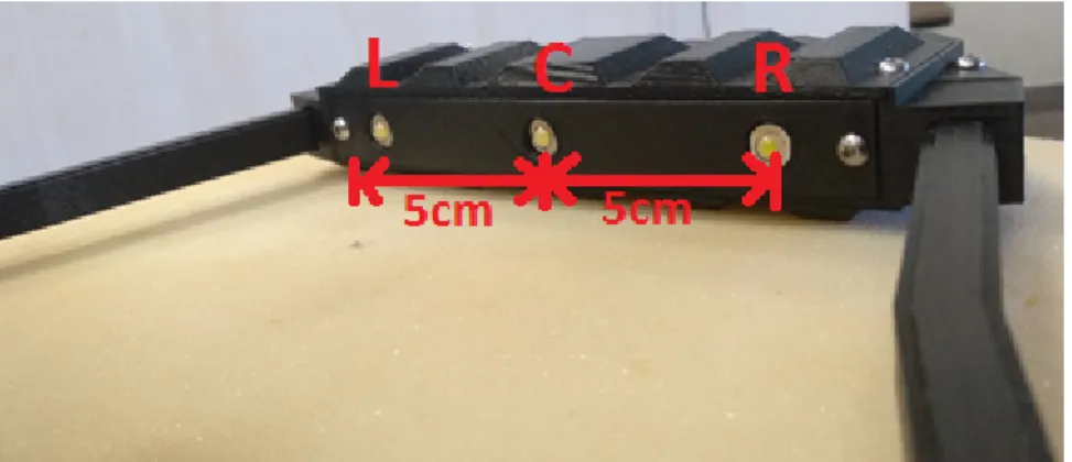
The LED array was formed to place the LED targets as close to each other as possible so that gaze shifting would require minimal eye movement. For less than 5 cm separation between the LEDs, it becomes difficult for the user to focus on certain LED target because the neighbouring LED generates the flickering perception different from that of target LED in the user’s mind. For the separa-tions greater than 5 cm, the results were neither deteriorated nor improved. So, a separation of 5 cm between the consecutive LEDs is used.
Similarly for the distance of LEDs less than 15 cm from the forehead, the user feels it difficult to focusing the target LED. For more than 15 cm distance of LEDs from the forehead, the results did not change. So, The three LEDs are arranged in the form of a horizontal array formed in such a way that they are 5 cm apart from each other keeping the distance of the whole array from the subject’s forehead as 15 cm. The LEDs array mounted on the 3D printed headset is shown in figure 2.5.
Figure 2.5: The array of three LEDs (marked as L, C, and R) mounted on the 3D printed headset
In the proposed BCI system, these LEDs are driven by a small current i.e. 13.3 mA for each LED in the ON state. Since they are driven by square waves with 50% duty cycle or by pseudo-random code having nearly equal number of zeros and ones, the average current for each LED becomes 6.65 mA amounting
to the total current of about 20 mA. This current requirement is fulfilled using the battery as mentioned in section 2.1.1.
2.1.3
Stimulator Circuit
The basic job of the stimulator circuit is to drive the three LEDs described in 2.1.2. There are two types of visual stimuli required depending on the type of VEP modality (f-VEP or c-VEP) used for classification. So, the two different stimulation signals are generated by designing a programmable stimulator circuit. The details of its hardware and software parts are discussed in the following paragraphs:
2.1.3.1 Programmable hardware Circuit
It is a microcontroller based circuit used to generate the drive signals for the stimulator LEDs. It employs Atmel AT M EGA328P microcontroller which is a high Performance, Low Power, 8-Bit, AVR Microcontroller. It is available in 28-pin DIP (dual in-line package) and 32-pin TQFP (thin quad flat package) packages. It is also used in Arduino UNO which is a very popular open source, programmable, prototyping platform. We have used 32-pin TQFP package as shown in Figure 2.6.
Some of the main features of AT M EGA328P microcontroller are listed below:
a. It has advanced RISC (Reduced instruction set computing) architecture having 131 powerful instruction. Most of these instructions are executed in single clock cycle time
b. Its throughput can go up to 20 million instruction per second (20 MIPS) at 20 MHz clock
c. It has two 8-bit timers and one 16-bit timer with separate pre-scalar and compare modes.
d. It has three options to communicate with other devices: (i) programmable serial USART (Universal Synchronous Asynchronous Receiver Transmitter commonly known as RS232),(ii) Master/slave SPI (Serial Peripheral Inter-face), and (iii) 2-wire I2C (Inter-Integrated Circuit) interface
e. It has built-in Power-on reset and internally calibrated 8M Hz oscillator f. It has 23 programmable input output (I/O) lines. It also has 8 channel,
10 bit resolution analog to digital converter which can achieve maximum sampling rate of 9615 samples/s at 16 MHz clock.
g. It can operate from 1.8V − 5.5V DC power supply
Since the microcontroller can be powered up by 1.8 − 5.5V DC supply and we have used 6V − 8.4V DC battery as stated in 2.3, a low cost, linear voltage regulator (LM7805) is used to provide fixed 5 V to the microcontroller. A 16 M Hz quartz crystal is also used with the microntroller to provide external clock source for its smooth operation. The complete schematic design of the programmable hardware circuit for the stimulator is shown in Figure 2.7.
The programmable microcontroller based circuit is not only responsible for the generation of drive signals for the LEDs but also for the generation of synchronous marker signal in case of c-VEP stimulation. The led “L” is driven by the micro-controller’s pin P D6, LED “C” by P D7 and LED “R” by P D5. The synchronous
Figure 2.7: Schematic of the stimulator circuit
c-VEP marker signal is generated at the pin P B2 of the microcontroller. A select button (ON/OFF) is integrated with the P D2 pin of microcontroller in pull-up configuration to select among the f-VEP or c-VEP stimulus generation. The provision of 4 extra digital I/O pins is also provided in the stimulator hardware design for future utility. These extra I/O pins will provide the ease to extend the system from 3-target to 7-target system.
The circuit’s schematic is converted into a single sided PCB layout using a free PCB design tool named as DipTrace. The PCB layout is given in Figure 2.8.
Figure 2.8: Layout of the stimulator circuit using DipTrace
The PCB layout was then printed using prototype PCB printing facility of Bilkent University’s EEE department. The printed PCB is shown in the Figure 2.9.
Figure 2.9: The stimulator circuit layout printed on a PCB
The PCB is 120 mm long and 21 mm wide. The final shape of the PCB after soldering of all the components is shown in Figure 2.10.
Figure 2.10: The stimulator circuit implemented on a 120 mm × 21 mm PCB
2.1.3.2 Microcontroller programming for f-VEP Stimulation
f-VEP is a type of SSVEP paradigm in which each target flickers at different frequency and the brain generates the EEG activity in visual cortex having fun-damental stimulus frequency and its harmonics. It has been discussed in detail in 1.1.3.4.
Since the proposed BCI system is a three target system, three signals having frequencies corresponding to the time periods of 50 ms, 44 ms and 38 ms are generated using the microcontroller. For the time periods to be exactly the integer multiples of of 1 ms, we have used timer interrupt which is running at 1 KHz i.e. it interrupts after every 1 ms. So we keep track of the timer interrupts and toggle the relevant digital I/O pins after corresponding half time period i.e. 25 ms, 22 ms and 19 ms. So the frequencies generated are 20 Hz, 22.73 Hz and 26.32 Hz and they are taken out from P D6, P D7 and P D5 pins of the microcontroller respectively. The programming code is written in an open source integrated
development environment (IDE) provided in Arduino-1.8.5. The source code is provided in the CD attached to this thesis whose contents are explained in Appendix B.
The OFF state of the button present at the outer body of the stimulator will signal the microcontroller to generate f-VEP stimulation signals. These signals are measured using the oscilloscope for verification purpose. The snapshots of the oscilloscope screen are shown in Figure 2.11.
Figure 2.11: The oscilloscope screen shots showing LED drive signals for f-VEP stimulation (20 Hz, 22.73 Hz, and 26.32 Hz square waves)
2.1.3.3 Microcontroller programming for c-VEP Stimulation
In case of c-VEP modality, the stimulus signal is a pseudo-random code (array of 1’s and 0’s) instead of a single frequency. It is noted in the literature that maximum length sequence (m-sequence) is the most commonly utilized sequence in c-VEP based BCI systems [43]. A binary m-sequence can be generated by the
use of shift registers having maximal linear feedback. It is very useful in the c-VEP based BCI systems because its autocorrelation function is very close to the unit impulse function and it is found to be nearly orthogonal to its time shifted versions [43].
We have generated a 15 bit binary m-sequence using MATLAB (code is given in the attached CD). The generated sequence is “100110101111000”. This is the code for one LED. The codes for other two LEDs are obtained by circularly shifting the above sequence by 5 and 10 bits respectively. So the three codes for the LEDs are:
a. m-sequence1 = 100110101111000 b. m-sequence2 = 110001001101011 c. m-sequence3 = 010111100010011
The correlation between these sequences is −0.0714, which is much close to zero meaning that all the three sequences are very close to being uncorre-lated/orthogonal. In the proposed design of microcontroller code, the bit length is set as 10 ms which means that the 15 bits code will take 150 ms time. These three sequences are generated on P D6, P D7 and P D5 pins of the microcon-troller driving L, C and R LEDs respectively by using timer interrupt running at 1 KHz. So each bit of the code is sent out to the respective I/O pin after 10 interrupts. A 6 ms long marker pulse is also generated at the P B2 pin of the microcontroller at the onset of each 15-bit m-sequence. The microcontroller code for the generation of these m-sequences is given provided in the attached CD (details about CD are given in Appendix B).
The ON state of the button present at the outer body of the stimulator will signal the microcontroller to generate c-VEP stimulation signals. These signals are measured using the oscilloscope for verification purpose. The screen-shots are given in Figure 2.12.
Figure 2.12: The oscilloscope screen shots showing LED driving drive signals for c-VEP stimulation (three pseudo-random m-sequences)
2.2
Dry Active Electrodes
There are two major types of electrodes being used for EEG recordings called dry electrodes and wet electrodes. As is clear from the names, the dry electrodes do not need any conductive gel between the skin and the metal body of the electrode while wet electrodes need such gel.
As the EEG signal amplitude is of the order of few µV , the transportation of this signal to the data acquisition hardware becomes very difficult because little interference coupling to the cables carrying these signals may ruin the signal. 50/60 Hz line’s capacitive coupling with the subject’s body is also present to interfere with the signal. So, it becomes a challenge to transport the poor EEG signal from the electrode to the data acquisition system. These interferences can be mitigated by the use of wet gel electrodes but they have their own limitations. In other words, they cannot be used for long term recordings as the signal quality goes low as the gel dries out [83]. Also, the wet gel produces discomfort to the
subject and repetition of experiments becomes difficult due to exhaustive skin preparation procedures [83] and post experiment washing activities.
To overcome these problems, active electrodes (AE) are suggested in the litera-ture [84],[85],[86]. An active electrode (AE) locally amplifies/buffers the µV level EEG signal before driving any cabling. These buffers/amplifiers are put just next to the skin electrode contact minimizing the path between the skin and the active circuit. This minimal path length mitigates/minimizes the line interference [83]. The low output impedance of an AE mitigates cable artifacts [83] thus enabling the use of high-impedance dry electrodes for greater user comfort.
In the proposed BCI system, we have used Ag/AgCl dry electrodes from Open-BCI with a unity gain amplifier (buffer). From now on, the buffer circuit will be called as active circuit. So, combining active circuit with the dry electrode makes the dry active electrodes (DAE). The active circuit is built by using the circuit shared in OpenEEG project (a free platform to share the ideas to build low cost EEG devices “http://openeeg.sourceforge.net/doc/”). Both of these parts are explained in the upcoming paragraphs.
2.2.1
Dry electrodes
In the proposed BCI system, Ag/AgCl dry electrodes from openBCI (an open source biosensing tools manufacturer “https://openbci.com/”) are used. Figure 2.13 shows the dry electrode in parts and in assembled form.
2.2.2
Active Circuit
As we have mentioned above that the active circuit is used next to the skin elec-trode contact to keep the signal integrity intact and get rid of the application of wet gel. The design of the active circuit is quite simple because it is just a unity gain amplifier called buffer. As mentioned earlier, the circuit design of the active circuit is taken from OpenEEG project which provides free techniques
Figure 2.13: A sample of dry electrode from OpenBCI (a) shows the individual parts and (b) shows the assembled form of the spring loaded dry electrode to design low cost EEG devices at home. The buffer design uses Texas Instru-ment’s TLC272 op-amp which is a low noise, high input impedance precision operational amplifier. It also provides good CMRR (typically 80dB). The active circuit schematic is given in Figure 2.14.
Figure 2.14: Schematic of the active circuit (a unity gain amplifier implemented using TL272 op-amp). The bottom op-amp(U1.2) is of no use in the ciruit. It is placed because the IC package has two op-amps.
The schematic is then converted to a small circular PCB (25 mm diameter) layout using free PCB design tool ”DipTrace”. The PCB layout and its actual
shape is shown in Figure 2.15.
Figure 2.15: (a) Active circuit layout (b) active circuit PCB (top view) (c) active circuit PCB (bottom view) (d) The complete dry active electrode having dry electrode and active circuit wrapped in thin copper sheet to provide shielding to the circuit
2.3
EEG Data acquisition hardware
In the proposed BCI system, a 4-channel, battery powered EEG data acquisition hardware is designed which can support sampling rates ranging from 250 to 2000 samples/sec for each channel. It can be further divided into four subsections as follows:
a. EEG Amplifier Unit b. Microcontroller unit
c. Wifi Transmitter and Receiver d. Power supply unit
2.3.1
EEG Amplifier Unit
The EEG amplifier unit is the first interface of the EEG signal with the data acquisition hardware after the active electrode and some cables. The purpose of this unit is to amplify the poor EEG signal to some extent and digitizes it using analog to digital converter. At this stage, the analog EEG signal is converted into digital domain and is forwarded to the next stage. Since the EEG signal is accompanied with a lot of noise and unwanted artifacts, the incoming signal is first passed through a first order passive low pass filter (built up by capacitor and resistor) and then amplified by giving a small gain of 24. The EEG signals are ac-quired as differential signal to get rid of the common mode unwanted signals. All of these characteristics are combined in a single EEG acquisition chip ADS1299 manufactured by Texas Instruments. In our proposed BCI system, 4-channel version of the chip i.e. ADS1299 − 4 is used for the EEG signal acquisition. Some of the main features of this chip (referred to as ”EEG chip” throughout the document) are listed below:
a. It has four low noise programmable gain amplifiers (PGAs) whose gains can be adjusted as one of the values from 1, 2, 4, 6, 8, 12, or 24.
b. It has 4-channel, simultaneous sampling, analog to digital (A/D) converter having 24-bit resolution
c. It can sample the signals at sampling rates of 250, 500, 1000, 2000, 4000, 8000 or 16000 samples/second
d. It provides very high common mode rejection ratio (CMRR) of −110 dB. e. It can use external as well as internal reference for A/D conversion.
f. It has built in oscillator to provide clock source to the circuit internally g. It can use unipolar as well as bipolar supplies. Since it is mixed signal
device, its analog side needs 4.75 − 5.25 V and digital side needs 1.8 − 3.6 V supplies.
h. It gives digital data output through serial peripheral interface (SPI)
i. It has the provision to connect the input channels to the internally generated test signals, temperature measurement or lead-off detection.
i. It is available in 64-pin Thin Quad Flat Package (TQFP).
The real look of the EEG chip (64-pin TQFP chip) is given Figure 2.16
Figure 2.16: The 4-channel EEG data acquisition chip (ADS1299-4) in 64-pin TQFP package
2.3.2
Microcontroller Unit
The purpose of the microcontroller unit in this section is to collect the data from EEG chip using SPI protocol and forward them to the wifi transmitter module. We have used Atmel ATMEGA328P microcontroller to configure the EEG chip for certain parameters like sampling rate, start and stop data acquisition. The microcontroller is also responsible for the communication with EEG chip and Wifi transmitter. The key features of the microntroller are discussed in section 2.1.3.1.
The microcontroller needs to communicate with the EEG chip but the micro-controller works on 5V logic level while EEG chip’s digital side works on 3.3V logic level. So, a logic level shifter chip ( Texas Instrument’s SN74LVCC3245ADW) is used between the microcontroller and the EEG chip for reliable communication. The microcontroller is supposed to (i) configure sampling rate, start and stop of the data conversion, setting the gain of the EEG amplifiers, connecting input
channels with the desired functionalities (ii) receive digital EEG data output from the EEG chip. It configures and controls the EEG chip by sending some commands to the EEG chip or writing to some of its internal registers. The complete details are available in the datasheet of ADS1299 chip (provided in the attached CD). Some important configurations which we have used in our design are described as follows:
a. It can control the EEG chip by sending start, stop or reset commands. These are single byte commands which the EEG chip can understand and act accordingly. It sends 00001000 to start, 00001010 to stop, and 00000110 to reset the EEG chip. The commands are sent using SPI protocol at 8 M Hz clock generated by the microcontroller.
b. For the selection of sampling rate, the microcontroller writes some values to the ”CONFIG1” register of the EEG chip. This register is located at 01 hex location of the EEG chip and needs 96 hex to set 250 samples/sec (SP S), 95 hex for 500 SP S, 94 hex for 1000 SP S, and 93 hex for 2000 SP S. We have tested our system for a maximum of 2000 SP S.
c. There are separate registers to configure the signal connections of each analog input channel and setting their corresponding amplifier’s gain. These registers are named as “ch1set”, “ch2set”, “ch3set” and “ch4set”. They are located at register addresses of 05 hex, 06 hex, 07 hex, and 08 hex respectively in the EEG chip. They are given the value of 68 hex for the connection of the respective input channel to the standard EEG electrodes while they get the value of 6D hex if we want to connect them to the test signal. These values are calculated by fixing the PGA gains at 24.
d. The test signal parameters are configured by setting the ”CONFIG2” reg-ister located at 05 hex address in the EEG chip. ”CONFIG2” regreg-ister is given the value of D4 hex for the internally generated test signal having frequency equal to the clock frequency divided by 221.
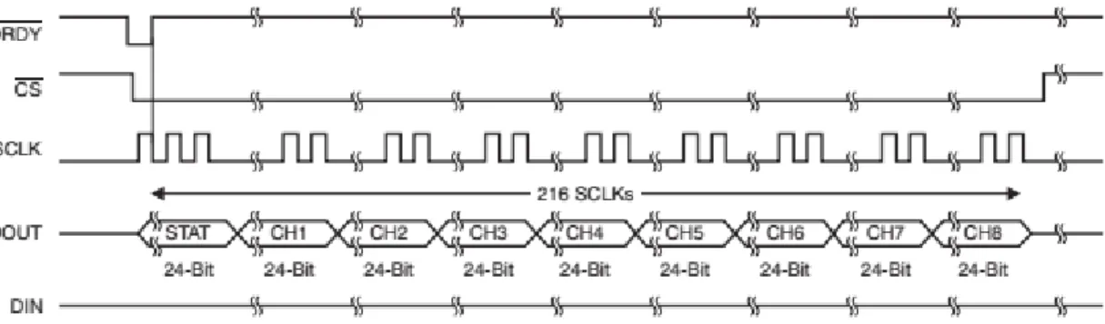
The second part of the microcontroller’s communication with the EEG chip is to receive the digital data through SPI. The EEG chip outputs the data in the
form of 15 byte array. This array contains 3 bytes of status registers and 3 bytes for each of the four channels data. To get this data, the microcontroller waits for the DRDY pin of the EEG chip to get low. As soon as it detects the falling edge of the DRDY pin it makes CS pin low and starts generating an 8 M Hz SCLK signal. The EEG chip then clocks out the data on rising edge of SCLK.
We have used OpenBCI’s arduino based library to develop the code for the microcontroller to communicate with the EEG chip (the library files are provided in the attached CD). The microcontroller’s program to communicate with the EEG chip is written in Arduino-1.8.5 IDE (the source code is also provided in the attached CD explained in Appendix B). Figure 2.17 shows the timing diagram (taken from the datasheet of the ADS1299 chip) of the communication protocol to exchange data with the EEG chip .
Figure 2.17: The timing diagram of the communication protocol used to exchange data with the EEG chip (ADS1299)
When the microcontroller receives this data, it forwards it to the wifi trans-mitter module using standard RS232 serial communication protocol at the baud rate of 1 Mbps.
2.3.3
Wifi Transmitter and Receiver
Since we have proposed a wireless BCI system, a wifi communication is used to forward the EEG data to DPU. ESP8266 wifi transceiver board which is an open source Arduino based prototyping platform is used as wifi transmitter (wifi Tx)
module. On the receiving side, “Node-microcontroller” which is also an Arduino compatible open source, prototyping platform is used as wifi receiver (wifi Rx) module. The Node-microcontroller is also an ESP8266 based wifi transceiver having an additional feature of built-in serial to Universal Serial Bus (USB) con-version to communicate with the computer. The node microcontroller and the ESP8266 wifi module are shown in Figure 2.18.
Figure 2.18: Real look of the node microcontroller (node MCU) used as wifi Rx module and ESP8266 wifi module used wifi Tx module in the proposed BCI system
The wifi Tx receives data from the microcontroller via RS232 at the baud rate of 1 M bps, makes a packet of 960 bytes, and sends it to the remote wifi Rx via user datagram protocol (UDP). The wifi Rx receives this data packet and forwards it to the data processing unit (DPU) via RS232 serial communication at a baud rate of 230400 bps. This is the forward link of communication. The reverse communication link includes sending of command/s to the microcontroller via wifi transmitter module to start the data acquisition. Upon reception of this start command from the DPU, the microcontroller configures the EEG chip for the start of data conversion. In simple words, both the wifi modules are working as wifi-UART bridge.
Some of the key features of the ESP8266 wifi module are listed below: