Patch Antenna with Multiple Slits and Circular
Shaped
Furkan Atalah
Department of Electrical & Electronics Engineering Istanbul Commerce University, Istanbul, Turkey
Mustafa Imeci
Department of Electrical & Electronics Engineering Yildirim Beyazit University, Ankara, Turkey
Oguzhan Gungor
Department of Electrical & Electronics Engineering Selcuk University, Konya, Turkey
S. Taha Imeci
Department of Electrical & Electronics Engineering Int. University of Sarajevo, Bosnia and Herzegovina
Tahsin Durak
Department of Technology, NSU, Norfolk, VA
Abstract—In this paper, a circular shaped ground-fed patch antenna is designed, simulated, built and tested. The operating antenna frequency is 14.6 GHz with -15.68 dB input and 8.14 dB gain. Furthermore, the antenna have multiple slits in a circular main body, and also supported with triangle and rectangle shapes. The measurements of the fabricated patch antenna matches the simulation results.
Keywords—Circular shaped antenna, microstrip patch antenna, single resonance.
I. INTRODUCTION
The recent revolution in electronic circuits pressured the antenna designers to come up with small, lightweight and low cost radiating structures. This requirement led to the invention of several antenna structures, of which, printed microstrip antenna received a lot attention in recent years [1].
Due to their low-profile and conformable geometry, they are widely used as embedded antennas in handheld wireless devices and military equipment [2]. However, intensive research is required to improve the inherent disadvantages of this antenna, such as: narrow bandwidth, low efficiency, spurious feed radiation, poor polarization purity and limited power capacity [3].
A microstrip patch antenna is made up of a radiating patch on one side of dielectric substrate while has a ground plane on the other side [4]. Substrate is located over a large metallic sheet called ground plane [5]. The suitable substrate is the one with a low dielectric constant, a large thickness compared to the operating wavelength and low loss because in the realization of microwave circuits, the goal is to minimize the radiation of the line in free space and therefore have a substrate which the electromagnetic energy is concentrated in the dielectric (more precisely in the cavity formed by the metal strip and the ground plane). So a thick substrate increases the power radiated by the antenna, reduces losses by Joule effect and improves the
bandwidth of the antenna. Permittivity of substrate is a critical parameter in controlling band width, efficiency, and radiation pattern of patch antenna. However, higher dielectric constant also reduces bandwidth and radiation efficiency [6].
Microstrip patch antennas are usually designed to eliminate the imaginary part of the input impedance. Edge fields are also important and they bring an additional length to the antenna. This length depends on the relative permittivity of the dielectric, dielectric height and patch width [7].
Microstrip patch antennas are versatile structures which can be modified by adding simple slots either “parallel to radiation edges” or “parallel to resonance edges” in the design structure to overcome selected limitations of conventional patch antennas. The antenna can provide improved bandwidth enhancement, under certain conditions, while maintaining many of the desirable features of conventional patches. However, it is difficult to determine or predict resonant frequencies and bandwidths especially when the changes in terms of position of slots and the widths of slots are relatively small. As a result, machine algorithms can be applied to interpret the relationship between inputs and outputs of the system. Depending on the problem, the appropriate algorithms can be selected to estimate the outputs [8].
During the design process, the motivations involved in selecting different antenna components are as follows: Microstrip antennas can be incorporated in various geometries, such as: rectangular, circular, triangular, annular patches and others [9].
Circular patch is the second most popular shape and can be easily analyzed and modified to produce a range of impedance values, radiation patterns and frequencies of operation. Among the four most popular feed techniques, coax-fed method has low spurious feed radiation and is easy to match [10].
Organization of this paper is as follows: the design steps are described in Section II, results and conclusion are presented in Section III of the paper.
Submitted On: September 30, 2018
II. DESIGN STEPS
The size of the antenna is 20 × 31 mm. Substrate material is FR- 4 and the thickness is 1 mm (𝜀𝑟= 4.4, dielectric loss tangent
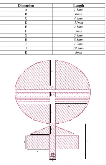
= 0.0018 mm). The thickness of air in simulation is taken 3 times of the thickness of the FR-4, (3 mm). The top view of the antenna is in Fig. 1, and Table I shows the antenna parameters and the values.
TABLE I. ANTENNA PARAMETERS AND VALUES
Dimension Length A 1.5mm B 6mm C 4.3mm D 11mm E 2.5mm F 5mm G 5.8mm H 8.3mm I 1.2mm J 19.3mm K 8mm
Fig. 1. Top view of the simulated circular antenna.
III. SIMULATION AND PARAMETRIC STUDY
In the initial design, we had circular shape and a standard port, there was almost no gain with -35 dB reflection coefficient at 14.6 GHz. Later, triangular sections and square sections are added. Then we added some slits in circular shape, as a result of successive iteration of simulations, changing the feeding location and relocating the triangular and rectangular shapes to design, we optimized the antenna. As a result of optimization, lower input matches and high gains are maintained. In Fig. 2, input reflection coefficient, S11 is shown at 14.6 GHz, and -15.69 dB magnitude was found as simulation and -13.9 dB as measurement. In Fig. 3, gain graph is shown and +8.14 dB simulated and 6.1 dB measured result was found at 14.6 GHz. Fig. 4 has the manufactured antenna. Table II shows variations of gap between slits.
Measurement is carried out in Yeditepe Universities testing facility. Measurement setup is shown in Fig. 5.
Fig. 2. S11 graph.
Fig. 3. Radiation pattern (gain) graph.
Fig. 4. Top view of the produced antenna.
ACES JOURNAL, Vol. 34, No. 2, February 2019
TABLEII. FREQUENCY-GAIN-INPUT MATCH WITH MODIFIED GAP
Gap between Slits Frequencies Gain (dB) Input Match (dB)
0.25 10.5 GHz 6.35 –16.8 11.3 GHz 7.22 –14.72 0.5 10.7 GHz 6.68 –15.77 11.9 GHz 7.32 –10.5 0.75 11.9 GHz 6.88 –8.5 14.6 GHz 8.14 –15.69 1 12.7 GHz 5.33 –8.45 13.5 GHz 5.77 –9.25 14.44 GHz 6.11 –18.22
Fig. 5. Measurement setup.
IV. CONCLUSION
Our aim is to find higher gain values for fabrication of circular shaped patch antenna for single band operations by simulating with different geometrical values mentioned in the article. A comprehensive parametric study has been carryout out. Throughout our design steps in this conclusion part of this project we can say that designing circular ring shaped antenna is not easy due to limitations, dielectric material type, gain - frequency relation, feeding type and technique. Even small changes on the antenna may have drastic outcomes, these changes have to be noted each time and avoid being applied again to cause further confusion during design. It should also be noted that in circular ring shaped patch antennas making slits, gaps inside of circular ring and pincering current to the sides by increasing the length of slits and gaps increases gain.
By varying the thickness, different parameters of the designed antenna can be optimized. Proposed antenna can be used in different applications such as in wireless communication and S band applications.
The simulations results are performed using Sonnet software [11].
ACKNOWLEDGMENT
We would like to thank Sonnet Software and Yeditepe
University for their services.
REFERENCES
[1] A. Dalli, L. Zenkouar, and S. Bri, “Comparison of circular sector and rectangular patch antenna arrays in C-Band,” Journal of Electromagnetic Analysis and Applications, vol. 4, no. 11 pp. 457-467, 2012.
[2] S. Malisuwan, J. Sivaraks, N. Madan, and N. Suriyakrai, “Design of microstrip patch antenna for Ku-band satellite communication applications,” International Journal of Computer and Communication Engineering, vol. 3, no. 6, Nov. 2014.
[3] A. Thakur, M. Chauhan, and M. Kumar, “Effect of substrate relative dielectric constant on bandwidth characteristics of line feed rectangular patch antenna,” International Journal of Engineering Science Invention Research & Development, vol. 1, iss. 10, e-ISSSN: 2349-6185, Apr. 2015. [4] R. K. Sharan, S. K. Sharma, A. Gupta, and R. K. Chaoudhary, “An edge tapered rectangular patch antenna with parasitic stubs and slot for wideband applications,” Wirel. Pers. Commun., 86, pp. 1213-1220, 2016. [5] O. Mahmoodian, “Enhancing microstrip patch antenna performance by using high impedance surfaces (HIS),” Bull. Env. Pharmacol. Life Sci., 5(6), pp. 11-14, 2016.
[6] A. Bendaoudi and Z. Mahdjoub, “Comparative study of patch antenna loaded with slot split-ring resonators on different substrate materials,” Photon Network Communication, vol. 35, pp. 195-203, 2018.
[7] R. E. Munson, “Conformal microstrip antennas and microstrip phased arrays,” IEEE Trans. Antennas Propagation, vol. AP-22, pp. 74-78, Jan. 1974.
[8] M. A. Layegh, C. Ghobadi, and J. Nouriia, “The optimization design of a noval slotted microstrip patch antenna with multi-bands using adaptive network-based fuzzy interference system,” MDPI Technologies, vol. 5, pp. 174-185, Apr. 2017.
[9] A. Deshmukh, V. Pandit, R. Colaco, and R. Doshi “Dual band dual polarized modified circular microstrip antenna,” International Conference on Circuits, Systems, Communication and Information Technology Applications (CSCITA), 2014.
[10] R. Garg, P. Bhatia, I. Bhal, and A. Ittipibon, Microstrip Antenna Design Handbook. Artech House, 2001.
[11] Sonnet Suites, ver. 17.52, www.sonnetsoftware.com
Furkan Atalah completed B.Sc. degree in Electrical and
Electronics Engineering, Istanbul Commerce University, Istanbul, Turkey. His current research areas are, microwave antennas and circuits design.
Mustafa Imeci completed B.Sc. degree
in Electrical and Electronics Engineering, Yildirim Beyazit University, Ankara, Turkey. His current research areas are, microwave antennas and digital signal processing.
Oguzhan Salih Gungor is pursuing his
B.Sc. degree in Electrical and Electronics Engineering, Selcuk University, Konya, Turkey. His current research areas are, microwave antennas and couplers.
Şehabeddin Taha İmeci received the B.Sc.
degree in Electronics and Communications Engineering from Yildiz Technical Uni-versity, Istanbul, Turkey in 1993, and the M.S.E.E. and Ph.D. degrees from Syracuse University, Syracuse, NY in 2001 and 2007, and Associate Professorship degree from Istanbul Commerce University, Istanbul Turkey in 2014, respectively. Imeci was appointed as Full Professor in Int. Univ. of Sarajevo in Nov. 2017. He is working as Vice-Rector in Sarajevo. He was with Anaren Microwave Inc., East Syracuse, NY from 2000 to 2002, and Herley Farmingdale, New York from 2002 to 2003, and PPC, Syracuse, NY from 2003 to 2005, and Sonnet Software Inc., Liverpool, NY from 2006 to 2007. He was a Teaching Assistant in the Department of Electrical Engineering and Computer Science at Syracuse University from 2005 to 2006. He authored two books and published more than 150 papers. His current research areas are, microwave antennas and electromagnetic theory.
Tahsin Durak received his B.Sc. degree
in Electrical and Electronics Engineering from Gazi University, Ankara, Turkey in 1992, his first M.S degree in Electrical Engineering from Fairleigh Dickinson University, NJ, USA in 1998, his second M.S. and Ph.D. degrees in Electrical Engineering from Syracuse University, NY, USA in 2001 and 2008 respectively. From 2000 until 2001,
he was with Philips Broadband Networks, Manlius, NY, USA. He was a Teaching Assistant in the Department of Electrical Engineering and Computer Science at Syracuse University from 2001 to 2004. He joined Norfolk State University, Norfolk, VA, in 2010 as an Assistant Professor. Since 2014, he has been working in industry as a Staff Engineer, Electrical Engineering Manager and Engineering Director. He continues to teach at local universities as an Adjunct Faculty. He has several US patents in the area of Microwave, RFID and IIOT. His current research areas are microwave antennas, RFID technologies, IIOT solutions, industrial automations, remote controls, industrial machine to machine communication techniques and protocols. Durak has been a Member of the IEEE.
ACES JOURNAL, Vol. 34, No. 2, February 2019