THREE DEGREE OF FREEDOM LEG DESIGN FOR QUADRUPED ROBOTS AND FRACTIONAL ORDER PID (PIλDµ) BASED CONTROL
1Muhammed Arif ŞEN , 2Veli BAKIRCIOĞLU , 3Mete KALYONCU
1 ,3 Konya Technical University, Engineering and Natural Sciences Faculty, Mechanical Engineering Department,
Konya, TURKEY
2 Aksaray University, Technical Science Vocational Education and Training School, Aksaray, TURKEY
1[email protected],2[email protected],3[email protected]
(Geliş/Received: 16.09.2019; Kabul/Accepted in Revised Form: 10.10.2019)
ABSTRACT: Quadruped robots are legged mobile robots that increase their popularity in robotic and control areas due to their complex dynamic structure with high mobility in different terrain conditions compared to wheeled systems. In this study; A 3-DoF linear leg model and its control are provided in order to enable quick and effectively simulate about on such subjects that walking planning, foot trajectory design and body stability control of the robot. A realistic physical model with parameters such as the dimensions, masses, inertia of limbs and the stiffness and damping values of joints is designed and simulated on Matlab/Simulink/Simscape environment. By taking into account the angular position ranges of the joints required for the robot to perform a standard step trajectory during the walk, the linear State-Space model of the system (torque input-angular position output) is obtained using the linearization tools over the physical model. The unit step responses of the physical model are compared with the obtained linear model responses under constant torque input and it is understood to give similar results with small error values. Using the linear model, the angular position control of the system is achieved with PIλDµ controllers designed by selecting various parameters of fraction orders as comparatively the classical PID controller. Simulation results are presented and investigated.
Key Words: 3-DoF quadruped robot leg, realistic model, linear modelling, PIλDµ controller
Dört Ayaklı Robotlar için Üç Serbestlik Dereceli Bacak Tasarımı ve Kesir Dereceli PID (PIλDµ) Tabanlı Kontrolü
ÖZ: Dört ayaklı robotlar, tekerlekli sistemlere kıyasla farklı arazi şartlarında yüksek hareket kabiliyetine sahip, karmaşık dinamik yapısı nedeniyle robotik ve kontrol alanında popülerliğini artıran, bacaklı mobil robotlardır. Bu çalışmada; yürüyüş planlaması, adım yörüngesi tasarımı, gövdenin denge kontrolü gibi konularda hızlı ve etkili bir benzetim yapabilmek amacıyla, üç serbestlik dereceli doğrusal bacak modeli ve kontrolü sunulmuştur. Uzuv boyutlar, kütle, atalet, eklem sertlik ve sönüm değerleri vb. gibi dinamik parametreleri içeren gerçekçi bir fiziksel model Matlab/Simulink/ Simscape’de tasarlandı ve benzetimi gerçekleştirildi. Robotun yürüyüşü boyunca standart bir adım yörüngesini gerçekleştirmek için gerekli eklemlere ait açısal konum aralıkları dikkate alınarak, fiziksel model üzerinden doğrusallaştırma araçları kullanılarak, girişi tork-çıkışı açısal konum olacak şekilde, sistemin doğrusal Durum-Uzay modeli elde edilmiştir. Sistemin doğrusal model ile fiziksel modelinin, sabit tork girişine karşın birim basamak cevapları karşılaştırılmış ve küçük hata değerleri ile modellere ait cevapların birbirine benzer sonuçlar verdiği görülmüştür. Doğrusal model üzerinden sistemin, farklı kesir dereceleri seçilerek tasarlanan
PIλDµ kontrolcüleri ile açısal konum kontrolü, klasik PID kontrolcü ile karşılaştırmalı olarak gerçekleştirmiştir. Benzetim sonuçları sunulmuş ve değerlendirilmiştir.
Anahtar Kelimeler: 3-DoF dört ayaklı robot bacağı, gerçekçi model, doğrusal modelleme, PIλDµ kontrolcü
INTRODUCTION
In the field of robotics, there are a growing interest in quadruped (four-legged) robots that mimic the dynamic characteristics of biological organisms. They can walk with agile mobility by imitating the dynamics of animals such as dogs, cheetahs, horses, etc. The inadequate mobility and limited diversity of wheeled robots on uneven terrain are motivating studies on quadruped robots (Raibert, 1986). Increase experimental and simulation studies in this field; It contributes to the development of skills to perform dangerous tasks for people such as search and rescue and cargo transportation in civil and military applications (Baudoin and Maki, 2010).
In recent years, there have been several successfully developed quadruped robots. Among the most important of these; The robots developed by Boston Dynamics; starting with the basic-stone study BigDog (Raibert et al., 2008) and continuing with WildCat, LS3, Spot, SpotMini (Boston Dynamics Company, 2019), HyQ (Semini et al, 2010) and HyQ2Max (Semini et al., 2017) which are developed by Semini et al. in Istituto Italiano di Tecnologia Institute (IIT) and ANYmal (Hutter et al., 2012) and StarlETH (Hutter et al., 2017) which are developed by Hutter et al. in ETH Zurich Institute. Presently, Semini et al. continue to develop a robot called HyQReal to support people in challenging tasks and emergencies. Hutter et al. is working on a robot named ANYmal C, which can be used in industrial applications. However, the system's very degree-of-freedom, complex, and floating type of dynamic structure makes the progress of studies difficult about quadruped robots.
In general, the dynamic model of a robotic system is obtained through the Lagrange Energy methods. However, in a multi-degree of freedom systems, the computational complexity of the Lagrange Equations may require very long formations (Wisama and Etienne, 2002). For this reason, systems can be defined by a mathematical model equivalent to Matlab/Simscape (The MathWorks) software, which saves time and troubles, where its physical structure is specified by some variables such as mass, geometry and kinematic relationships between its components. Another disadvantage is the nonlinear character of the system. In order to perform a fast and effective simulation with linear controllers, the equations of motion need to be simplified. In this case, model linearization is a common strategy that facilitates controller design.
Velásquez-Lobo et al. (2013) presented a study on the modeling and linearization of a two-legged robot with Simscape. The system was controlled by a PID controller via a linear model transferred to Simulink. Similarly, Rossell et al. (2015) presented the linearization of the system with Simscape and Simulink environments on the solid model of the Stewart platform developed and presented the trajectory control of the system in comparison with PID and LQR controllers.
In this study, the mathematical linear model of a leg is obtained via a realistic physical CAD model including parameters such as physical size, mass, inertia, joint stiffness, and damping which designed in Simscape. And, PID and PIλDµ controllers are designed and implemented using realistic inputs in Simulink. For a closer simulation to real systems, the system is generally referred to as 3-DoF (hip limb - hip/pitch joint, thigh limb-hip/roll joint, knee limb - knee joint), unlike studies designed as 2-DoF. In addition, the linearization is carried out within the joint angular position ranges, which could perform a standard footstep trajectory of the leg.
After the introduction, the continuation of the study is organized as follows; modeling and linearization of the system is presented in Chapter 2, and the controller design is presented in Chapter 3. In Section 4, the comparatively simulation results are given and the results are evaluated in Section 5.
SYSTEM MODELING
In this section, the design of the robot leg, physical modeling, and obtaining the linear state-space model of the system are presented.
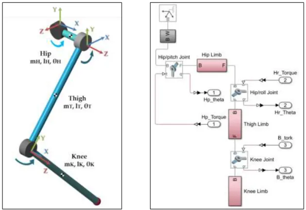
Simscape is a block diagram modeling environment for modeling and simulating mechanical systems using standard Newtonian force and torque dynamics. A realistic physical model of the robot leg is created by defining coordinate systems, initial conditions of joints, and kinematic constraints. Many parameters such as the kinematic structure of the leg, dimensions, and masses of limbs, damping and stiffness values of joints have been determined by considering HyQ (Semini et al, 2010) and HyQ2Max (Semini et al., 2017) robots. The system consists of hip, thigh, knee limbs, and angular movement joints (hip/pitch, hip/roll, knee) of these limbs.
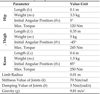
The physical model and block diagram of the system are given in Figure 1 and Figure 2. Table 1 shows the physical parameters of the system as well as the initial angular positions and the max. torque values of the joints are also given.
Table 1. System parameters and values
Parameter Value-Unit
Hip
Length (l
H) 0.1 m
Weight (mH) 3.5 kg
Initial Angular Position (θH) 5°
Max. Torque 120 Nm , T h igh Length (LT) 0.35 m Weight (mT) 5 kg
Initial Angular Position (θT) -45°
Max. Torque 245 Nm
Kn
ee
Length (LK) 0.4 m
Weight (mK) 1.5 kg
Initial Angular Position (θK) 85°
Max. Torque 250 Nm
Limb Radius 0.01 m
Stiffness Value of Joints (k) 70 Nm/rad Damping Value of Joints (b) 3 Nm/(rad/s)
Figure 1. Physical model of the leg Figure 2. Simscape block diagram of the leg After the physical model of the leg is created, the linear State-Space model of the system is obtained in order to make a fast and effective simulation in the studies such as gait planning of the robot, design of the foot trajectory, stability control of the main body. The reference joint angular position values (θHp = 5°
~ 25°, θHr = -45° ~ -15°, θK = 85° ~ 110°) required for the linearization process to achieve a standard footstep trajectory (height of step - 0.1 m and width of step - 0.2 m). The needful background such as angular position values and footstep trajectory are obtained from the authors' previous studies about single leg; the design and tuning of PID controller using the Bees Algorithm (Sen and Kalyoncu, 2015; Bakırcıoglu et al, 2016a) and using Grey Wolf Optimizer Algorithm (GWO) (Sen and Kalyoncu, 2018), the design of Adaptive Neural-Network based Fuzzy Logic (ANFIS) controller (Bakırcıoglu et al, 2016b),the design of impedance controller (Sen et. al, 2017a), the inverse kinematics of a quadruped robot (Sen et. al, 2017b), the motion analysıs of the leg (Bakırcıoglu et al, 2018), the design and tuning of hybrid LQR-PID controller using GWO (Sen and Kalyoncu, 2019).
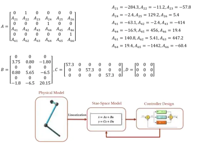
The linear model of the system has been calculated with the 'linmod' function by specifying input-outputs. It is a Matlab command that is used to convert non-linear systems to linear systems, which are explained by a large number of variables. In this study, linmod command is used to obtain the State-Space linear model of ordinary differential equation systems created by block schemes. In addition, the 'minreal' command is used to minimize unnecessary situations by neglecting uncontrollable or unobservable states of this model. The structure of the general State-Space model and the state vector [x], output vector [y], control vector [u] of the system are present in Eq.1. The state matrices [A, B, C, D] of the obtained model are given in Eq. 2 and Eq. 3.
𝑋̇ = 𝐴𝑥 + 𝐵𝑢 𝑦 = 𝐶𝑥 + 𝐷𝑢 𝑥𝑇 = [𝜃𝐻𝑝 𝜃̇𝐻𝑝 𝜃𝐻𝑟 𝜃̇𝐻𝑟 𝜃𝐾 𝜃̇𝐾] 𝑦𝑇= [𝜃𝐻𝑝 𝜃𝐻𝑟 𝜃𝐾] 𝑢𝑇= [𝜏 𝐻𝑝 𝜏𝐻𝑟 𝜏𝐾] (1)
𝐴 = [ 0 1 0 0 0 0 𝐴21 𝐴22 𝐴23 𝐴24 𝐴25 𝐴26 0 0 0 1 0 0 𝐴41 𝐴42 𝐴43 𝐴44 𝐴45 𝐴46 0 0 0 0 0 1 𝐴61 𝐴62 𝐴63 𝐴64 𝐴65 𝐴66] 𝐴21= −284.3, 𝐴22= −11.2, 𝐴23= −57.8 𝐴24= −2.4, 𝐴25= 129.2, 𝐴26= 5.4 𝐴41= −63.1, 𝐴42= −2.4, 𝐴43= −414 𝐴44= −16.9, 𝐴45= 456, 𝐴46= 19.4 𝐴61= 140.8, 𝐴62= 5.41, 𝐴63= 447.2 𝐴64= 19.4, 𝐴65= −1442, 𝐴66= −60.4 (2) 𝐵 = [ 0 0 0 3.75 0.80 −1.80 0 0 0 0.80 5.65 −6.5 0 0 0 −1.8 −6.5 20.15] , 𝐶 = [ 57.3 0 0 0 0 0 0 0 57.3 0 0 0 0 0 0 0 57.3 0 ] , 𝐷 = [ 0 0 0 0 0 0 0 0 0 ] (3)
Figure 3. The general process of linearizing the system and designing the controller
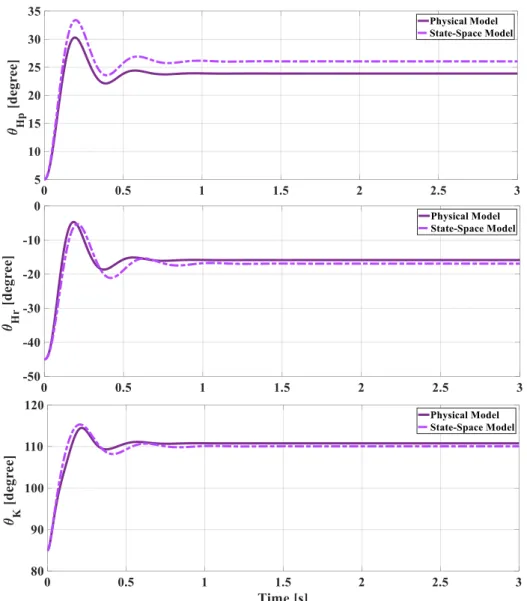
The general process of linearizing the system and designing the controller is shown in Figure 3. In order to compare the State-Space model of the system with the physical model, the system is simulated in 3 seconds. The constant torque values reference inputs are determined by considering the maximum angular position values required for the step foot trajectory. In Figure 4, uncontrolled angular position responses of joints of physical and State-Space models are given. Figure 5 shows the open-loop control block diagram of both models.
Figure 4. Open-loop control responses of the both models under unit step torque inputs
Figure 5. Open-loop control block diagram of Physical and State-Space models
As shown in Figure 4, both models showed a similar trend and at close value results. The maximum and average difference values between the angular position responses of the models are respectively; 3.2° and 2.1° for the Hip/pitch joint, 3.4° and 1.2° for the Hip/roll joint, 3.3° and 0.8° for the Knee joint.
THE PID and PIλDµ CONTROLLERS DESIGN
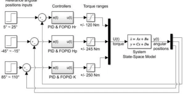
In this section, the fractional order Proportional-Integral-Derivative (FOPID) (Tepljakov,2019) controller and the classical PID are designed to comparative consider for the linear model of the robot leg are presented. PID controller is commonly preferred in experimental and simulation studies about single-leg of quadruped robots (Focchi et al., 2010). PIλDµ controller; in addition to the classical PID parameters, it is an advanced PID controller variant which includes the fractional derivative order (λ) and the fractional integral order (µ) parameters. It is stated that it is more flexible and durable because it has more adjustable design parameters. So, it can offer a wide controller response at higher performance (Podlubny et al., 1997; Podlubny, 1999). The block diagram of PID and PIλDµ controllers of system is given in Figure 6. The subsystem of controller blocks is shown in Figure 7.
Figure 6. The block diagram of PID and PIλDµ controllers of system
Figure 7. The subsystem of PID and PIλDµ controller blocks
And, the mathematical formula of classical PID controller and PIλDµ controller (externally includes fractional orders) are given in Eq. 4 and Eq. 5, respectively.
𝐶(𝑠) = 𝐾𝑝+ 𝐾𝑖 𝑠 + 𝐾𝑑 𝑠 𝑢(𝑡) = 𝐾𝑝𝑒(𝑡) + ∫ 𝑒(𝑡)𝑑(𝑡) 𝑡 0 + 𝐾𝑑 𝑑𝑒(𝑡) 𝑑𝑡 (4) 𝐶(𝑠) = 𝐾𝑝+ 𝐾𝑖 𝑠𝜆+ 𝐾𝑑 𝑠µ 𝑢(𝑡) = 𝐾𝑝𝑒(𝑡) + 𝐾𝑖𝐷−𝜆𝑒(𝑡) + 𝐾𝑑𝐷−µ𝑒(𝑡) (5)
SIMULATION RESULTS OF THE SYSTEM
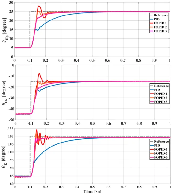
In this section, the PID and PIλDµ controllers for the linear model of leg are designed and simulated for 1 second. To investigate the effect of fraction orders (λ, µ) on the system, three different PIλDµ controllers are designed by various order values. The controllers’ responses to the angular positions of the three joints of the linear model obtained as a result of the simulation are given in Figure 8.
Figure 8. Control responses of the both models under unit step torque inputs
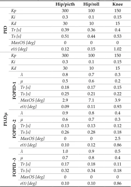
The designed parameters and the response specifications of controllers are presented in Table 2. The parameters of classical PID controllers are determined by basic Ziegler–Nichols methods (Ziegler and Nichols,1942) by also taking into consideration the previous studies (Bakırcıoglu et al, 2016a; Sen and
Kalyoncu, 2018). The parameters of the PIλDµ controllers are selected by trial and error methods based on experience and replaced by increased. In order to get more right comparison, the main gains of both controllers (Kp, Ki, Kd) are chosen the same. The simulations results are compared with regard to transient‐ response specifications such as Rise Time (Tr), Settling Time (Ts), Maximum Overshoot (maxOS), and Steady-State Error (e (t)).
Table 2. PID and PIλDµ controller parameters and response specifications Hip/picth Hip/roll Knee
P ID Kp 300 100 150 Ki 0.3 0.1 0.15 Kd 30 10 15 Tr [s] 0.39 0.36 0.4 Ts [s] 0.51 0.44 0.53 MaxOS [deg] 0 0 0 e(t) [deg] 0.12 0.15 1.02 P Iλ D µ Kp 300 100 150 Ki 0.3 0.1 0.15 Kd 30 10 15 F OPID -1 λ 0.8 0.7 0.3 µ 0.5 0.6 0.2 Tr [s] 0.18 0.17 0.15 Ts [s] 0.25 0.21 0.22 MaxOS [deg] 2.9 7.1 3.9 e(t) [deg] 0.09 0.11 0.93 F OPID -2 λ 0.9 0.8 0.4 µ 0.6 0.7 0.3 Tr [s] 0.13 0.13 0.12 Ts [s] 0.26 0.28 0.18 MaxOS [deg] 0 0 2.5 e(t) [deg] 0.10 0.12 0.86 F OPID -3 λ 1.0 0.9 0.5 µ 0.7 0.8 0.4 Tr [s] 0.17 0.18 0.11 Ts [s] 0.32 0.34 0.18 MaxOS [deg] 0 0 0 e(t) [deg] 0.10 0.10 0.86
As seen in Figure 8 and Table 2., the classical PID controller is insufficient in all response specifications. FOPID-1 ensure faster controller performance with less error despite a little overshoot. By increasing the value of fraction orders, FOPID-2 provided that time specifications and errors reduced, but there is still some overshoot in the knee joint. Finally, FOPID-3 ensured a faster and more effective than PID, but slightly less than other FOPIDs, controller performance with reasonable errors without overshoot. CONCLUSIONS
The physical model of the 3-DoF linear leg is designed, the linear state-space model is obtained by using linearization methods and the two type controllers are designed and the system is simulated. The unit step responses of the physical model and linear state-space model are obtained very close. In order
to examine the effects of PIλDµ controller's fractional derivative (λ) and integral (µ) orders, the same controller gains with PID controller are determined and the unit step responses of the system for both controllers are compared. In general, it is seen that the PIλDµ controllers, thanks to the fractional orders, are more superior to classical PID in terms of all response specifications although the same main gains are used. Furthermore, the performance of PIλDµ controller can be improved by tuning the parameters (particular fractional orders) using various optimization techniques.
REFERENCES
Bakırcıoglu, V., Sen, M.A. and Kalyoncu, M., 2016a, “Optimization of PID Controller Based on the Bees Algorithm for One Leg of a Quadruped Robot”, MATEC Web of Conferences, Vol. 42, No. 03004, pp. 1-4.
Bakırcıoglu, V., Sen, M.A. and Kalyoncu, M., “Adaptive Neural-Network Based Fuzzy Logic (ANFIS) Based Trajectory Controller Design for One Leg of a Quadruped Robot”, 5th International Mechatronics and Control Engineering (ICMCE 2016), Venice, Italy, 82-85, 14-17 December, 2016b. Bakırcıoğlu, V., Sen, M.A. and Kalyoncu, M., “Motıon Analysıs of The Robotıc Leg Mass Centre Durıng Reference Trajectory Trackıng” 2018 International Vocational Science Symposium (IVSS 2018), Antalya, Turkey, 420, 26-29 April, 2018.
Baudoin, Y. and Maki K. Habib, 2010, Using Robots in Hazardous Environments: Landmine Detection, De-Mining and Other Applications, Woodhead Publishing, Cambridge, London, England.
Boston Dynamics Company, https://www.bostondynamics.com/robots, access date: 12.09.2019.
Focchi, Michele, et al. “Control of A Hydraulically-Actuated Quadruped Robot Leg”, 2010 IEEE International Conference on Robotics and Automation (ICRA2010), IEEE, Alaska, United States, 4182-4188, 4-8 May, 2010.
Hutter, M., et al., “StarlETH: A Compliant Quadrupedal Robot for Fast, Efficient, and Versatile Locomotion”, International Conference on Climbing and Walking Robots (CLAWAR), Baltimore, USA 483-490, 23-26 July, 2012.
Hutter, M., et al., 2017, “Anymal-Toward Legged Robots for Harsh Environments”, Advanced Robotics, Vol. 31, No. 17, pp. 918-931.
Podlubny, I., 1999, “Fractional-Order Systems and PIλDµ Controllers”, IEEE Transactions on Automatic Control, Vol. 44, No. 1, pp. 208-214.
Podlubny, I., Dorcak L. and Kostial I., “On Fractional Derivatives, Fractional-Order Dynamic Systems and PIλDµ Controllers”, 36th IEEE Conference on Decision and Control, IEEE, Kobe, Japan, 1-5, 13-13 December, 1997.
Raibert, M., Blankespoor, K., Nelson, G. and Playter, R., “Bigdog, The Rough-Terrain Quadruped Robot”, In 17th World Congress the International Federation of Automatic Control, Seoul, South Korea, 10822-10825, 6-11 July, 2008.
Raibert, M.H., 1986, Legged Robots That Balance. MIT Press, Cambridge, London, England.
Rossell, J. M., et al. “Tracking Control for A Stewart Platform Prototype” 2015 International Conference on Advanced Mechatronics, Intelligent Manufacture, and Industrial Automation (ICAMIMIA), IEEE, Resort, Surabaya, 58-63, 15-16 October, 2015.
Semini, C., 2010, Hyq-Design and Development of a Hydraulically Actuated Quadruped Robot, Doctor of Philosophy (Ph.D.), University of Genoa, Italy.
Semini, C., et al., 2017, “Design of the Hydraulically-Actuated Torque-Controlled Quadruped Robot HyQ2Max”, IEEE/ASME Transactions on Mechatronics, Vol. 22, No. 2, pp. 635-646.
Sen, M.A. and Kalyoncu M., 2018, “Optimal Tuning of PID Controller Using Grey Wolf Optimizer Algorithm for Quadruped Robot”, Balkan Journal of Electrical and Computer Engineering, Vol. 6, No. 1, pp. 29-35.
Sen, M.A. and Kalyoncu M., 2019, “Grey Wolf Optimizer Based Tuning of a Hybrid LQR-PID Controller for Foot Trajectory Control of a Quadruped Robot”, Gazi University Journal of Science, Vol. 32, No. 2, pp. 674-684.
Sen, M.A. and Kalyoncu, M., 2015, “Optimisation of a PID Controller for an Inverted Pendulum Using the Bees Algorithm”, Applied Mechanics and Material, Section: Manufacturing Science and Technology VI, Chapter 7: Theory and Practice of Control, Vol. 789-790, pp. 1039-1044.
Sen, M.A., Bakircioglu V. and, Kalyoncu M., 2017b, “Inverse Kinematic Analysis of a Quadruped Robot” International Journal of Scientific & Technology Research, Vol. 6, No. 9, pp. 2277-8616.
Sen, M.A., Bakırcıoğlu, V. and Kalyoncu, M., “Design and Simulation Impedance Controller for Trajectory Control with Obstacle of Quadruped Robot’s Leg”, International Advanced Researches & Engineering (IAREC 2017), Osmaniye, Turkey, 558-568, 16-18 November, 2017a.
SimscapeUser’s Guide R2019b, The MathWorks Inc., 2012.,
https://www.mathworks.com/help/pdf_doc/simulink/sl_using.pdf, access date: 12.09.2019. Tepljakov A., FOMCON: Fractional-order Modeling and Control, http://www.fomcon.net, access date:
12.09.2019.
Velásquez-Lobo, Marlon Fernando, et al. “Modeling A Biped Robot on Matlab/Simmechanics” 23rd International Conference on Electronics, Communications and Computing (CONIELECOMP), IEEE, Cholula, Mexico, 203-206, 11-13 March, 2013.
Ziegler, J. G. and Nichols, N. B. “Optimum settings for automatic controllers”, Transactions of the ASME, Vol. 64, No. 11, pp. 759-765, 1942.