і *W4» * ч «.' » ♦ · · · «1 «/ ^ . Ц ^ ѣ 4(fc <4 •‘^ · ' - ^ U’ ^ V W ^ · Nî , * * . * i i .>?■· ; / -/С' ^· ’ Щ' w ♦ Ч- i Y г : ·^- - W w
. .'.ί·^.· ir ffO R ñ A t !0 Ñ T=C.'-I>;Oi,QGY COM?A^">'
y í íA
-S £ 4 > 8 . %
‘ A 4 7
AN IMPLEMENTATION OF STRUCTURED SYSTEMS ANALYSIS TO AN INFORMATION TECHNOLOGY COMPANY
A THESIS
Submitted to the Department of Management and the Graduate School of Business Administration
of Bilkent University
in Partial Fulfillment of the Requirements For the Degree of
Master of Business Administration By
Korhan Alparslan July, 1996
r i f
b S L i t . X ■
Ш
I certify that I have read this thesis and in my opinion it is fully adequate, in scope and in quality, as a thesis for the degree of Master of Business Administration.
n
o
0
Assistant Professor Serpil Sayın
I certify that I have read this thesis and in my opinion it is fully adequate, in scope and in quality, as a thesis for the degree of Master of Business Administration.
Assistant Professor Dilek Önkal
I certify that I have read this thesis and in my opinion it is fully adequate, in scope and in quality, as a thesis for the degree of Master of Business Administration.
/
^
Assistant Professor Can ^in jg a Mucjan
Approved by the Dean of the Graduate School of Business Administration
€
ABSTRACT
AN IMPLEMENTATION OF STRUCTURED SYSTEMS ANALYSIS TO AN INFORMATION TECHNOLOGY COMPANY
BY
KORHAN ALPARSLAN M.B.A. THESIS
BILKENT UNIVERSITY - ANKARA JULY, 1996
Supervisor: Dr. Serpil SAYIN
Systems Analysis is the process of analyzing an organization with the ultimate objective of modifying and improving it. It is a way of solving problems existing in organizations. Structured Analysis, with the aid of visual capabilities, is the most commonly applied technique of implementing systems analysis. The two major components of structured analysis are Data Flow Diagrams(DFDs) and Data Dictionary. W ide-spread usage of Computer-Aided Software Engineering(CASE) tools that support systems analysis and design made the structured analysis process easier to manage and control.
This study aims to apply structured analysis methodology to a Turkish company that operates in the information technology industry. Context diagram which is level 0 DFD is developed initially. Then the level 1 and level 2 DFDs are produced. The DFDs display the processes of each department and data flow between, in and out of departments. Each process that exists in the level 2 DFDs is explained and the data dictionary is provided in the appendices. The study concludes with a summary of recommendations that can be implemented for the improvement of the organization work flow.
Keywords: Systems Analysis, Structured Analysis, Data Flow Diagrams, CASE, Structured Analysis Implementation
ÖZET
YAPISAL SİSTEM ÇÖZÜMLEME YÖNTEMİNİN BİR BİLGİ TEKNOLOJİSİ ŞİRKETİNE UYGULANMASI
HAZIRLAYAN KORHAN ALPARSLAN İŞLETME YÜKSEK LİSANS TEZİ BİLKENT ÜNİVERSİTESİ - ANKARA
TEMMÜZ, 1996
Tez Yöneticisi: Dr. Serpil SAYIN
Sistem Çözümleme bir organizasyonun iyileştirilmesi ve geliştirilmesi hedefini güden işlemdir. Organizasyonlarda bulunan problemleri bir çeşit çözme yöntemidir. Yapısal Çözümleme ise, görsel özelliklerinin yardımıyla, en çok başvurulan sistem çözümleme uygulama tekniğidir. Yapısal Çözümlemenin iki temel bileşeni veri akış çizgeleri(VAÇ) ve veri sözlüğüdür. Sistem çözüm leme ve tasarımını destekleyen bilgasayar destekli yazılım mühendisliği (BDYM) araçlarının yaygın kullanılmaya başlanmasıyla yapısal çözümleme işlemini yönetm ek ve kontrol etmek daha kolaylaşmıştır.
Bu çalışmanın amacı, yapısal sistem çözüm leme metodolojisinin bilgi teknolojisi endüstrisinde faaliyet gösteren bir Türk şirketine uygulanmasıdır. İlk olarak 0 düzeyi VAÇ olan bağlam şeması oluşturulmuştur. Sonra, daha detaylı birinci ve ikinci düzey VAÇlar üretilmiştir. VAÇlar her departmanda bulunan işlemleri ve departm anlar ile işlemler arası veri akışını gösterir. İkinci düzey VAÇlarda bulunan her işlem anlatılmış ve veri sözlüğü ekte sağlanmıştır. Çalışma organizasyon iş akışını geliştirebilecek tavsiyelerin bir özetiyle sonlanmaktadır.
Anahtar Kelimeler: Sistem Çözümleme, Yapısal Çözümleme, Veri Akış Çizgeleri, BDYM, Yapısal Çözümleme Uygulaması
Acknowledgements
I would like to thank to the managers and employees o f Datakom Corporation that supported and helped me in achieving my study. Also, I am grateful to my thesis supervisor Dr. Serpil Sayın for her helpful critism and assistance in developing this thesis.
TABLE OF CONTENTS
ABSTRACT... OZET... ACKNOWLEDGMENTS...
1. INTRODUCTION... 1
2. INFORMATION ABOUT THE COMPANY... 4
2.1 Company Profile... 4
2.2 Organization... 6
3. LITERATURE SURVEY... 7
3.1 System Analysis Methods...7
3.1.1 What is Systems Analysis... 7
3.1.2 Common Systems Analysis Methodologies... 7
3.2 A Brief History of Structured Analysis... 11
3.3 Basic Notations of Structured Analysis... 12
3.3.1 Data Flow Diagrams... 13
3.3.2 Data Dictionary... 14
3.3.3 Data Structure Diagrams... 15
3.3.4 Data Access Diagrams... 15
3.4 Why Structured Analysis?... 15
4. DATA GATHERING AND SELECTED SOFTWARE... 17
4.1 Data Gathering... 17
4.2 CASE Tools... 17
4.3 Taxanomy of Case Tools... 18
4.4 Information About the Selected Software... 18
5. STRUCTURED SYSTEMS ANALYSIS IMPLEMENTATION...21
5.1 Datakom Context Diagram...21
5.2 Information Services and Sales Operations... 26
5.2.1 Trade Department...26
5.2.2 Sales and Marketing Department... 26
5.2.3 Hardware Support Department... 27
5.2.4 Software Support Department... 27
5.2.5 Finance Department...27
5.2.6 Accounting and Personnel Department... 28
5.3 The Processes of Trade Department... 30
5.3.1 Order Evaluation;... 30
5.3.2 Bank Application:... 30
5.3.3 Transportation Follow-up:...30
5.3.4 Document Follow-up...31
5.3.5 Delivery Operations...32
5.3.6 Closing Bank Engagements:... 32
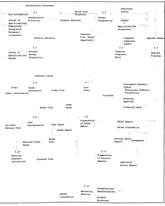
5.4 The Processes of Sales Department... 35
5.4.1 Adjudication Follow-up...35
5.4.2 Tender Preparation...35
5.4.3 Project Tender Preparation... 36
5.4.4 Computer Component Sales... 37
5.4.5 Upgrade Proposal...37
5.4.6 Order Acceptance...37
5.4.7 Give O rder... 38
5.4.8 Cost Determination...38
5.4.9 Preparation of Sales Report... 39
5.4.10 Retailer Discount Calculation...39
5.4.11 Preparation of Routine Reports... 39
5.4.12 Marketing Efforts...40
5.5 The Processes of Hardware Support Department... 42
5.5.1 Product Exit... 42
5.5.2 Preparing the System...42
5.5.3 Warehouse Entrance...43
5.5.4 Call Evaluation...43
5.5.5 Problem Solving...43
5.5.6 Preparation of Maintenance Calendar... 44
5.5.7 Periodic Maintenance...44
5.5.8 Preparation of Maintenance Contract... 44
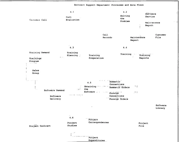
5.6 The Process of Software Support Department... 46
5.6.1 Call Evaluation...46
5.6.2 Solving the Problem...46
5.6.3 Training Planning...46
5.6.4 Training Services...47
5.6.5 Obtaining Software...47
5.6.6 Project Studies...47
5.7 The Processes of Finance Department... 49
5.7.1 Preparing Payments & Dues Plan... 49
5.7.2 Payment Preparation... 49
5.7.3 Bank Sheet Preparation... 49
5.7.4 Annual Budget Preparation... 50
5.7.5 Monthly Expense Calculations... 50
5.8.1 Invoice & Waybill Preparation... 52
5.8.2 Expense Evaluation... 52
5.8.3 Advance Payment... ' 52
5.8.4 Invoice Payment... 53
5.8.5 Accounting Slip Preparation... .. 5.8.6 Accounting Reports Preparation... 53
5.8.7 Personnel Follow-up... 54
5.8.8 Social Security Lists Preparation... 54
5.8.9 Salary List Preparation... 54
6. CONCLUSION... gg 6.1 Main Problems Observed and Recommendations... 6.2 Last W ord... gg Appendix A: Trade Department Data Dictionary Entries...60
Appendix B: Sales and Marketing Department Data Dictionary Entries 61 Appendix C: Hardware Support Department Data Dictionary Entries... 63
Appendix D: Finance Department Data Dictionary Entries...65 Appendix E: Accounting and Personnel Department Data Dictionary Entries 66 BIBLIOGRAPHY... gg
LIST OF ILLUSTRATIONS
Figure 3-1 Relationship among four types of models of Structured Analysis... 8
Figure 3-2 Systems Development Life Cycle (the waterfall model)...9
Figure 3-3 Information Flow M odel... 12
Figure 3-4 Yourdon DeMarco Data Flow Diagram...13
Figure 4-1 “EasyCase for Windows” Interface Sample...20
Figure 5-1: Datakom Context Diagram... 25
Figure 5-2: Information Services and Sales System...29
Figure 5-3: Trade Department Data Flow Diagram...34
Figure 5-4: Sales Department Data Flow Diagram... .. Figure 5-5: Hardware Support Department Data Flow Diagram... 45
Figure 5-6: Software Support Department Data Flow Diagram...48
Figure 5-7: Finance Department Data Flow Diagram... Figure 5-8: Accounting Department Data Flow Diagram... 55
1. INTRODUCTION
A system can be defined as a network of interrelated procedures that are joined together to perform an activity or to accomplish a specific objective (Kendall,1987). The procedures that are connected with each other form a whole which is the system itself. A procedure is a precise series of instructions. It helps to specify by whom, when, and how something has to be done.
Systems are classified as open and closed systems. Simply, a closed system controls or modifies its own operations by responding to data generated by itself. An open system, unlike a closed system, requires external control. That is, such systems get input from the environment in generating its output.
Systems analysis is simply a way of problem solving. Organizations are systems and it is the systems analysts' task to solve the problems orienting from the structure and culture of the organization. Systems analysis study is the requirements gathering, analysis, and definition stage. During this stage, the analyst who accomplishes the systems analysis study, recommends what the system is expected to do, and specifies the functional requirements. It resembles the "blueprint" stage of a construction study.
There are many systems analysis methodologies. Some of them support structured systems development techniques, some of them are unstructured. The availability of CASE (Computer Aided Software Engineering) tools starting with the common usage of computers increased the interest in structured methodologies. In this thesis, a systems analysis study is implemented with the support of a CASE tool.
With the beginning of fifties, the era of manufacturing started to decline. The percentage of labor force in the industry decreased day by day in the developed countries. Later, the labor force was directed to the service organizations. Today the trend is information. The domination of capital is currently replaced by information. The major tools of information- society is computers, data communication, electronic networking, and brain power.
It is commonly accepted that, the strategic resource in an information oriented society is knowledge. Knowledge of systems analysis and design is more important today than ever, as
computer networks are transforming the world into a global office. Internet is a good example to this fact. The capabilities of Internet allow us to make contact with other companies, governments, and other government institutions. To be competitive with others, all firms have to provide information to themselves using the features of computers.
Data that is not processed is worthless. Several tools help us in converting raw data into knowledge. Software is the most important of these tools. The effective usage of computers is only available with the suitable software. The first step in developing this software or the management information system is the systems analysis study. Therefore the systems analysis study will have great importance in the near future especially in Turkey, because most companies do not possess an integrated information system.
Computer networks make the company data available throughout the world. But properties like accuracy, availability, correctness of the information do not exist all the time. Integration in a company is essential in order to provide those properties of information. The departments of most companies work separately. This may cause data repetitions, and inconsistency. Data required for a department may not be available in time. These are the possible outcomes of working without an information system. The usage of management information systems is the key in preventing such problems. The systems analysis study is the starting point in achieving an effective information system.
Systems analysis is not a simple task to implement. Orr had stated, "Systems building is an art, and it is unlikely that this situation will change very much until we develop new methods for training systems designers and architects in the building of complex systems" (1977). Only systems analysis methodology knowledge is not enough for achieving a successful analysis. It requires the knowledge of computers, programming, basic business functions, data communications, and database concepts which are related with computer science, accounting - finance principles, and marketing related with business administration, and other subjects depending on the specific area that the systems analyst works in. Also, it is suggested to have a considerable work experience in the related area. So it is the systems analyst's responsibility to understand the functioning of an organization.
In the thesis a systems analysis study is offered for the Datakom Corporation. In the second chapter, information about the company is presented. The third chapter briefly defines
systems analysis and examines the structured systems analysis method. The fourth chapter describes the data gathering methods, CASE tools, and selected software for the study.-The systems analysis study for Datakom is presented in the fifth chapter. Finally the study is concluded with a summary of recommendations that can be done in the design and implementation stages.
2. Information About the Company
2.1 Company Profile
The company is the Turkey distributor of some foreign information technology equipment manufacturers. Computer systems, hardware, and computer peripheral units are not the only product types sold. In addition software programs, technical and educational services are provided to customers.
The company, which has been founded in early seventies, has become one of the largest computer service companies in Ankara. In the early years of its life, it served special engineering projects like development of custom tailored management information systems for certain companies, geographic information systems implementations, full computer hardware and software solutions. Most of these huge studies were accomplished during the 1970s and early 1980s where there were few competitors in the sector.
Before the beginning of 1980, the company initiated an organization restructuring process. The increasing work load had made such a change necessary. It was decided to organize software production and hardware sales as different groups. The consequence of that change increased the control and coordination throughout the company because management of both groups began to deal with the projects regarding itself. The company divided into two divisions; one specializing in engineering projects such as software developments, and construction projects, the other began to deal with original equipment manufacturer(OEM) products sales, marketing, and support. Both divisions worked like separate companies until the year of 1993.
As new firms entered the computer industry the competition increased. In the past, there were relatively few firms in the market and the firm enjoyed high profit margins. But intense competition beginning with 1990s caused significant reductions in profits. Finally high losses in 1993 made some strategic changes necessary. In that year, the management of both software and hardware divisions were united forming a unique organization. This change also made some positions unnecessary. The personnel decrease caused reductions in overall costs, but this was not good enough.
The software industry in Turkey was occupied by many small software houses. Those firms produced programs that are usable by many clients. The profit margins decreased in specialized software developments because of the economies of scale in new products. With the economic crisis in 1994, the company went to a second employment contraction by dissolving finished project groups.
The company is continuing its activities as the representative of a few peripheral unit manufacturers and a US based computer manufacturer. The sales and marketing activities are taken for those companies' products. But the bulk of sales come from computer sales; mainframes, mini, micro computers and other auxiliary devices of this brand. The engineering activities declined as a result of personnel contraction and the company focused itself on sales.
Although it is a sales oriented organization, most of the profits come from services. After selling the products to customers with a low profit margin, annual maintenance agreements are signed. The major source of income is the maintenance agreements giving great emphasis to old customers.
The customer portfolio includes mainly state organizations, universities and state economic establishments. There are also a couple of privately owned companies which have purchased company products. It is visible that most of the current customers are owned by the state. Sales done to state organizations usually end up in a low rate of profit because of heavy competition and bidding. The profit of the company then comes from after sales services provided to those customers. The services include solving technical problems originating either from software or hardware, special trainings that are offered upon demand and periodic maintenance of the systems.
As the competition in market increased, achieving new sales became harder each day. For sustaining profit continuity the company started to be more service oriented. The ratio of income generated from services is in an increasing trend in the recent years. To keep this trend continue, service quality must be increased also. For improving service quality, the company management has initiated an information system development project which is based on the systems analysis study completed in this thesis. A positive change in service
quickly provides an enhanced ability to compete and gain a competitive advantage in the long- run.
2.2
Organization
The company is organized as technical support, sales and marketing, finance and accounting, and trade departments.
The technical support consists of two separate divisions: Software support and hardware support. Software support deals with the problems arising from system software. System software includes the operating system, compilers, communication programs, and other system programs that have been sold with the computers. Hardware support has two functions. The first is to solve hardware problems of customers. The second is to perform periodic maintenance. Periodic maintenance is done according to service agreement contracts signed with the customers. If the customer does not have service contract, periodic maintenance is not given. In case of a failure, the customer calls the support department for serving to him.
Sales and marketing department prepares proposals to firms according to demands. Preparing a proposal to public and private establishments are quite different in style. The public proposals have to fulfill each of the written technical requirements and have to be in a predefined style.
Trade department is mostly busy with follow-ups of imports. When an order is passed to a foreign supplier, it takes long way to transport it to the customs office and taking it out of the customs office.
Finance department is responsible for finding the funds necessary for the company operations and controlling the cash flow.
Accounting department keeps compulsory accounting books and provides a basis for the reports preperation of finance department.
3. LITERATURE SURVEY
3.1 Systems Analysis Methods
3.1.1 What is Systems Analysis
Systems analysis is the process of analyzing a system with the potential goal of improving and modifying it (Fitzgerald 1987). In other words systems analysis involves the study and design of something in order to modify it.
If the term "systems analysis" is studied as separate words, analysis is the process of breaking down problems into smaller elements for study and, ultimately, finding a solution(Fitzgerald,1987). System is a set of interrelated and interacting component parts that, when put together, function to achieve a predetermined goal or objective.
The systems analysis approach to a problem differs from a trial and error approach. The trial and error approach involves identifying a number of potential solutions to the problem and then testing each until an acceptable solution is found. In the systems analysis approach, all major influences and constraints are identified and evaluated in terms of their impact on the various decision points in the system. A decision point is that point in a system at which some person or automatic mechanism reacts to make a decision (Orr 1977).
3.1.2 Common Systems Analysis Methodologies
The basic tools of systems analysis are various types of diagrams used to model an organization as an information system, the most important being the data flow diagram. The data flow diagram(DFD) portrays the system in terms of its component pieces. The flow of data between sources, sinks, processes and data stores are described by DFDs.
According to structured analysis, four step modeling should be implemented. (Fitzgerald 1987). These are the modeling of current physical, the current logical, the new logical, and the new physical system respectively (Figure 3-1). Each step should consist of a complete description of the system by DFDs, the data dictionary and mini-specifications.
Figure 3-1 Relationship among four types of models of Structured Analysis
Source: Fitzgerald, 1987
Other than structured analysis and design, the analysis study can be implemented by a hierarchical approach. In general, it is to break down a big problem into successively smaller parts, until it is not possible to subdivide. In hierarchical analysis, the analyst asks, "how can this job be broken into a series of simpler ones?". The HlPO (Hierarchical-Input-Process- Output) methodology utilizes the hierarchical analysis in detail.
The analysis of a problem into parts is a useful process, and it is most effective if the same procedure is applied to each part of the problem. In a complete analysis this process continues until each of the pieces is so simple that there is no need to break them down further.
There are a number of drawbacks of hierarchical analysis. One is that it seems to create a lot of work, especially at the lower levels. Further, it requires that you have some idea of the top of the system and the major parts at each step. Finally hierarchical analysis poses the question: How can the system at the first place to be broken into pieces can be determined? According to Zwass (1992), there are two major development methods, which are Systems Development Life Cycle (SDLC) and Systems Development through Prototyping.
Systems Development Life Cycle (SDLC):
This method has become a traditional method. It relies on a formally defined sequence of stages in the process of developing and maintaining an information system. Each stage has
its own outputs and documentation. This resource-intensive process produces highly maintainable systems. It is particularly advantageous when applied to large systems; such as those used for transaction processing.
The major stages of SDLC are systems analysis, systems design, programming and maintenance. These stages include sub-stages and at the end of each stage, either the next step studies starts or previous stage is reworked if required. This approach in SDLS has been named as waterfall model in the early 1970s. (Figure 3-2).
Tasks Development Stages Deliverables
F e a s ib ility S tu d y ^ R e c o m m e n d a tio n to p ro c e e d or re c o m m e n d a tio n to ab a n d on S y s te m s ' A n a ly s is 1 1 ' 1 . ^ . 1 R e q u ire m e n ts
A n a ly s is -j;:: R e q u ire m e n ts spe c ific a tio n s
• ■ ' i " ‘ U L o g ica l D e s ig n jijij C o n c e p tu a l d es ig n o f p ro g ra m s a n d d a ta b a s e s S y s te m s 1 ■ : ... D e s ig n ' p - ... 1 1 i;| • P h y s ic a l D e s ig n w D e ta ile d d e s ig n o f m o d u le s an d d a ta b a s e s
P ro g ra m m in g ... - ' C o d in g & T e s tin g iiii;...- --· A c c e p te d S y s te m with c o m p le te d o c u m e n ta tio n
In s ta lla tion 1 C o n v e r s io n ii·:: - ... 1 In s ta lle d O p e ra tio n a l S y s te m
P o s t
M a in te n a n c e ' Im p le m e n ta tio n ; R e c o m m e n d a tio n for e n h a n c e m e n t A udit
igure 3-2 Systems Development Life Cycle (the waterfall model)
Source: Zwass, 1992
In the late 1970s, structured SDLC began to emerge. It used tools to handle the complexity of information systems development. Both systems analysis and design moved from abstract level to more detailed level with the support of techniques such as DFDs, structure charts, and data dictionary.
Systems Development Through Prototyping:
In this method, an early pilot version of the system is built, so that the future users can clarify their requirements and gain a measure of confidence in the general approach. Contrary to SDLC, there is no distinct steps for the development of the information system. A trivial software is developed, and the final system is composed of considering the complaints and advice of end users. So, there is almost no systems analysis study accomplished when this approach is employed.
Recent studies have showed that structured system development methodologies is now frequently used in systems development. In a survey of ninety-seven organizations (Necco, 1987), it was found that 69 percent used SDLC based on traditional tools (such as narratives and flowcharts) on some of their projects, and 62 percent used structured SDLC. Twice as many of the firms were considering using structured SDLC in the future. SDLC is employed by most of the firms and a significant portion of these firms are at least expecting to use structured SDLC in the future. This is a concrete evidence that structured analysis and as a result of it, structured SDLC will be the major systems development and analysis approach. Today, in real life some systems analysts relied on personal interviews and judgment rather than applying approaches developed by theorists(Yourdon, 1989). The basis of such system developments are to do personal interviews with the key persons, conduct questionneries and to develop a narrative systems analysis study. The logical and physical systems are formed in this way and the suggested system is developed in the light of this documentation. This system, alone itself, is used rarely in real life, because it has difficulties in explaining the flow of information throughout the organization. The lack of drawings and charts is one of the reasons that make this style hard to implement.
Instead of implementing a unique method to an organization, more than one can be used. Most frequently hybrid approaches are applied. For example an analyst may start with structured analysis and support the analysis with personal interviews. This is sometimes due to the cost and time constraints of the analysis study, and sometimes the size and complexity of the organization that is analyzed is the determinant.
3.2 A Brief History of Structured Analysis
Structured analysis, like all software requiretrients analysis methods, is a model building activity. Structured analysis is not a single method applied consistently by all who use it. Rather, it is a mixture that has evolved over almost twenty years.
In his book on the subject, Tom DeMarco (DeMarco 1979) after understanding the failings of the analysis phase has determined the goals to be accomplished in this stage. The first goal is that, the products of analysis must be maintainable. This applies particularly to the target document. The second goal is, to deal with big and complex problems using an effective method of partitioning. The third goal suggests the use of graphical interface whenever possible, and finally the logical(essential) and physical(implementation) characteristics have to be differentiated.
After determining those goals of systems analysis, he has concluded with the requirements to accomplish these goals. These requirements are, a tool to help the designers partition the requirements and document that partitioning before specification, some means of keeping track of and evaluating interfaces, and new tools that describes the logic better than plain text. Like many important contributions to software engineering, structured analysis was not introduced with a single landmark paper or book that was a definite treatment of the subject. Early work of analysis modeling was begun in the late sixties and early seventies, but the first appearance of the structured analysis approach was an addition to another important topic, "structured design."
Researchers needed a graphical notation for representing data and processes that transformed it. These processes would be mapped into a design architecture.
The term "structured analysis" became popular by DeMarco's methodologies. DeMarco introduced and named the key graphical symbols that would enable an analyst to create an information flow model. Data dictionary and processing narratives were introduced by him as a supplement to graphical notations. In the recent years that followed, variations of the structured analysis approach were suggested by Page-Jones, Gane and Sarson, and many others (Evergreen, 1994).
By the mid 1980s, the deficiencies of structured analysis became painfully apparent. These were mostly due to the lack of providing an adequate notation for real-time engineering problems. Real-time extensions were introduced by Word and Mellor and later by Hatley and Pirbhai (Pressman, 1992). These extensions resulted in a more robust analysis method that could be applied effectively to engineering problems. Today, attempts to develop one consistent notation have been suggested.
3.3 Basic Notations of Structured Analysis
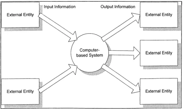
structured Analysis is an information flow model and content modeling technique. A computer based system is represented as an information transform as shown in Figure 3-3 (Pressman, 1992). The overall function of the system is represented as a single information transform, noted as a bubble in the figure. One or more inputs originate from external entities. The input is processed in the bubble and output information passes to external entities. This model should be applied to the entire system and the software element only. The key is to represent the information fed into and produced by the transform.
Figure 3-3 Information Flow Model
Source: Pressman 1992
3.3.1 Data Flow Diagrams
The data flow diagram(DFD) is a graphical technique that shows information flow and the transformations that are applied as data move from input to output. The information flow model that is illustrated in Figure 3-3 is a basic data flow diagram.
Data flow diagram maybe sued to represent a system or a software at any level of abstraction. In fact, DFDs may be partitioned into levels that represent increasing information flow and functional detail. A level 0 DFD is also called a context diagram. It represents the whole software element as a single bubble with input and output data. Level 0 DFD for an organization exhibits the main function of the organization with a bubble and its relations with external environment in the form of physical input and outputs.
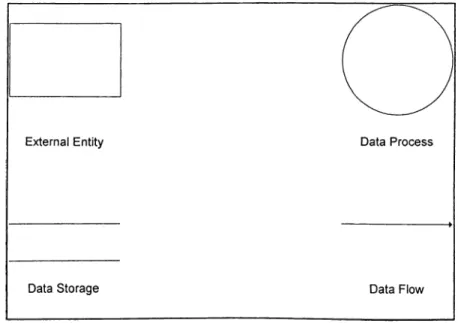
Figure 3-4 Yourdon DeMarco Data Flow Diagram
Data flow diagrams are constructed using the symbols shown in Figure 3-4. These symbols are according to the terminology of Yourdon and DeMarco. An external entity is the receiver or sender of data or information. It is any kind of entity that the organization interacts with. They may be customers, suppliers, government institutions, and so on.
A process is depicted by a circle. Processes show the transportation of the content or status of data. In other words, some sort of data processing takes place in a circle. Each process has at least one data inflow and outflow. The numbers identifying processes are unique. The number to the left of the point indicates the level (depth) of the process. Level 0 is always the
context diagram and it includes only one data process which is the main function of the organization. Other levels have more than one process circle starting with a number indicating the level of the diagram.
A data store symbol represents any kind of source in which data resides. In a manual system it can be forms, paper reports, card files, or in a computerized system it may be tapes, disks, or databases.
The fourth symbol is the data flow symbol. This symbol is used to show the flow or movement of data between process bubbles, external entities, or data stores. One end of the data flow must be connected to a process. The flows can be physical like, letters, reports, vouchers, receipts or can be in any form like telephone calls.
3.3.2 Data Dictionary
A data dictionary is a documentation that supports data flow diagrams. It contains all the terms and their definitions for data flows that relate to a specific system. The purpose of the data dictionary is to define the contents of the data flows and data stores, with the exception of processes that are defined separately. Data dictionary provides consistency. It prevents calling different data flows with same name, and same flows with different names.
Yourdon (1989) defines data dictionary as an organized listing of all data elements that are pertinent to the system, with precise definitions so that both user and analyst have a common understanding of inputs, outputs, components of stores and intermediate calculations.
The data dictionary includes the data structures defining data flows and data stores. The combinations of data elements in a data store form a data structure. Meaningful combinations of data elements are called data structures. For example, the fields on an application form compose a data structure for that particular form.
3.3.3 Data Structure Diagrams
The data structures must be organized for use. To do this, the data structures are organized into a model that shows the business objects and their relationships for all stored data in the
system. This modeling of data structure relationship is called as data structure diagrams. They are graphic means of showing access relationships between data structures.
3.3.4 Data Access Diagrams
A data access diagram is used to picture the more detailed representation of each data structure, the corresponding relationships between data structures, and the access paths between them. The purpose of data access diagram is to show the formats of the data structures and the corresponding relationships for the system. Throughout this process the primary concern is the data; how it flows, how part of it is shown that is related to others.
3.4 Why Structured Analysis?
In the article by Bansler, and Bodker (1993), three large Danish organizations have been analyzed (A bank, utility company, and a financial institution) that have implemented systems analysis. They have concluded their study with the following findings:
• None of the organizations have chosen structured analysis out of a variety of available methods for systems analysis. Structured analysis has been perceived as the only feasible method for systems analysis in a large business environment.
• The reason underlying the selection of structured analysis has been the knowledge by designers on the subject.
• The designers have not made four different models that represent the current physical, current logical, new physical and new logical models. Even they have not distinguished between logical and physical data flow diagrams.
There is not any accepted style of the structured analysis by the designers. In all three companies different features and models of the method are used. The parts chosen not only differ from company to company but even from project to project. As a result, it can be said that the structured analysis methodology is not known by designers in detail, but it is accepted as the most correct tool for systems analysis. The findings of Necco(1987) also support this argument as more firms are considering to use structured analysis in their systems development projects.
Yourdon has recommended in his study, the use of structured techniques in projects ranging from ten thousand to one million lines of code (Yourdon 1982). This finding would have been appropriate in the past but today programming techniques have changed dramatically. A subprogram may accomplish the features of a thousand lines of code of a past COBOL program. The inheritance property of object oriented programming\ use of libraries^, and 4GLs^ allow programmers to write very short programs but do lots of work. So, today Yourdon’s finding is no longer a valid criterion for applying structured analysis. It is agreeable to implement structured analysis in large and complex projects but the criteria for this complex and simple, large and small is not so certain.
In conclusion, in practice what happens is that experienced designers - instead of following rules and procedures of structured analysis - pick and choose among the various formalisms given in the method, and adapt them for their own purposes (Bansler and Bodker 1993).
^ Object Oriented Programming: A modern programming technique which uses objects rather than classical variable property of programming languages.
^ Programming Library: A compiled group of procedures coded for a specific purpose which can be reusable with many programs.
^ Fourth Generation Languages: A new generation of programming language which suggests the programmer to tell “what to do" rather than “how to do it."
4. DATA GATHERING AND SELECTED SOFTWARE
4.1 Data Gathering
There was no written document about the functioning of the company under study. Therefore the necessary information is collected by individual interviews. The interviewees were the company personnel who directly deal with processing in the system. Company management, department managers, sales representatives, product managers, support engineers, and finance and accounting personnel were among the employees interviewed.
During the interviews, the system functioning and the extraordinary situations are found out. The written documents used throughout the company were collected and added to the data flow diagrams as data storage. These documents are an important part of the data flow throughout the company, and therefore, they are added to the appendix in the form of data dictionary entries.(See Appendixes A-E)
4.2 CASE Tools
CASE is an acronym for Computer Aided Software Engineering. CASE is a relatively new technology. The need for automating the structured analysis, design, and data modeling methods caused the CASE technology to improve in the recent years.
The first product was introduced for usage in 1981 by STRADIS/DRAW^. The first tools carried only graphics capabilities that helped the analysts in diagrams. Soon after, new products were released with consistency and completeness testing facilities. The first product in that category was EXCELERATOR (1984). The success of it really established the market for CASE tools. In the recent years, the widespread use of relatively low cost, powerful computer systems increased the demand for such tools.
There are many CASE tools available to cover one or more stages of the system development life cycle including analysis, design, coding, and testing. The sophistication of the tools arises as the stages covered by a CASE tool increase. It is important to note that a CASE tool is not
' The first case tool developed by Stradis Corporation.
a magical solution provider to system development. To use a CASE tool effectively, one must have an understanding of structured development methods.
The data dictionary is one of the features that makes a CASE tool so powerful. It is a collection of information about each object used on the charts in a project. Each unique object has a matching record in the data dictionary.
It is expected that CASE will do for computer software development what CAD (Computer Aided Design) has done for hardware development, that is, to enable the rapid, accurate, cost effective development of system software.
4.3 Taxanomy of Case Tools
CASE tools can be used at a variety of places regarding systems development. Here, some of their usages by function are discussed briefly (QED 1989).
They can be used as a business systems planning tool. The objective of this tool is to help understanding of information flow between organizational units.
There are CASE tools that focus on project management. But today, project management software have made them obsolete.
CASE software as support tools encompasses the activities of entire software engineering process such as quality assurance of programs, networking tools, documentation tools. Some CASE tools support analysis and design like the one used in this study. The tool contains data and control flow, data content, process representations and other modeling representations. They assist in the creation and evaluation of the model by performing validity and consistency checks.
The programming tools provide the compiler, editor, debugger functions to the programmer. The final group of CASE software encompass testing and maintenance tools.
4.4 Information About the Selected Software
The EasyCASE Systems Designer® program and documentation introduce the concepts of structured analysis, design, data modeling methods, and CASE. These concepts should in
Developed by Evergreen Case Tools, Inc.
turn help the basic knowledge of the methods and techniques required to implement full CASE solution.
EasyCASE works on personal computers under Microsoft Windows operating environment. Its graphical user interface enables a user-friendly environment. First, the user starts a new project. All written and visual materials are stored under that project directory. The main approach of the program is to form charts using the desired type and methodology. The charts are drawn usually hierarchically. This means that charts go from simple to detail. A data dictionary entry is created for every object in the charts.
The program supports several diagram types in order to implement structured analysis, design, and data modeling concepts. The diagram types are;
• Data flow diagrams (DFD) • Data model diagrams (DMD) • Data structure diagrams (DSD) • Entity-relationship diagrams (ERD) • Structure Charts (STC)
• State-transition diagrams (STD)
EasyCase produces these charts according to some methodologies and symbologies. The important ones of these methodologies are Yourdon/DeMarco, Gane & Sarson, SSADM, Jackson, Shlaer & Mellor, Chen, Martin, and IDEF1X.
There are four basic types of objects that can be used on charts:
• Symbols: A symbol represents an object on a chart. Symbols include such objects as data processes on data flow diagrams, control transforms on transformation graphs, module on structure charts, entities on entity relationship diagrams, and states on state transition diagrams.
• Connections: A link between two symbols on a chart that indicates the flow of information or resources, or the relationship between the two symbols.
• Interfaces: A connection that joins a process on one chart with an off chart entity. It is a special type of connection.
• Couples: Annotate a connection on a structure chart with data or control information passed by a call between functions or modules.
» E a s y C A S E System Designer - [Sales Order Processing]
File Edit Objects View Options Explode Schema Tools Vflndow ^
DJEISIII 0 0 0 1 1
Bl
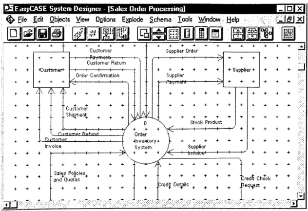
■r A' '■ + CU2tonrif;r -Paymerit«· Customer Return I -Order Corifirmstion • 4 + 4 + + _ 4. 4 . 4. *. 4-Uustomer Ship,m snt^ ^ ^ ^ — Citstnmer Refiinrl. Invoice 4 + 4 upplier Order + 4 + Supplier f + 4 + 4 + t + t i^took Ppi'duct H--- 1---- \---+ ·^nvertíon/■^ S y s te rri / V^ 4 . 4 4- + 4- 4 . Supplier + + 4 + 4^· f + 4 + , + + ^ .D r e d J D e ta ils ^ ^ ^ ^ ^ ^Figure 4-1 “EasyCase for Windows” Interface Sample
As structured analysis was intended to be used as a graphical descriptive technique, it requires a lot of paperwork. It was recognized that to avoid the huge paperwork of structured analysis CASE tools were the best alternative.
In this study, the DFDs with Yourdon/DeMarco method were used in developing systems analysis study. The documentation of DFD processes, data flows, and data storages were done with a text file link (that is a feature of the program) connected one to each data process symbol. After completing the study, the process explanations and data dictionary items were converted into Microsoft Word document.
5. STRUCTURED SYSTEMS ANALYSIS IMPLEMENTATION
5.1 Datakom Context Diagram
In the context diagram, there exists only one process that best explains the main purpose of the company. As Datakom aims service and sales as income generators, both terms were used in naming the process in the context diagram. That is because, the main objective of the company is to increase its market share in the Turkish computer and information technology industry by providing satisfactory service and sales activity. Besides, the circles in a DFD represent processes. So, it is better to give a name that sounds like the main function of the company.
The main external entities (square boxes) that the company interacts with and main data flows (in and out) between those entities are represented in the context diagram (See Figure 5-1; Datakom Context Diagram).
The brief explanations of these entities and information flows to and from them are explained below:
Forwarder: It is the company which is responsible for the delivery of products from the foreign
vendors to customs. Trade department coordinates the contacts and studies with the forwarder firm. Data flow between the company and forwarder firm are:
Transport Communicator: The forwarder receives supplier name and address by this form.
Later, he picks the orders from that address.
Fax: The forwarder firm sends the list of products picked from the vendors.
Confirmation: The fax message from the forwarder is examined and a feedback is sent to
them. After the confirmation is sent, the forwarder can start transport operations.
Foreign ManufacturerA/endor: These are the firms that their products are represented and
distributed nation wide.
Foreign Firm Connections: Foreign manufacturer firms and vendors are contacted for finance
and product related purposes. These contacts are usually in the form of fax messages and e- mails.
Foreign Order: These are the order faxes passed to the firms. Every sales engineer gives the
order after taking the approval of management.
Proforma: The foreign firms send a proforma invoice as a response to order faxes. Proforma
includes the unit prices of ordered products.
Proforma Confirmation: If the proforma is correct, a confirmation mail or fax is sent to the
vendor. Otherwise conflict(s) is resolved by negotiation.
Product Information: New product information, price lists and documents are sent from the
vendor firms. A special telecommunication line is used frequently for the transmission of those materials.
Customs Commissioner: This is the firm that picks the products transported by the
forwarder out of the customs. It deals with all legal operations regarding customs office.
Bank Documents: The legal documents that are required for picking the shipment out of the
customs. These are original invoices, import permission, bank application petition.
Third Firms: While giving tenders to government bids, some requirements might not be met
by Datakom. For meeting those needs, other firms are contacted. If they are able to meet those needs, the services or equipment are purchased from those firms.
Firm Connection: The firms that could meet the requirements are searched.
Firm Proposal: The firms pass their technical specifications and cost of their proposal to
Datakom.
Social Security Organization: This is the public social security organization that all
employers have to register their employees. There are a couple of periodic forms that this organization has to receive. These are new employee registry form, monthly social security and pension fund forms. The preparation of these forms are done by the accounting department.
Company H.q.: The accounting books are kept at the company headquarters which is at a
different location.
Accounting Slip: Daily accounting, and cash activities are reported at a standard sheet.
Invoice/ Waybill: The invoices and waybills that Datakom is obliged to give its customers are
prepared at the company’s central office.
Bank: Bank is contacted for import operations. Using the bank is a legal requirement for cash
transfers during import.
Bank Application: For a new import activity, an application is given to the bank with a standard
document.
Import Permission: In response to the application, import permission is received in a couple of
days' time. It includes the reference number unique to that import.
Customer: The real or legal person to whom the products are sold. The customer is
contacted before sales for marketing activities and after sales for product support activities.
Customer Delivery: The hardware support department sets up the sold systems at the
customer’s site and fills out a form after accomplishing its operation.
Temporary Acceptance: After the system is shipped to the customer and ran, a document is
sent to Datakom stating the temporary acceptance of those equipment.
Permanent Acceptance: After temporary acceptance, the system is tested by the customer. If
it meets all the specifications, permanent acceptance of the product is done. The beginning of the warranty time and the payment is after the permanent acceptance.
Letter of Specifications: The organization which makes bidding prepares a document stating
all its administrative and technical requirements. This document is named as letter of specification. Only authorized companies can obtain this document by paying a fee for it.
Tender: For entering the bidding, an appropriate tender letter is prepared considering the letter
of specifications.
Training Demand: The customer may demand training related with purchased products.
Training programs are generally theoretical, on-job-training is seldom employed.
Training Program: The training schedule is prepared by the Software Support Department and
is sent to the customer.
Customer Call: The announcement of machine failures to Datakom from customers.
Service: The necessary services are provided to the customer that solves hardware or
software related problems.
Maintenance Agreement: When the warranty time of products expire, the customer may
demand a maintenance agreement which includes the free maintenance and repair of its products within a period of time.
Retailer: Some of the brands are sold to customers through retailers. Those brand products
are not sold directly to customers. Retailer companies sign a contract with Datakom.
Project Customer: These are the firms for which Software Support Department works on
special projects. The projects have special conditions and generally take at least 1-2 years.
Project Documents: Some messaging takes place with the project customers. There is no
certain form for these messages.
Market Data: There are various resources for market data. For simplicity, those are collected
in one external entity named "Market". Market data is generally used for learning new government bid dates and contents. The major written source is official gazette and IT journals.
Distributor Firm: These are other firms that are the distributors of other foreign brands in
Turkey.
Domestic Order: These are the order faxes or calls given to those firms. Every sales engineer
can give the order after taking the approval of management.
N ) O l
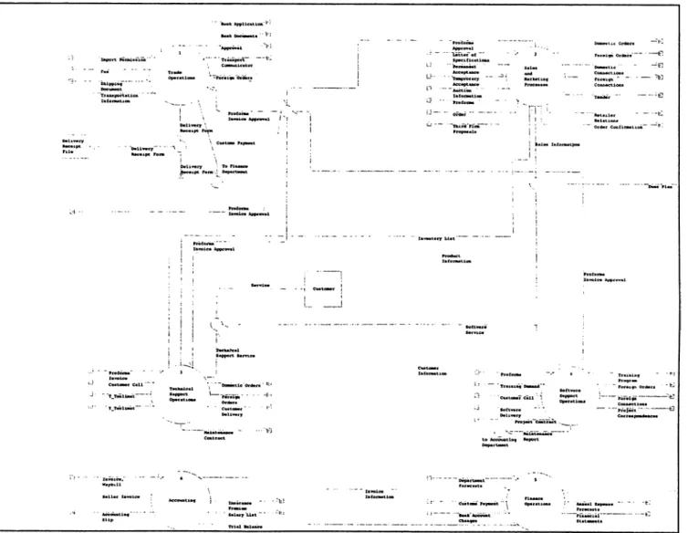
5.2 Information Services and Sales Operations
5.2.1 Trade DepartmentTrade Department is responsible for the processes that take place during the import of products by various departments. The departments confirm foreign orders to department managers. Trade Department assumes only confirmed orders as valid ones and do not take action if they are not currently confirmed by management. Foreign vendors send a proforma invoice for each order. These invoices are examined by ordering department. The Trade Department is told to continue \with the import after this examination.
Trade Department coordinates and controls the studies of picking the goods from foreign firm, transportation, and customs operations in Ankara. Many forms and documents are required for completing these steps successfully.
The department frequently contacts with finance department and three firms for its operations. Those firms are forwarder which transports the goods; customs commissioner which deals with customs bureaucracy; and insurance company which insures the products during transportation. Also, the department informs Finance Department about current and closing cash requirements like customs, freight, and insurance fees.
5.2.2 Sales and Marketing Department
Sales and Marketing Department sells computer systems by giving tenders. It prepares proposals to firms which are mostly government establishments according to their demand. Preparing a tender to public and private establishments are quite different in style. The public tenders have to fulfill each of the written technical requirements and have to be in a predefined style. Contrary to public proposals, tenders to private firms do not have a definite style.
Other group of products which are not as expensive as computer systems are sold via retailer channels. These product samples are plotters, printers, and optical readers.
The department is organized as manager, and sales support engineers. Each group of engineers work with a product manager. New products are marketed to potential customers with the leaderships of the managers. Every product manager and engineer deals only with his product range.
5.2.3 Hardware Support Department
The department deals with the hardware failures and perform periodic maintenance of the systems that were sold. Support engineers and technicians are employed for achieving these activities. It is the department manager's responsibility to arrange the schedules of his personnel. Also, the company warehouse is controlled and administered by the department. The material entrance and exit operations are controlled by the department manager.
The department generates income by providing service to customers and by selling new parts for replacing defective ones.
5.2.4 Software Support Department
Software Support Department performs support and project activities. Support activities involve the solution of software related problems of the system that are sold to customers. System support engineers work on these problems. Projects are custom software development studies that are done on a contract basis. A project team mostly consisting of engineers and programmers works on each project. The project teams are under the management of Software Support Department but the project manager has wide responsibility about the projects to customer and management. Their working place is usually the customer.
There is a company wide local area network and Internet connection. The PCs at each department use this structure. It is the Software Support Department's responsibility to keep the network running. If any problem emerges, support engineers solve it.
The training programs are scheduled and given to customers by the department. A training coordinator prepares the programs, assigns trainers and communicates with the customer. On programmed dates, courses are given to customer firm personnel at the company training room.
5.2.5 Finance Department
It is responsible for controlling the liquid assets,and providing necessary resources for the company. The cash of the company is distributed at various bank accounts both in local and foreign currencies. Everyday a small amount of cash is drawn for meeting the daily expenses. This amount is under the control of Accounting Department. Other cash in the accounts are
invested to government bonds, repo, and other funds and foreign currency. These operations are managed by Finance Department.
5.2.6 Accounting and Personnel Department
The department keeps the accounting books and personnel records that are legally required. The original accounting books are held at the company central office. So every accounting activity is recorded to accounting slips and sent to central office with original receipts and invoices. The copies are kept here for the department’s own control and for reporting to management.
N 5
CD
5.3 The Processes of Trade Department
5.3.1 Order Evaluation:
Input:
Proforma Invoice Approval Foreign Orders
Output: Order File
Property Equivalent Transfer List
The department performs the import operations for the foreign product orders given by other departments. The order forms are confirmed by the use of proforma invoice. Copies of foreign order forms and corresponding proforma invoices come from other departments. Trade department manager fills a record for each order to “property equivalent transfer list” (See Appendix A). All legal forms and documents related to each order are collected manually in a separate document file.
5.3.2 Bank Application: Input:
Bank Application (from bank)
Output:
Import Permission (to bank) Reference Number
The trade department applies to bank for import permission with the required documents. Standard application petition, proforma invoice, import duty receipt are transmitted to the bank with the petition. The import duty receipt value changes with the import method. The bank prepares a special document named as "Import Permission G copy". The company receives this document after a few days. If required, a qualification document that is obtained from ministry of trade might be asked by the bank. The bank gives a reference number® for every import action. Imports continue by using this number. The reference number that stands for each order is recorded to the necessary forms.
5.3.3 Transportation Follow-uo:
Input:
Forwarder Fax (from forwarder) Manufacturer Fax (from manufacturer) Transportation Information
Output:
Shipment Notification (to forwarder) Shipping Follow-up Update
Approval (to forwarder)
®After Customs Union, the reference number began to be given by the firm, not by the bank.
The forwarder firm gets the original invoice with the goods from the seller or manufacturer abroad. The invoice is sent via fax. Invoice shows the goods that are ready for shipping. A similar fax may come from the manufacturer. The invoice fax and proforma invoice is compared in order to prevent errors. If there is no error or inconsistency, the trade department tells the forwarder to start picking up and shipping the party of goods.
After the shipping is approved, the forwarder informs how the shipping will be made. Approximate arrival date is forecasted by using this information. Trade department manager appends this data to shipping follow-up form. The manager follows expected arrivals by attaching the forms on his wall. He makes the necessary changes on these forms until the goods come into the company's warehouse. This is a method that he developed by his experience. The airway bill or plate numbers, departure dates and some other information are required for insurance.
In “total in foreign currency” column of shipping follow-up (See Appendix A) form, only the transported material’s total price in USD is written. Sometimes the order is shipped in separate parties. Therefore “total in foreign currency” column's amount may be lower than the total value of the order.
5.3.4 Document Follow-up Input:
Related shipping follow-up form
Insurance Policy (from insurance agent) Shipping Document (from forwarder)
Output:
Insurance Data (to insurance agent)
Insurance Policy (to customs commissioner)
This is the stage that starts after sending the shipping order to forwarder and ends when the goods enter the customs house.
Required data is sent to insurance agent for the insurance policy. The data is obtained from the shipping follow-up form. Airway bill or plate number, departure date, approximate arrival date are some of the data elements available in the form.
The insurance agent insures the transfer and prepares the policy in a few days.
Insurance policy is given to the customs commissioner. Customs commissioner needs that form for clearing the goods through the customs.
5.3.5 Delivery Operations Input:
Goods Cleared from Customs Bill of Entry
Original Invoice
Output:
Legal Documents (to customs commissioner) Delivery Receipt Form
Customs Payment (to finance department) The necessary documents are transferred to the customs commissioner for the goods to clear through customs. Those documents are order, bill of freight, original invoice copy, import permission "G" copy, and legal capability document if required.
Finance department should know the approximate duty tax amount. The trade department calculates duty and other expenses like transportation, and insurance. Those calculations are not exact values but the deviation is usually around 5% of the exact amount. Trade department manager demands this money to be ready before the arrival of goods to customs. Trade Department organizes meetings with Finance Department in order to inform about the incoming parties of orders.
After clearing the goods through customs, the customs commissioner hands over them adding the bill of entry, cash receipt, original invoice and his invoice to the trade manager. Next, trade department sends the imported goods to hardware support department for routine control and tests. The part numbers and explanations of the sent goods are written in the delivery receipt form (See Appendix A).
Trade department gives copies of delivery receipt form to Hardware Support,and Accounting departments. The originals are filed in the department. Also the Sales Department orders' delivery receipt forms are sent to related sales representative. The sales department uses that form in cost analysis® of the sold properties.
5.3.6 Closing Bank Engagements: Input:
Original Invoice Approved by Customs Order file photocopies
Output: Petition
Customs Entrance Form Copy Customs cash receipt copy
' The expenses done during import are appended to the bottom part of the delivery receipt form.
A petition is sent to the bank through which import is done. The necessary document copies are also sent with the petition letter. This operation is done for closing the bank account that was opened for import.