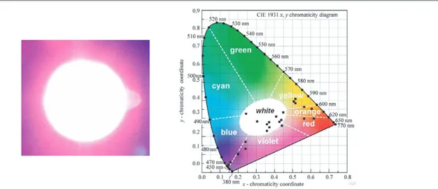
Nanocrystal-based hybrid white light generation with tunable colour parameters
Tam metin
Şekil
Benzer Belgeler
A more comprehensive explanation informed by critical approaches to security 15 reveals four interrelated problems: (1) the drawing up of the national security policy document
Performances of four methods of time-of-flight estimation for sonar signals are compared in terms of their bias, standard deviation and complexity: thresholding,
The Second Constitutional period and the early Republican period were quite fruitful in terms of the internationalization of the Turkish curriculum theory.. This period of
A DELETION MUTATION OF THE CONNEXIN 26 (GJB2) GENE IN A TURKISH PATIENT WITH VOHWINKEL SYNDROME Ozturk, S;Can, I;Eser, B;Yazici, H.. Genetic Counseling; 2016; 27, 2; ProQuest
41 Therefore, though acknowledging that the economic role of islands was not the same in the sixth century as in the eighth and ninth, this article will show that some
Once an accurate description of the ground-state quantities like pair distribution function is obtained from e.g., FHNC or QMC, the density–density response function and
The earliest Hittite presence on Kinet Höyük’s West Slope: plan of the Late Bronze I (Period 15) building in Ops... culture introduced in Period 15
The projected band diagram is a complicated way to explain the omnidirec- tional reflectivity inside transmission bragg fibers. In order to clarify the picture we prefer to use an
