FRESNEL LAMB WAVE A N D V-GROOVE LENSES WITH
TUNABLE MODE SELECTIVITY
G.G.
Yaralloglu,A .
Atalar,
H.
K oy m en El ec tr ica l a nd E lect ron ics E ng in eerin g D ep artm ent Bilkent University,06533
Bilkent, Ankara,TURKEY
Abstract ~ The Lamb wave and V-groove lenses are distinguished by their high surface wave exci- tation efficiencies. However, due t o t h e fixed in- cidence angle, a particular lens can only be used for materials having surface wave velocities within a limited range. Hence, it is desirable t o have lenses with adjustable incidence angle. Conven-
tional spherical lenses implemented in Fresnel pla- nar lens form have been demonstrated earlier. In this work, Lamb wave and V-groove lenses con- structed as Fresnel lenses are presented. We also discuss the feasibility of Fresnel lenses with air as the coupling medium. It is shown that it is possible t o build air coupled Fresnel lenses with a reason- able conversion efficiency into subsurface waves.
INTRODUCTION
The Lamb wave and V-groove lenses are powerful tools for material characterization and SAW ve- locity measurements [ l , 21. These lenses insonify the material surface at a fixed incidence angle and large amount of power is converted into the leaky gle does not match the critical angle for a leaky Lamb wave modes. However, if t h e incidence an- mode, leaky mode will not propagate along the material surface. For layered materials this diffi- culty can be overcome by adjusting the excitation frequency and modes can be generated selectively. For solid half spaces it is not possible t o gener- ate modes, once the incidence angle fails to match the critical angle. Fresnel version of Lamb wave and V-groove lenses solve the fixed incidence an- gle problem where the trade off is the degradation of sensitivity. Fresnel Lamb wave lens is composed of concentric conical surfaces such that height and the width of t h e cones are smaller than the acous-
b
Transducero
:
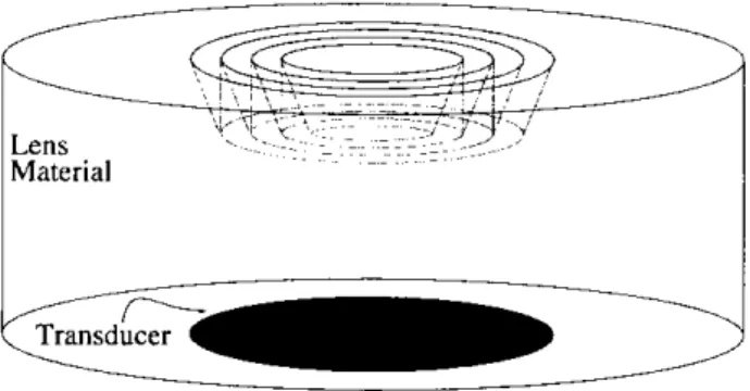
Figure 1: Fresnel Lamb Wave Lens
tic wavelength in the lens material. In the case of Fresnel \'-groove lens, the
V
shaped groove is re- placed by the smaller recesses. Fresnel lenses have planar geometries which make them suitable char- acterization tool in the air.In
the following sec-Then, Fresnel air transducers with high efficiencies tion, geometry of t h e lenses are described in detail. are introduced.
Lens
Material
!
Figure 2: Fresnel V-groove Lens
FRESNEL
LENSES
The Fresnel acoustic lenses with efficiencies up t o
80%
have been reported earlier[3].
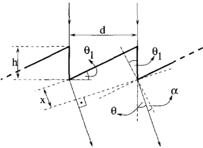
There, quadratic surfaces are approximated by a stair- case function suitable for silicon micromachining. Fresnel Lamb wave and Fresnel V-groove lenses can be constructed using the same method. Fig-ure 3 shows t h e cross section of a Fresnel lens.
Figure 3: Fresnel lens cross section
Planar geometry limits the hand width of th e lens. I f f designates the operation frequency, min- imnm allowable pulse width ( P W ) is
PW
= l n u m b e r of grooves.
f
(1)Beams refracted a t each sawtooth interfere COII- structively if:
k x
= 2T,
(2)where k = 27r f / V L and
V,
is the sound velocity in the coupling medium. The distance z is given bywhere
B1
is t h e wedge angle of the sawtooth, andB
is t h e incidence angle. With t,he substitution ( 3 )into ( 2 ) , incidence angle,
0,
is givenWe also write a simulation program which calcu- lates field distribution at the lens aperture. The
simulation program assumes unity field distribu- tion at th e back of the sawtooth like surface of th e lens and propagates the field through the refract- ing element by the ray theory. Fourier transform of aperture field shows the sngular spectrum of waves incident on the objcct surface.
40.0 j
F 35.0
:
\
~ ~simulation equation ~ .(4) .
9
".
experimentalFigure 4: T h e incidence angle of the acoustic beam refracted by the Fresnel lens.
Figure 4 shows the dependence of the angle t o th e frequency. The height, h , and the angle, 01, of the sawtooth are chosen as 0.45 mm and 30", respectively. Results of the F,q. 4 and simulation match very well. Experimental curve is obtained by calculating the period of t he oscillations i n V(z) curves from Fresnel Lamb wave lens by employ-
ing
FFT
based algorithm. The lens, with the di- mensions indicated in Figure 5, is f h r i c a t e d f r o m an aluminum block(Kens
= 6220 m/sec) by us- ing a precision lathe. In the experiments a trans- ducer with the center frequency a1 3.5 M H z is used and frequency is scanned from 3.1MHz
t o3.9
MHz.
For this frequency range, incidence an- gle changes from 29' t o 37'. Material under ob-Figure 5: Dimensions of t he Fresnel Lamb wave lens used in the experiments.
servation is brass which has a longitudinal criti- cal at around 20” and Rayleigh critical angle at around
50”.
Hence, with this lens neither longi-tudinal lateral wave nor Rayleigh wave is excited on the brass sample. So,
V(z)
oscillations are due to the geometrically reflected beams only and in- cidence angle is calculated by using th e following formula:0 = arccos
(
1 --
2
3
( 5 )where X. is the wavelength
i n
th e coupling fluid and A Z is the period of t he fringes in V(z) curve. Predictions of incidence angle by using theoretical and experimental curves are in agreement.1 w
(1.90 ;
-
7
t
simulatedFigure 6: T h e efficiency of t h e Fresnel lens T h e efficiency curve (Fig.
6 )
shows t,he amount of power sent in the direction of th e incidence an- gle. When frequency is equal t o 4.9MHz,
inci- dence angle predicted by Eq.1
matches with the angle calculated by Snell’s law at aluminum/water interface. At this frequency efficiency reaches its maximum value. For frequencies around 4.9 MHz efficiency drops and incidence angle deviates from t h e value calculated by Snell’s law.has a sawtooth like cross section. This geome- T h e Fresnel lens presented above discussions
-Zinc Oxide Transducer
Figure 7: Cross section of high frequency Fresnel Lamb wave or Fresnel V-groove lens.
t ry is suitable for the fabrication of low frequency lenses by using mechanical tools. High frequency
lenses can be produced by employing silicon mi- cromachining techniques. In this case sawtooth
like cross section of the Fresnel lens is approxi- mated by a stair case function. Figure 7 shows th e cross section of silicon micro-machined Fresnel Lamb wave or Fresnel V-groove lens which oper- ates at 200 MHz.
T h e lenses presented to this point use a liquid as coupling medium. It is also possible to pro- duce Fresnel lenses which uses air as t he coupling medium. In the next section Fresnel air transduc- ers are discussed.
FRESNEL
LENSES
AS
AIR
T R A N S D U C E R S
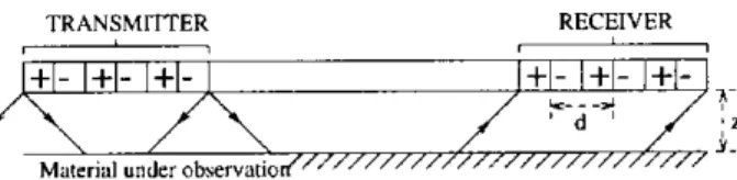
Fresnel Lamb wave or Fresnel V-groove lenses can be used as a n air transducers. These lenses can be manufactured by silicon micromachining as de- scribed in reference [4]. Fig. 8 shows the cross section of a two phase Fresnel air transducer.
TRANSMiTTER I -RECEIVER
-
+I- 1+1-
l+[-
I
[+l- /+l-
/+l-
k.. .? ‘ d ’ ?- : I Mnlerid vnderobrervilriod/7~~”~~”’”~”~’”~’”’~ Y.Figure 8: Cross section of a n air transducer Since geometry of t h e Fresnel lenses is planar, the distance between lens and the material can be made very small. Although the acoustic attenua- tion coefficient is very large, sound waves do not attenuate too much while propagating in the air. However, there is a problem a t air/solid interfaces. ficult to penetrate into the solids. Table 1 shows Due t o t h e high impedance mismatches, it is dif- typical two way loss values at air/aluminum and air/steel interfaces for excitation of bulk waves.
It is possible t o use leaky Lamb wave or
Rayleigh modes to increase subsurface excitation efficiency. The optimum transducer size to excite these modes is given by [5]
zu = 0.6282/1,, ( 6 )
where
h,
is t h e Schoch displacement and W is t hetransducer width. For solid/air interfaces Schoch displacement is around 400000X,;, which yields 8.6
300 pm at 10 MHz and minimum allowable pulse width,
( P W ) ,
is 10 psec.75.07 d B
CONCLUSION
oblique1
85.26 dBTable 1: Two way conversion losses for air/solid interfaces.
meter of transducer size a t l 0
MHz.
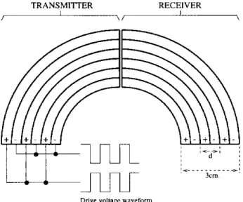
It is, of course? possible t o use small transducers with reduced ef- ficiencies. Normalized output voltage of a trans- ducer is calculated by using the following equa- tion [5]By using this formula the two way subsurface exci- tation efficiency of a 3 cm wide 10 MHz air trans- ducer for aluminum is calculated as -41 dB. In Fig- ure 9, a feasible Fresnel Lamb wave air t,ransducer is shown. Air transducer has separate pieces for transmitting and receiving sound waves t o avoid receiving specular reflections from the object s u r - face.
&
&
TRANSMITTER RECEIVER
Drive voltage waveform
Figure 9: Fresnel Lamb wave air transducer, The distance d (Fig. 9) is given by:
L i r
d = ~ sin BR
For airlaluminum interface Rayleigh critica.1 an- gle, BR, is around 6.6’. Hence, d is calculated as
In
this study, Fresnel Lamb wave and Fresnel V- groove lenses are introduced. The main advantage of these lenses is that they release the fixed inci- dence angle restriction of the Lamb wave and V- groove lenses. Incidence angle of th e Fresnel lenses changes with the excitation frequency. However,their leaky wave excitation efficiencies are lower than that of Lamb Wave an d V-groove lenses. are difficult to fabricate by mechanical means for
Conventional Lamb wave and V-groove lenses high frequency applications. On the other hand, Fresnel lenses have planar geometries, hence they can be fabricated on silicon wafer using microma- chining techniques. Moreover, it is also possible
t o build high efficiency air transducers in Fresnel in [4] a t low MHz range. With thcse transducers, Lamb or V-groove lens forms using methods given much lower two way loss for the excitation of Lamb wave modes can be achieved.
Acknowledgment
This work is supported by Turkish Scientific and Technical Research Council,
TUBITAK.
References
[ l ] A. Atalar,
H.
Kiiymen, F.L. Degertekinl“ A
lamb wave lens for Acoustic Microscopy”,IEEE
Tmnans.UFFC,
Vol. 39, No. 6. PP. 661- 667, 1992.[2] A. Bozkurt,
G.G.
Yaralioglu, A. Atalar, H. Koymen, “A new directional acoustic lens: V-. _ .
groove lens”, i n IEEE Crltlasonic Pmceedinys,
[3] B. Hadimioglu,
E.G.
Rawson,R.
Lujau It., 1993.M. Lim,
J.C.
Zesch, R.T. Khnri-Yakub,C.F.
Quate, “High efficiency Fresnel acous- tic lenses”, inIEEE
Ulfrusonic Proceedings,1993.
[4] M.I. Haller, B.T. Khuri-Yakub, “A surface micro-machined electrostatic ultrasonic air
transducer”, in
IEEE
Ultrasonic Proceedings.1994.
[5] A. Atalar, H. Koymen, “Use of a conical