0885–3010/$25.00 © 2010 IEEE Abstract—In this work, we propose a novel method to
in-crease the quality factor of extensional mode micromechanical resonators. The proposed resonator topology is suitable for integration in a silicon-based process to fabricate microme-chanical filters and oscillators. It is a half-wavelength-long strip excited longitudinally by electrostatic forces, and it is isolated from the substrate by alternating with bars of a quarter wave-length long. This structure causes a large impedance mismatch between the resonator and the substrate and hence reduces the anchor loss considerably. The performance of the resonator is determined by finite element simulations. We introduce an equivalent electrical circuit to predict the performance of the resonator. The electrical model gives results consistent with the finite element simulations. The proposed resonator is ex-pected to have a very small anchor loss resulting in a very high Q.
I. Introduction
M
icromechanical filters have been fabricated by integrated circuit compatible techniques [1], which showed their potential to replace off-chip surface acoustic wave or crystal filter counterparts. To have high frequency selectivity, the resonators of the filter should have high quality factors on the order of 10,000 [2] to be used in ra-dio frequency applications. The energy dissipation mecha-nisms that determine the quality factor in micromachined structures are air damping, anchor loss, thermoelastic dis-sipation, surface loss, and internal (material) dissipation [3]. bulk mode extensional resonators have reached very high quality factors [4]. Their stiffness, in the order of 106n/m, enables such resonators to store a high amount of energy. With this characteristic, in contrast to the flexural resonators, bulk extensional resonators can achieve very high q values with the same amount of air damping per cycle [1], [5].
at high frequencies, the main loss mechanism that de-termines the q value in extensional mode resonators is the anchor loss [6]. several designs have been implemented to eliminate the anchor loss in micromachined structures. resonators have been anchored to the substrate at their nodal points [1], [7] to reduce the energy coupled to the substrate. Techniques based on impedance mismatch have
been used in several designs. newell suggested using bragg reflectors composed of different material types [8]. Wang et al. have implemented material mismatched disk resona-tors [9]. Impedance mismatch between the polysilicon and the diamond reduced anchor loss considerably, and a q value of 11 555 was obtained at 1.5 GHz. The reflection property of the quarter-wavelength beams was used to re-duce support loss in [10]. In another work, thinner beams were used to attach bulk micromachined resonators to the substrate [11].
In this paper, we introduce a new isolation mechanism to eliminate anchor loss. We use quarter-wavelength long strips with alternating low and high impedances to trans-form the impedance of the substrate to a very small value. Hence, the anchor of the resonator is connected to a very low impedance, and very little energy coupling occurs. be-cause the impedance of a strip is proportional to the cross-sectional area of the strip, we use alternating width strips with the same thickness to decouple the resonator from the substrate. no other material type is required, and the fabrication process is relatively simple. In what follows, we will explain a reflection mechanism in mechanical bars. based on this mechanism, we will introduce a novel meth-od to connect the resonator to the substrate to reduce the anchor loss. an electrical equivalent circuit will be presented to predict the behavior of the resonator without finite element simulations. Finally, simulation results will be presented showing the performance of the resonator.
II. analogous Electrical circuit
let us first investigate the acoustic wave propagation in a thin rod. There may be several modes present in a thin rod depending on the frequency of excitation. In rectangu-lar rods, the zeroth-order longitudinal mode propagation is nondispersive [12]. Higher and dispersive modes are ex-cited above a certain frequency. below this frequency, all dispersive modes are evanescent. If the length of the rod, L, is much greater than its width, W, and its thickness, T (T < W), the closest higher order plate mode resonance occurs at f1 =fo 1+( /L W)2 [12] where fo is the fre-quency at which L equals λ/2. If L/W is sufficiently large, f1 is far away. In this work, we assume an operation below
f1 and approximate 3-d waves in the rod with 1-d zeroth
order longitudinal (extensional) waves. Finite element simulations (ansys, Inc., canonsburg, Pa; see Fig. 1) of rods with modest L/W ratios show that the waves in the rods are not strictly longitudinal. nevertheless, the ap-proximation gets better as the L/W ratio is made higher.
Reducing Anchor Loss in Micromechanical
Extensional Mode Resonators
Vahdettin Taş, selim olcum, Student Member, IEEE, M. deniz aksoy, and abdullah atalar, Fellow, IEEE
Manuscript received May 16, 2009; accepted october 20, 2009. V.T., s.o., and M.d.a. gratefully acknowledge the financial support of TUbI-TaK and asElsan a.s. for their graduate study scholarship programs. a.a. acknowledges the support of TUba. This work was supported by TUbITaK under project grant 107T921.
The authors are with the Electrical and Electronics Engineer-ing department, bilkent University, ankara, Turkey (e-mail: vtas@ ee.bilkent.edu.tr).
nondispersive wave propagation in these mechanical rods are analogous to wave propagation in electrical trans-mission lines.1 counterparts of force and particle velocity
in the mechanical domain are voltage and current in the electrical domain, respectively. Hence, the characteristic impedance (Z) of a transmission line is the analog of the mechanical characteristic impedance of a rod. Z of a rod for the zeroth-order nondispersive mode can be written as a frequency independent parameter [13]
Z AE
c A E
= = r, (1)
where A = WT is the cross-sectional area of the rod, E is the young’s modulus, ρ is the density of the rod, and c is the phase velocity of the extensional mode with c = E/r. Z has the unit of kilograms per second. Fig. 2 illustrates an infinitely long rod connected to another rod of the same thickness but of a smaller width. A1 and A2
represent the respective cross-sectional areas of the rods. When an extensional mode stress wave is incident from the first rod to the second rod, the stress wave is reflected with a reflection coefficient of R and is transmitted to the second region with a transmission coefficient of T:
R Z Z Z Z T Z Z Z = 2 1 = 2 1 2 2 1 2 -+ + , (2)
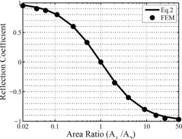
where Z1 and Z2 represent the respective mechanical char-acteristic impedances of the rods. It is clear from this equation that Z1/Z2 = A1/A2 must be made as away as possible from 1 to minimize the transmitted power. a transient analysis was done to examine the validity of (2) using the finite element package. Fig. 3 shows the re-flection coefficient of stress waves along the axis of the rod from finite element simulations in comparison to that from (2) for various A1/A2 values. We can see that the first order approximation of (1) is valid in a wide range 0.02 < Z1/Z2 < 50.
The rods are typically connected to a substrate at one end to form a resonator. If the substrate is sufficiently large, any energy coupled to the substrate can be consid-ered to be lost. Hence, the substrate connection can be modeled as a resistance in the analogous electrical circuit. To complete the picture, we need to express the value of this resistance in the mechanical domain.
suppose that the attachment point vibrates in response to uniform axial stress of σx at the clamped end. The cor-responding force at the attachment is σxA. To calculate the displacement of the attachment, Hao et al. [14], [15] model the support as an infinite elastic medium. For a circular2 cross section of area A, the displacement of the
attachment point is given by [14]
Fig. 1. Finite element simulations showing the standing waves in rods of different L/W ratios.
Fig. 2. Incident, reflected (R) and transmitted (T) stress waves at a discontinuity in an acoustic bar of uniform thickness, T.
Fig. 3. calculated (solid line) and simulated (dots) reflection coefficient of stress wave as a function of area ratio.
1 because the electrical transmission lines are nondispersive, it is not
possible to represent dispersive acoustic modes with a transmission line analogy.
2 a rectangular cross section with the same area should give the same
results as long as the cross-sectional dimensions are much smaller than the wavelength. However, this statement is inconsistent with the results in [14]. comparison of 3-d FEM simulations with circular and rectan-gular cross sections showed that the results are within 2% of each other, rather than the 2π ratio existing between (37) and (46) of [14].
u A F c x x t = ( ) 2 3 s wg g pr , (3) with ct = 2 (1r E+n), (4) g n n = 2(1 ) 1 2 -- , (5)
where ν is the Poisson ratio of the rod material and w is the angular excitation frequency. F(γ) is given by the imaginary part of an integral [14]:
F( ) = Im ( 2 ) 4 0 2 2 2 2 2 2 g kz g z kz z g dz ¥
ò
- - - , (6) with k= z2- .1at this point we can define the equivalent resistance, R, representing the energy lost into the substrate. Its val-ue can be found by dividing the force, σxA, by the particle velocity, ωux: R c F Kc t =2 ( ) 1 = 4 3 2 2 p r g g w pr l , (7) where K F = 1 16 2g g( )(1+n)3 2/ . (8)
The unit for R is kilograms per second, and it is consistent with the unit of Z. It is clear that R can be made large by choosing a high stiffness, low-density material. We note that the quantities Z/A and R/λ2 are dependent only on
the material constants. Values of K, Z/A, and R/λ2 for
several materials are listed in Table I.
III. Mechanical quality Factor of suspended resonators
A. Quarter-Wavelength Resonator
First, let us consider a quarter-wavelength long, L = c/ (4f) = λ/4, resonator connected to a substrate at one end as shown in Fig. 4. The analogous electrical circuit is de-picted in the same figure. The resonator and its substrate connection are modeled by an electrical transmission line
and a resistor, respectively. To get a high quality factor, the condition R ≫ Z0 is imposed. The electrostatic
exci-tation force of the mechanical resonator is represented by a voltage source in the electrical equivalent. To determine the quality factor of this circuit, the impedance seen by the voltage source is written from the transmission line equation [16] as Z Z R jZ f f Z jR f f in0 0 0 0 0 0 = ( 2 ) ( 2 ) + + tan tan , p p / / (9)
where f is the operation frequency and f0 is the frequency
at which the transmission line is a quarter wavelength. If f is close to f0, tan(πf/2f0) ≈ 2f0/(π(f0 − f)) and it is very
large. Using this approximation and ignoring the real part of the denominator, (9) becomes
Z Z R jZ f f f jR f f f Z R j Z f f f in0 0 0 0 0 0 0 02 0 0 0 2 ( ( ) 2 ( ( ) = 2 » + -- -/ / p p p ) ) . (10) at 3-db frequencies (f1 and f2), the real part of Zin will be equal to the absolute value of the imaginary part:
Z R Z f f f Z f f f 02 0 0 1 0 0 2 0 0 = 2 = 2 p - p -. (11)
The quality factor, Q0, is the center frequency divided by the 3-db bandwidth: Q f f f R Z 0 0 2 1 0 = = 4 -p . (12)
TablE I. Values of constants for different Materials.
Material K Z/A (kg/m2/s) R/λ2 (kg/m2/s) silicon oxide 0.112 1.24 · 107 1.77 · 106 silicon 0.101 1.86 · 107 2.41 · 106 Polysilicon 0.107 1.92 · 107 2.62 · 106 silicon nitride 0.106 2.78 · 107 3.75 · 106 Polydiamond 0.118 6.20 · 107 9.33 · 106
Fig. 4. a λ/4 mechanical resonator with a cross-sectional area of A0 and
Hence, the quality factor of the mechanical resonator due to anchor loss can be deduced by combining (1), (7), and (12): Q K A 0 2 0 = l . (13)
It is clear that a high value of λ2/A0 will result in a better
quality factor. The resonator should have as small cross section as possible.
B. Half-Wavelength Resonator
In this case, L = c/(2f) = λ/2. The quality factor of the resonator from the electrical circuit can be deduced using a derivation similar to that given above:
Q Z R = 2 1 p . (14)
From (1) and (7) we find Q K A = 8 2 1 2 p l . (15)
In this case, A1/λ2 must be large to have a high quality
factor resonator. However, this requirement contradicts with the requirement that the length of the resonator should be much longer than its width to guarantee zeroth-mode operation. We conclude that a half-wavelength rod connected to a substrate directly does not result in a high Q resonator.
C. Half-Wavelength Resonator Supported with a Quarter-Wavelength Bar
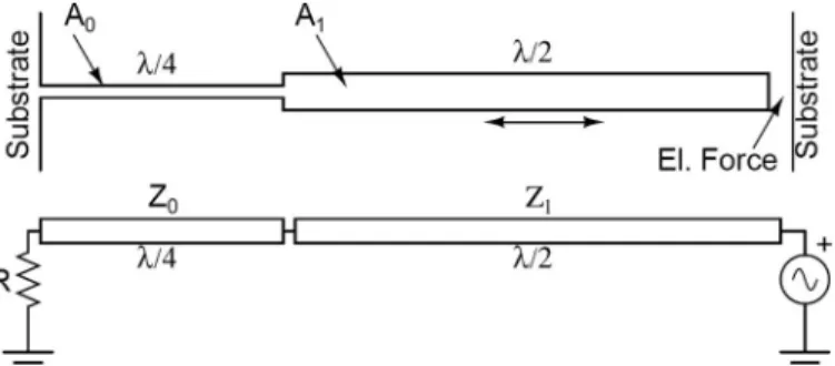
a half-wavelength resonator is connected to the sub-strate through a quarter-wavelength bar with A1 > A0 as illustrated in Fig. 5. The electrical equivalent circuit can be analyzed to determine the quality factor. The imped-ance, Zin1, seen by the voltage source is
Z Z Z jZ f f Z jZ f f in in in 1 1 0 1 0 1 0 0 = ( ) ( ) + + tan tan . p p / / (16)
The imaginary part in the denominator can be ignored when f is near f0, because Z1≫ Zin0. substituting (10) in (16) and using tan(πf/f0) ≈ π(f − f0)/f0 we find
Z Z R j Z f f f j Z f f f in1 0 2 0 0 0 1 0 0 = 2 - p - + p - . (17)
Equating the real part to the imaginary part to find the 3-db frequencies Z R Z Z f f f Z Z f f f 02 0 1 0 1 0 0 1 2 0 0 = 2 = 2 p p p p + æ è çç öø÷÷÷ - æèçç + öø÷÷÷ - . (18) Hence, Q of this circuit is given by
Q R Z Z Z 1 0 1 0 = 4 1 2 p + æ è çç ç ö ø ÷÷÷÷. (19)
Using (1) and (7) we find
Q K A r 1 2 0 = l
(
1+2)
, (20)with r = A1/A0. clearly, the quality factor improves with (1 + 2r). Making the area ratio r as large as possible will result in a high Q resonator.
D. Half-Wavelength Resonator Supported with 3 Quarter-Wavelength Sections
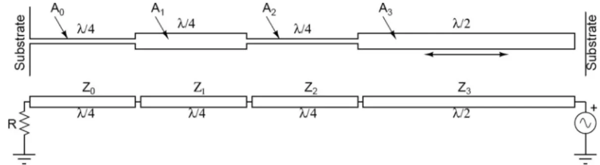
We can add 2 more quarter-wavelength sections to im-prove the quality factor even more as shown in Fig. 6. The half-wavelength resonator is connected to the substrate through 3 quarter-wavelength sections. From the electrical circuit of this combination we find
Q R Z Z Z Z Z Z Z Z Z 2 0 1 0 2 0 3 0 1 2 2 = 4 1 2 p + +æèççç + öø÷÷÷æèççç öø÷÷÷ æ è çç çç ö ø ÷÷÷÷ ÷. (21) Using (1) and (7), we find
Q K A A A A A A A A A 2 2 0 1 0 2 0 3 0 1 2 2 = l æççççè1+ +æçççè +2 öø÷÷÷èçççæ ÷÷÷øö öø÷÷÷÷÷. (22) This equation shows that the area ratio between neigh-boring elements must be large to generate a high-quality system. For the special case of r = A1/A0 = A3/A2 with A0 = A2, we find Q K A r r r 2 2 0 2 3 = l (1+ + +2 ). (23)
With a modest area ratio of r = 5, the improvement in the quality factor is 281. Harmonic analysis was done in the FEM simulator to observe the amount of stress at the clamped region. The stress at the anchor point is
mini-Fig. 5. a λ/2 resonator supported with a λ/4 bar and its electrical equivalent circuit.
mized by successful operation of the quarter-wavelength sections.
E. Half-Wavelength Resonator Supported with an Odd Number of Quarter-Wavelength Sections
We can generalize the formula of (23) to n pair of reso-nators as follows: Q K A r r r r n = (1 ... n 2 n ) 2 0 2 2 2 2 1 l + + + + - + - . (24) F. Odd-Overtone Resonances
The structures above resonate also at an odd multiple of the fundamental frequency. The corresponding quality factor at those frequencies can be determined easily from the electrical equivalent circuit. If the overtone resonance is at (2m + 1) multiple, the quality factors of electrical equivalent circuits as given by (12), (19), and (21) predict a quality factor improvement of (2m + 1). However, the
anchor loss represented by R is proportional to λ2, and
hence R decreases by the factor (2m + 1)2 at these
odd-overtones. We conclude that in all the structures above the quality factor at the (2m + 1)th resonance is reduced by a factor of 1/(2m + 1). so, using overtone resonances is not advantageous. For example, the resonator of Fig. 5 (3λ/4 long) is better than a uniform 3-quarter-wavelength (third-overtone) resonator.
IV. simulation results
We have verified the validity of (13), (20), and (23) by a finite element simulator. We used coMsol (coMsol, Inc., burlington, Ma)because it can handle a propagation into a semi-infinite medium very well. Perfectly matched layers (PMl), which are constructed by complex coordi-nate transformation, have been implemented to find an-chor loss [17]. In the FEM package, PMl domains are available for several analysis types. We worked with reso-nators with circular cross sections rather than rectangular to get axially symmetric structures for a better accuracy.
Fig. 6. a half-wave resonator supported with 3 quarter-wave sections and its equivalent circuit.
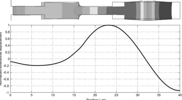
Fig. 7. deformed and undeformed shapes of the λ/2 resonator supported by a λ/4 section as found from FEM. lower figure is the displacement amplitude along the axis of the bars.
We applied a uniform force parallel to the axis of the reso-nator at the free end to simulate the typical electrostatic excitation. Fig. 7 illustrates the deformed and undeformed shapes of a λ/2-long 250-MHz resonator supported by a λ/4 section. The same figure also has a plot of the dis-placement amplitude along the resonator. Fig. 8 contains similar figures for the same resonator supported by 3 quar-ter-wave sections. clearly, the displacement amplitude at the anchor gets smaller with more support sections.
We performed frequency response analysis to extract the quality factor. Fig. 9 is a comparison of Q values due to anchor loss, as obtained from the analytical expressions and the finite element simulation results. The quality fac-tor of a silicon quarter-wave resonafac-tor at 250 MHz is plot-ted in the lower curve. For the half-wavelength resonator supported by a quarter-wavelength bar we chose r = 4. Eq. (20) is plotted along with finite element simulation results in the middle of Fig. 9. In the same figure, a half-wavelength resonator with 3 quarter-wave support rods is also shown. We chose A0 = A2, A1/A0 = 6.25, and A1 = A3 (r = 6.25). differences between the curves and FEM results can be attributed to the errors in simulations and deviations from the transmission line approximations as λ2/A
0 ratio decreases.
The proposed resonant structures can be fabricated us-ing a variety of available micromachinus-ing processes includ-ing [1] and [7]. a typical silicon half-wavelength resonator at 250 MHz should be 16-μm long and several microns wide.
V. conclusions
a new method has been proposed to reduce anchor losses in micromachined structures. The method is supe-rior to other isolation methods in terms of ease in the fabrication processes. an electrical equivalent circuit is introduced with a resistance modeling the anchor loss. Equations predicting the quality factors of extensional resonator with different support structures are derived. The formulas are optimistic because they include only the anchor loss. The FEM simulation results are consistent with the predictions. The proposed resonator structure is
Fig. 8. deformed and undeformed shapes of the λ/2 resonator supported by 3 λ/4 sections as found from FEM. lower figure is the displacement amplitude along the axis of the bars.
Fig. 9. a comparison of finite element simulation results with the ana-lytical formula: Q of silicon resonators for varying λ2/A0 ratios. Q0 of a
quarter-wave resonator (lower curve), Q1 of half-wave resonator with one
λ/4 support with r = 4 (middle curve), and Q2 of half-wave resonator with 3 λ/4 supports with r = 6.25 (upper curve). E = 150 GPa, ρ = 2330 kg/m3, and ν = 0.3 have been used for the silicon material properties.
a promising high-q building block in rF micromechanical filters and oscillators.
acknowledgments
We thank the reviewers for very helpful comments. references
[1] J. clark, W.-T. Hsu, M. abdelmoneum, and c.-c. nguyen, “High-q UHF micromechanical radial-contour mode disk resonators,” J.
Microelectromech. Syst., vol. 14, no. 6, pp. 1298–1310, dec. 2005.
[2] c.-c. nguyen, “Frequency-selective MEMs for miniaturized com-munication devices,” in Proc. IEEE Aerospace Conf., vol. 1, Mar. 1998, pp. 445–460.
[3] K. yasumura, T. stowe, E. chow, T. Pfafman, T. Kenny, b. stipe, and d. rugar, “quality factors in micron- and submicron-thick can-tilevers,” J. Microelectromech. Syst., vol. 9, no. 1, pp. 117–125, Mar. 2000.
[4] T. Mattila, J. Kiihamki, T. lamminmki, o. Jaakkola, P. rantakari, a. oja, H. sepp, H. Kattelus, and I. Tittonen, “a 12 MHz micro-mechanical bulk acoustic mode oscillator,” Sens. Actuators A Phys., vol. 101, no. 1–2, pp. 1–9, 2002.
[5] y. Xie, s.-s. li, y.-W. lin, Z. ren, and c.-c. nguyen, “1.52-GHz micromechanical extensional wine-glass mode ring resonators,”
IEEE Trans. Ultrason. Ferroelectr. Freq. Control, vol. 55, no. 4, pp.
890–907, apr. 2008.
[6] J. Wang, Z. ren, and c.-c. nguyen, “1.156-GHz self-aoligned vi-brating micromechanical disk resonator,” IEEE Trans. Ultrason.
Ferroelectr. Freq. Control, vol. 51, no. 12, pp. 1607–1628, dec.
2004.
[7] s. Pourkamali, Z. Hao, and F. ayazi, “Vhf single crystal silicon ca-pacitive elliptic bulk-mode disk resonators-part II: Implementation and characterization,” Microelectromech. Syst. Journalism, vol. 13, no. 6, pp. 1054–1062, dec. 2004.
[8] W. newell, “Face-mounted piezoelectric resonators,” Proc. IEEE, vol. 53, no. 6, pp. 575–581, Jun. 1965.
[9] J. Wang, J. butler, T. Feygelson, and c.-c. nguyen, “1.51-GHz nanocrystalline diamond micromechanical disk resonator with ma-terialmismatched isolating support,” in Proc. 17th IEEE Int. Conf.
Micro Electro Mechanical Systems, 2004, pp. 641–644.
[10] s.-s. li, y.-W. lin, y. Xie, Z. ren, and c.-c. nguyen, “Micro-mechanical ‘hollow-disk’ ring resonators,” in Proc. 17th IEEE Int.
Conf. Micro Electro Mechanical Systems, 2004, pp. 821–824.
[11] W. Pang, H. Zhang, and E. s. Kim, “Micromachined acoustic wave resonator isolated from substrate,” IEEE Trans. Ultrason.
Ferro-electr. Freq. Control, vol. 52, no. 8, pp. 1239–1246, aug. 2005.
[12] K. F. Graff, Wave Motion in Elastic Solids. oxford: clarendon Press, 1975.
[13] a. alastalo, T. Mattila, and H. seppa, “analysis of a MEMs trans-mission line,” IEEE Trans. Microw. Theory Tech., vol. 51, no. 8, pp. 1977–1981, aug. 2003.
[14] Z. Hao and y. Xu, “Vibration displacement on substrate due to time-harmonic stress sources from a micromechanical resonator,” J.
Sound Vibrat., vol. 322, no. 1–2, pp. 196–215, 2009.
[15] Z. Hao and F. ayazi, “support loss in the radial bulk-mode vibra-tions of center-supported micromechanical disk resonators,” Sens.
Actuators A Phys., vol. 134, no. 2, pp. 582–593, 2007.
[16] d. M. Pozar, Microwave Engineering. new york: John Wiley and sons, Inc., 1998.
[17] s. G. david and s. bindel, “Elastic PMls for resonator anchor loss simulation,” Int. J. Numer. Methods Eng., vol. 64, no. 6, pp. 789–818, 2005.
Vahdettin Tas received a b.s. degree from
Mid-dle East Technical University, ankara, Turkey, in 2007 and an M.s. degree from bilkent University, ankara, Turkey, in 2009, both in electrical engi-neering.
He is currently working toward his Ph.d. de-gree in the department of Electrical Engineering and computer science at the University of cali-fornia, berkeley, ca. His current research inter-ests include micromechanical signal processors and microwave electronics.
Selim Olcum was born in chicago, Il, in 1981.
He received his b.s. and M.s. degrees in electrical engineering in 2003 and 2005, respectively, both from bilkent University, ankara, Turkey.
Mr. olcum worked as a guest researcher at the national Institute of standards and Technol-ogy, semiconductor Electronics division, during the summers of 2002 and 2003. He was a visit-ing scholar at the Micromachined sensors and Transducers laboratory of the Georgia Institute of Technology, atlanta, Georgia, in 2006. He is currently working toward his Ph.d. degree in the Electrical and Elec-tronics Engineering department at bilkent University where he has been a research and teaching assistant since 2003.
His current research interests include optical and acoustical micro-machined sensors and actuators. Mr. olcum is a recipient of the asEl-san Ph.d. scholarship. He has been a member of IEEE and the UFFc society since 2003.
M. Deniz Aksoy was born in Izmir, Turkey, in
1984. He received his b.s. degree in electrical en-gineering in 2007 from bilkent University, ankara, Turkey. He is currently working toward his M.s. degree in the same department where he has been a research assistant since 2007. His research inter-ests include micromachined sensors, atomic force microscopy, and nano-characterization.
Abdullah Atalar received his b.s. degree from
Middle East Technical University, ankara, Tur-key, in 1974 and his M.s. and Ph.d. degrees from stanford University, stanford, ca, in 1976 and 1978, respectively, all in electrical engineering. From 1978 to 1980, he was first a postdoctoral fellow and later an engineering research associate at stanford University. For 8 months, he was with Hewlett Packard labs, Palo alto, ca. From 1980 to 1986, he was on the faculty of the Middle East Technical University as an assistant professor. In 1986, he joined bilkent University, ankara, Turkey, as chairman of the Electrical and Electronics Engineering department and served in the founding of the department where he is currently a professor. He is pres-ently the Provost of bilkent University. From 1996 to 1998, he was a visiting professor at stanford University. His current research interests include microwave electronics and micromachined sensors. He was awarded the science award of Turkish scientific research council (TUbITaK) in 1994. He is a fellow of IEEE and a member of the Turk-ish academy of sciences.