Reflection of ultrasonic waves at a liquid-cubic-solid interface
Abdullah AtalarMiddle East Technical University, Electrical Engineering Department, Ankara,, Turkey
(Received 16 May 1982; accepted for publication 27 September 1982)
The results of numerical calculations are presented for the reflection coefficient of sound waves incident on a liquid-cubic-solid interface. The reflection coefficient is calculated numerically for the (001) face ofvarious cubic crystals. It is found that for certain orientations there is a null in the reflection coefficient. At this orientation all the power is coupled into a quasishear wave inside the solid. An explanation based on impedance theory is presented. The explanation given predicts
that there
might
be reflection
nulls
for other
liquid-solid
interfaces
where
the solid
is any
anisotropic solid not just cubic.PACS numbers: 43.20.Fn, 68.45. -- v, 43.20.Bi
INTRODUCTION
The reflection coefficient at a liquid-solid interface
proved
to be an important
quantity
for the characterization
of the solid. It is found that the material properties influencethe reflectance of bounded beams incident on the interface
near
the Rayleigh
critical
angle.
•-3 The transition
of the re-
fiection coefficient phase causes a lateral displacement of theincident
beam
known
as
the
"Schoch
displacement."
In fact
this displacement
is proportional
to the slope
of the phase
transition. 4
Most of the work relating to the reflection coefficient at
a liquid-solid
interface
was
limited
to isotropic
solids.
For
that case
explicit
expressions
can
be derived
for the reflection
coefficient and also for the Schoch displacement. For aniso-tropic
media
an analytic
expression
is hard to obtain
and
therefore numerical methods must be utilized. In this paperthe simplest
anisotropic
crystal
will be considered:
the re-
flection coefficient will be calculated for the (001} face of acubic
crystal.
The media
will be assumed
lossless
and piezo-
electricity will be neglected.I. METHOD OF SOLUTION
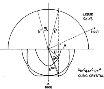
Consider
the geometry
of Fig. 1 where
the axes
are cho-
sen such that the x axis coincides with [100], y axis withLIQUID
Co
,7o
x oo] c•,c44,c•2,Jø CUBIC CRYSTAL z [ooflFIG. 1. Acoustic plane-wave scattering at a liquid-cubic-crystal interface. Wave vectors along with slowness surfaces are shown. Interface is the (001)
face of the cubic crystal.
[010], and z axis with [001] direction
of a cubic
solid.
Sup-
pose that a unit amplitude plane wave is incident at the liq- uid-solid interface at z = 0. The liquid is characterized by its stiffness constant Co and density Po, and the cubic solid is characterized by three stiffness constants c•, c•2, c4n, and density p.The particle velocity field of the incident wave is written
as
v • = (k z/ko)exp(ffkz.
r), with r = x• + yp + z•,
where k • is the wave vector,/Co is the wavenumber in the liquid, and •, j, and • represent the unit vectors.Referring to Fig. 1, one reflected wave in the liquid and three refracted---one quasilongitudinal (QL} and two quasi- shear (QS}-waves in the solid can be present. The corre- sponding velocity fields can be written as
v • = R (k •/ko)exp(jk•.r),
v L = L¾
L exp(jkL.r),
rs, = S 1¾s' exp(jkS,.r),v s• = S 2y s2 exp{jkS2.r),
where k a, k L, k s ', and k s2 are the wave vectors of the reflect- ed wave in the liquid and of the QL and two QS waves in the solid, respectively. R, L, S 1, and S 2 stand for the complex
amplitudes
of the respective
waves.
¾L,
¾s,, and yS• are the
unity polarization vectors of the refracted waves. In generalyL is not in the same
direction
as k œ
for a QL wave,
and ¾s,
and ¾s• are not necessarily
normal
to k s' and k s• for QS
waves.
Using
the abbreviated
subscript
notation
of Auld
5 the
boundary conditions on the velocity and stress become(r; + rg) l=o = (rS +
+
First boundary condition gives
k'.r = ka.r = kL.r = k s"r = kS2.r, or J = 3,4,5. {21 at z----O k • =ka=k X X L =k s' =kS2=l•k X X X O• •
ß =k•=k L =k s' =kS•=lyk
where lx and ly are direction cosines of the incident wave.
Knowing the x and y components of the wave vector of all the possible waves, we now have to determine the z com- ponents. In the liquid we have
2}1/2
I = (ko
• _ k 2 _ k•)l/2 ko(1
- l• - ly
,
R=
and kz z ß
The propagation characteristics of plane waves in the anisotropic solid can be found by the Christoffel equation:
k 2Fov
j = pr_o2vi,
where
F• is the Chfistoffel
matrix.
• A dispersion
relation
can be obtained by setting the characteristie.dete•inant equal to zero:
--
I = 0.
(3)
From this k 2/02 can be solved through a third-order equa- tion if the direction cosines of the propagation direction
(1•
,1•,1•)
are known.
Since
the direction
of the k vector
in the
solid side is still unknown, we prefer to write •. (3) in the following fo•:-
I = 0,
(4)
which follows from the prope•y of the Chfistoffel matrix
that
k 2F•(I•,I•,I•)
= F•(k•,k•,k•
). In general,
Eq. (4)
gives
a
sixth-order
equation
in k•.• The six roots
of k• define
those
wave vectors that can satisfy the condition of having equal components of phase velocity parallel to the bounda• plane. For a cubic c•stal •. (4)can be written as the square of a cubic polynomial. Hence we have to solve only a third- order equation: Ih
x q-½44(hy
q-hz)/½11-
1
(C•2
-+-
c44)(hxhy}•/2/c•!
(C
12
-!- C44)h
xl/2•
'/CI1
(C12
+ c44)(hxhy)l/2ffCl,
hy + c44(h
x + hz}/cl,- 1
(C 12 + c44}h y 1/2•'/C :• 1 I where 2--
2 hz Cllkz
hx- poC•
12 hy poC•
ly,
P½o
P½o
P 0)2
and• = {CllC,•4
+ C]I C44
-- C44C122
-- 2CLC,2}/C•
3, ,
B = (c•
3, + 4c344
+ 2c•3•
-- 3c,,c•2
-- 6CllC12C44
+ 6chc44
+ 6c,,& I/c3,,
C= {2C•C44 -[- C L )/C•l , O = {el 21 + 2C• -- C•2 + 2C11C44 -- 2C,2C44}/C•, , E = (Oil -[- 2C44}/Cll .Three roots for hz lead to six roots for kz because
kz --(p/c•l•/2• ' , where
• = -T-h
•/2.
Once the six roots have been determined, the polarizations of
the refracted
waves
(T•,y s •,ys21
must
be calculated
by find-
ing the eigenvectors of the Christoffel equation. When the eigenvalues are substituted, the Christoffel equation for acubic medium takes the form
•x =0.
From this equation we find the six possible polarizations. Three of these should be selected by taking the Poynting vector into consideration. This vector does not generally co- incide with the normal to the wave front in anisotropic me- dia, but it is always perpendicular to the tangent to the slow- ness surface at the end point of the k vector. For the refracted waves the z component of the Poynting vector'is given by
Pz = --(K/2)(y•jT5 + y•y
T 4 + •z T3},
where K is the square modulus of the wave amplitude (e.g.,
I L I•), and
T3 = --c,2(p/c,,)'/•(h
x1/20/
tx y sy ,T4 =
+ h
y,
Ty= - c441p/c,,)'/2(•y•,
+ h
Pz must be positive real in order to have a power flow with a positive component in the z direction. It has to be negative imaginary to get an evanescent wave which cannot carry any energy and which vanishes as z goes to infinity. Note that a
solution with a positive imaginary Pz means an exponential- ly growing wave and it should be eliminated.
Knowing the polarizations and k vectors of the refract- ed waves, the boundary conditions in Eq. {2) can be used to find the four unknown amplitudes: R, L, $1, $2.
II. RESULTS
A FORTRAN program has been written to perform the
numerical calculations summarized in Sec. I.
In Fig. 2 we show the reflection coefficient R at H20-
GaAs
interface
as a function
of sin
0z = {1} + 1•)
•/2 for
•p
= 28ø[
•p
= tan-'{ly/l•,}]. In the same
figure
the "slow-
ness surfaces" are also shown. Note that these slowness
curves are plotted in an unusual manner. Horizontal scale is sin 0z so that the curves can be compared with the reflection coefficient curves below them easily. The vertical scale is the
unitless
quantity
• which
was
defined
before.
We
can
identi-
fy the different regions as follows: For sin 0z <0.296 one quasilongitudinal {QL} and two quasishear {QS) waves can
exist in the solid medium. Since there is no evanescent wave
2.0 {a) 1.5 1.0 0.5 0 ' o -i•/2 -$11'/2 -211 I O.25 O.:55 (b) 0.45 0.55 0.65 sin e •=20 • 2.0 1.5 1.0 0.5 0 (a) 1.0 0.9- 1El o.e 0.6 , , , , _ [ [. -11'/2 - • -11'- -311'/2 - 0.25 0.•,5 ' (b) , I (c)
O.•t5 '
Q55'
'
0.65 sin eFIG. 2. Slowness surfaces (a) of GaAs for waves propagating in a plane
oriented 25 ø with respect to a cube face. Reflectance function amplitude (b) and phase (c) at H20-GaAs (001) interface for the •me incidence plane. Elastic parameters of H20 and GaAs: Co=0.2277X101øN/m 2,
Po
= 1X 10akg/m
a, cii = 11.88
X 10•øN/m
2, c44
= 5.94
X 101øN/m
2,
c•2 = 5.38 X 10•øN/m 2, p = 5.307 X 10•kg/m 3. Piezoelectricity neglected.the phase of the reflection
coefficient
is zero. For
0.296 < sin 0x < 0.451 a QL wave cannot propagate, but tosatisfy
the boundary
conditions
an evanescent
QL wave
must
be present.
Hence
the reflection
coefficient
phase
will
be nonzero in this range. This inhomogeneous surface wave may be thought of as a wave that stores the incident energyfor a fraction
of period
equal
to the phase
change
and then
reradiates
this energy
into the reflected
waves.
6 For a very
narrow range of incident angles, 0.451 <sin 0r <0.455, three QS waves can exist in the solid medium as suggested by the slowness curves. For this ease boundary conditions can be satisfied without having to impose an evanescent wave; therefore the reflection coefficient phase is zero in this nar- row range. For 0.455 < sin 0x < 0.554, only one QS wave canpropagate.
Boundary
conditions
require
one
QL and
one
QS
evanescent wave. Hence a Rayleigh surface wave may be excited in this range. The reflection coefficient phase under-goes
a large
shift
centered
at sin 0r = 0.532.
This transition
in the phase
function
corresponds
to a Rayleigh
wave
excita-
tion. This wave
is known
as a "pseudo-surface
wave.
"7 For
sin 0r > 0.554, no wave can propagate.
Hence
the last QS
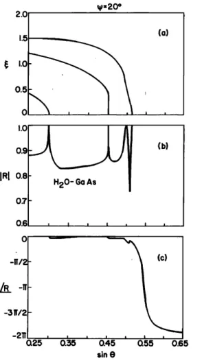
FIG. 3. Slowness surfaces (a) of GaAs for waves propagating in a plane oriented 20' with respect to a cube face. Reflectance function amplitude (b) and phase (c) at H20-GaAs (001) interface for the same incidence plane.
wave becomes evanescent as well. Here there is another pos- sibility that Rayleigh condition could be satisfied. The sec- ond transition indicates that there is indeed a Rayleigh wave excitation at sin 0• = 0.5545, and this wave is sometimes called a "generalized Rayleigh wave." For this wave the par- ticle motion is not in a plane normal to the surface. A surpris- ing fact to note is that the reflection coefficient is about 0.62 for 0.536 < sin 0r < 0.552.
The same set of curves is shown for •b = 20 ø in Fig. 3. For this case, there is only one trarrsition in the phase curve. Therefore the pseudo surface wave does not exist for this
orientation.
Actually
it has
been
shown
that
7 for the propa-
gation on the (001) plane of a cubic medium, the pseudo- surface wave is present only for a range of directions near I110] axis.To investigate the possibility of a null in the reflection coefficient several other orientation angles (•b) have been tried. The results are shown in Fig. 4. For •b = 25 ø the reflec- tion coefficient magnitude at sin O• = 0.53 is almost zero! The null in the reflection coefficient is not unique to H20- GaAs interface. Several other cubic crystals have been inves- tigated and they all have nulls albeit at different angles. Fig- ure 5 depicts the reflection coefficient for H20-InAs inter- face where the null is displayed for •b = 24 ø and sin 0•
.40 42 44 46 .45 50 Sin
H20-
Cu
t/'
... • =24.$ ø • =25.1 ø • =26 ø i i Sin eFIG. 4. Reflectance function amplitude for various orientations at H20-
GaAs interface.
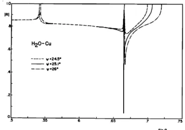
FIG. 6. Reflectance function amplitude for various orientations at H20-Cu
interface. Elastic parameters of Cu: c• = = 17.02X 101øN/m :, c44 = 7.51X 10•øN/m :, c•: ---- 12.3X 10•øN/m:, p = 8.936X 10³kg/m 3.
= 0.68. Figure 6 shows the results for H20-Cu interface. In this case a very narrow null is obtained around •b -- 25.1 ø and
sin 0 -- 0.665.
The
perfect
null
angle
can
be
found
by changing
•b
and
sin 0, appropriately using perhaps an iterative procedure. The null angle is in the region where only one QS wave can propagate in the cubic medium. Therefore at this angle there is a perfect power transfer from the incident wave in the liquid to a QS wave in the solid. We note that this impedance match occurs for a very narrow range of angle (in both 0, and •b directions).
To verify the validity of the program conservation of
energy
is checked
at each
angle.
Incident
power
is calculated
using normal component of the Poynting vector. This is compared with the sum of normal real components of Poynt- ing vectors for reflected and refracted waves. In the region of interest where only one QS wave can exist in the solid only the Poynting vector for this QS wave is real. Evanescent waves give rise to complex valued Poynting vectors.
H20-InAs ... y :22 ø • ¾=24 o y:26 ø •6 68 70 Sin e
FIG. 5. Reflectance function amplitude for various orientations at H20-
InAs interface. Elastic parameters of InAs: Cl• =8.329X10•øN/m :, c44 ---- 3.959X 10•øN/m:, c!: = 4.526X 10•øN/m:, p = 5.672X 10³kg/m 3.
III. DISCUSSION
To understand the reason why one may have an imped- ance match between a low-impedance liquid and a seemingly high-impedance anisotropic solid we shall look at a degener- •ate case, namely an isotropic solid. This case is so simple that
analytic expressions are available. The reflection coefficient
can be written as 4 + - Zo)/(z + + Zo), where
g 0 = (C0•O0)I/2/COS
0I,
g L = [(Cll•O)l/2/cos
0œ
]cos
2 20s
,
Z, = [(c44
p)l/2/cos
Os
] sin
2 20,,
with 0L and 0, being the refraction angles as determined by
the Snell's law
sin 0• sin 0L sin 0•
(Co/•O0)
1/2 (Cl
1/•O)
1/2 (C44/•O)
1/2
'
Making the analogy between the reflection process in acoustics with the reflection process in electrical transmis-
sion lines one has
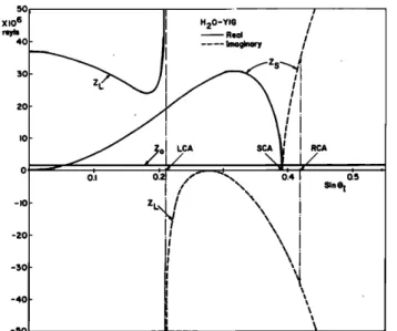
R = (Z]oad -- Zo)/{Z]oad + Zo), 'where Z]o•d = Z• + Zs. Z• is the impedance contribution of longitudinal waves and Zs is that of the shear waves. Contributions become imaginary when the corresponding wave becomes evanes- cent. Z•o•a and Zo for H20-YIG interface is plotted in Fig. 7. YIG is selected as the solid since it is very nearly isotropic.
Z• has a nonzero value at sin 0• -- 0 and approaches to infinity at the longitudinal critical angle (LCA). Beyond this angle Z• has a negative imaginary part. It vanishes when sin 0• = l/v/'2?. On the other hand Z• is zero at sin 0• = 0. It goes through a maximum and then it becomes zero at the
shear
britical
angle
(SCA).
For angles
exceeding
SCA,
Z, is a
monotonically increasing positive imaginary number. At an angle slightly above SCA, namely at the Rayleigh critical angle {RCA), ZL and Z• completely cancel each other while one is positive imaginary and the other is negative imagi-5O X 10 6 reyll 40 -I0 -2O -3O -4O -5O H20-YIG • Real ß ---- ImQginory
!I
IIFIG. 7. Zlo•d and Zo as a function of incidence angle for H20-YIG inter- face. Elastic parameters of YIG: c• -- 26.8 X 10mN/m 2, c•4 = 7.66X 10mN/m •, p -- 5.17X 10³kg/m 3.
nary. At this point Zlo•,d = 0 and it is the angle where a sur- face wave is excited. One should recall that for perfect match Z•oad = Zo must be satisfied. Since Zo is always positive real, a match can occur only in the region below LCA. But for most liquid-solid interfaces, this is not possible while the impedances of solids are usually much higher than that of liquids. {There are exceptions when liquid is a heavy metal like mercury or gallium.}
Using the results of isotropic case we propose to write the reflection coefficient for a liquid-anisotropic solid inter-
face as
R = (Zload -- Z0)/(Zload -[-- Z0) , and Zload = Z L -• Z$1-• Z$2 , •
where Z L, Zs•, and Zs2 are the impedance contributions of QL and two QS waves, respectively. Although we do not have analytic expressions for these impedances we expect that they behave similarly to those of the isotropic case. But
overall behavior should be different since there are three
critical angles as opposed to two. Each contribution will be- come imaginary when the corresponding critical angle is ex-
ceeded.
There are four distinct regions separated by the three critical angles. In region I [below the quasilongitudinal criti- cal angle (QLCA)] ZL, Zs•, and Zs2 are all positive real. In region II where QLCA is exceeded Z• becomes negative imaginary while Z s • and Z s• are still positive real. In region III, the first QS critical angle (QSCA1) is exceeded and Zs• becomes positive imaginary. In this region (between QSCA 1 and QSCA2) Zs• and Z• are imaginary with opposite signs while Zs• is positive real. One may expect a cancellation of Zsl and Z• at some angle similar to that which occurred in the isotropic case under Rayleigh critical angle excitation. If this angle exists it will be the pseudo-surface .wave angle (PSWA). At this angle Zload is equal to Zs• and it is positive real. In region IV where all critical angles are exceeded all three contributions to Z•oad are imaginary. For some cases there may be a fifth region within region II. In this range three QS waves are excited; therefore Zload is real again even though QLCA is exceeded. The statements in this paragraph
are summarized in Table I.
For an impedance match to occur Zload must be equal to Z o. Recall that Z o is always positive real. Therefore a match may occur only if Zload is positive real. This is satisfied in region I, in region IlI at PSWA, and in region V if it exists. For most liquid-solid interfaces a match cannot occur in region I since Zt is much higher than Zo. Similarly region V is an unlikely region for a match for Zload has three positive real (possibly large) components in this region. On the other
TABLE I. Expected behavior of ZL, Zs •, and Zs2 as a function of incidence angle.
Incidence angle Region ZL Zs • Zs2
Zload --- Z 0 Zload -'- Zo Z lead possible? likely? positive 0 real positive yes real no 0• < QLCA I positive real positive positive real real positive yes real no
QLCA < 0• < QSCA1 II negative imag QSCA1 - e < 0• < QSCA1
positive positive
real real
V positive positive positive
if exists real real real
no
complex (unless no
positive yes
real
no
QSCA1 < 0• < QSCA2 III negative imag
positive positive imag real
complex no no
0• = PSWA III negative imag
positive positive imag( ---- -- Z•) real
positive yes yes
real 0• > QSCA2 IV negative imag positive positive imag imag imaginary no ß no
hand at PSWA in region IIIa match may be possible. If Zs,• = Zo is satisfied, all the incident power will be coupled to a QS wave inside the solid. Unfortunately we do not have an analytic expression for Zs,•. Its value should depend on sin 0, as well as the orientation angle •. We assume that it behaves like Zs of isotropic case (as shown in Fig. 7). With this assumption one may argue that Zs,• = Zo will be satis- fied for some 0, = 0½ at any given orientation angle •, be- cause the corresponding curves in isotropic case intersect each other (see Fig. 7). A match condition will be achieved if 0½ coincides with PSWA. This coincidence--if it occursin will take place at a particular orientation •½. Therefore a null in the reflection coefficient will be seen if Zs2 = Zo is satis-
fied at a pseudo-surface
wave
angle.
8 On the other hand if
Zs,• = Zo is satisfied at an orientation where there exists no pseudo-surface waves, a null will not be present.The heuristic argument above does not guarantee that there is an angle of perfect match for every liquid-cubic- solid interface. It merely shows that ifa pseudo-surface wave exists, a perfect coupling from the incident longitudinal wave in the liquid to a QS wave in the solid might occur for some orientation •½.
The conclusions reached above could be generalized to other faces of cubic crystals and to any face of any anisotro- pic solid for we have not used cubic symmetry in the argu- ments. Therefore one may expect to find reflection coeffi- cient nulls for any anisotropic medium as long as pseudo-surface waves exist on the surface of interest.
IV. CONCLUSION
The results of numerical calculations for the reflection
eoeftieient at a liquid-cubic-solid interface are presented. The calculations are performed only for the (001) face of the
solid. A null in the reflection eoeftieient is &teeted for a
particular orientation. At this angle all the incident power in the liquid is coupled into a quasishear wave in the solid. Various computer runs showed that this is not unique to certain materials. An explanation is presented for the pres- ence of null in the reflection eoefticient using an impedance argument. This argument shows that if there is a null in the reflection eoeftieient it will be at an angle associated with the pseudo-surface wave. The same argument concludes that this null is not unique to the (001) face of cubic materials; other materials with noncubic symmetry might have nulls in
the reflection eoeftieient as well.
•F. L. Becker and R. L. Richardson, J. Acoust. Sac. Am. 51, 1609 (1972). •M. A. Breazeale• L. Adler, and G. W. Scott, J. Appl. Phys. 48, 530 (1977). 3T. J. Plona, M. Behravesh, and W. G. Mayer, J. Acoust. Sac. Am. 56, 1773
(1974).
nL. M. Brekhovskikh, Waves in Layered Media (Academic, New York,
1960).
SB. A. Auld, ,•coustic Fields and Waves in Solids, Vols. 1 and 2 (Wiley-
Interscience, New York, 1973).
6E. •. Henneke, II, J. Acoust. Soc. Am. 51, 210 (1972).
?T. C. Lira and G. W. Farnell, J. Acoust. Sac. Am. 45, 845 (1969). 8F. R. Rollins, T. C. Lira, and G. W. Farnell, Appl. Phys. Lett. 12, 236
(1968) calculated the pseudo-surface velocities for (100) face of copper. The velocity at • = 25.1 ø agrees very well with the null angle shown in Fig. 6.