EFFECT OF HEIGHT ON THE STATIC STABILITY OF HETEROGENEOUS EMBANKMENT DAMS
1Mohsen YAZDANIAN,*, 2Hamid Reza AFSHOON, 3Sadegh GHASEMI, 4Vahid AFSHOON,
5Farhad FAHIM
1, 2, 3, 5 Young Researchers and Elite Club, Ahvaz Branch, Islamic Azad University, Ahvaz, Iran 4M.Sc student, Department of Civil Engineering, Yasooj Branch, Islamic Azad University, Yasooj, Iran
1[email protected],2[email protected],3[email protected], 4[email protected], 5[email protected]
(Geliş/Received: 23.03.2016; Kabul/Accepted in Revised Form: 03.05.2016)
ABSTRACT: The main objective in designing an embankment dam is to achieve a structure that keeps water and in addition prevents seepage in downstream that has piping and rupture. Therefore, the present study examined the effect of height on upstream and downstream slope stability of heterogeneous embankment dams with the same characteristics but with different heights at the end of construction and Steady-State Seepage and Rapid Drawdown. To investigate the effects of height, two dams with a height of 62 meters and 133 meters and 6 meters crest width were modeled in Geostudio software. The embankment dam is composed of 14 different areas with different characteristics. To analyze the dam stability, SLOP/W and to model the movement of water in dam due to presence of water behind the dam in a Rapid Drawdown and Steady -State, seepage SEEP/W in Geostudio was used. Finally, the obtained safety factors in two dams with different height are compared with each other and the obtained safety factor was compared with USBR safety factor. This research showed that the safety factor is safer for 62 meters dam. The safety factor in shorter dam is safer than long dam.
Key Words: Embankment dam, Height, Geostudio, Slope/w, Stability analysis,
Hetorojen Embankment Barajların Statik Stabilisezi Üzerinde Yüksekliğin Etkisi
ÖZ: Bir dolgu baraj tasarımında temel amaç suyu tutan bir yapı elde etmektir ve buna ek olarak b oru ve yırtılması olduğu mansabında sızıntı önler. Bu nedenle, bu çalışmada inşaat ve-Kararlı Hal Sızma ve hızlı Drawdown sonunda aynı özelliklere sahip heterojen dolgu barajların memba ve mansap şev stabilitesi üzerine ancak farklı yükseklikleri ile yüksekliğinin etkisi incelenmiştir. yüksekliği etkilerini araştırmak amacıyla, 62 metre ve 133 metre 6 metre kret genişliği yüksekliğinde iki baraj Geostudio yazılımında modellenmiştir. su bendi, farklı özelliklere sahip 14 farklı alanlardan oluşmaktadır. Yansımalar SLOP/W , baraj kararlılığını analiz etmek ve nedeniyle hızlı Drawdown ve Sabit -Devlet baraj arkasında suyun varlığına baraj su hareketini model, Geostudio içinde sızıntı SEEP / W kullanıldı. Son olarak, farklı yüksekliğe sahip iki baraj elde edilen güvenlik faktörleri birbirleriyle karşılaştırılmış ve elde edilen güvenlik faktörü USBR emniyet faktörü ile karşılaştırıldı. Bu araştırma emniyet faktörü 62 metre baraj için daha güvenli olduğunu göstermiştir. kısa baraj emniyet faktörü uzun baraj daha güvenlidir.
Anahtar Kelimeler: Su bendi, Yükseklik, Geostudio, Slope/w, Stabilite analizi,
INTRODUCTION
Embankments are made up of unsaturated compacted soils and their behaviour is strongly affected by the climatic or environmental perturbations (Cui et al., 2010; and Maharjan and Takahashi, 2014) Understanding of the structural deformation performance can be causes to design structures in a safety situation. Design and construction of structures must be including the environmental protection, the preservation of structures during natural accidents and also construction costs (Gikas and Sakellariou, 2008).
Dams are type of structures constructed against stream, river, or waterway for the purpose of restrict and controlling the move of water. A dam is constructed for particular duty such as water storage; irrigation; flood controlling and also dams are used for yield hydroelectric power (Ismail et al., 2012; Novak et al., 2001). There are two types of modern dam namely embankment dam a nd concrete dam.
One of the most important subjects of concern in Geotechnical and structural engineering for embankment dam is Slope stability. Slope stability analysis of earthen dam is dependent to many parameters which must consider in design and construction. Stability of these structures is composed of many ambiguities relevant to lack of precise geotechnical parameters. Because of the importance of dam construction and its related expenses, determination of dam behavior has an important result for makers. By considering the uncertainties of geotechnical parameters, applying risk analysis is unavoidable in dam construction (Manafi Ghorabaei et al., 2012).
Investigating of slope stability of earthen dam slopes is an advanced procedure which has been shown to lead to a more economical design by many researchers like (Banaki et al., 2013) which states that the cases that computed safety factor without modeling uncertainties is more than reality value. These methods do not consider many uncertainties in th eir computations. Also, many conservative factor of safety are using to cover some uncertainties which in most cases are more than required, and in some cases less than amount that is necessary. Actually, it is not possible to recognize the accurate effect of these factors of safety on safety level (Manafi Ghorabaei and Noorzad, 2011).
Numerical simulation methods is a good method that usually lead to make easier the real behavior of structure and widely applied in last decades. The numerical analysis is al so able to simulate the behavior and any possible damage pattern of a dam (Sakamoto et al., 2002). Dams should be designed and constructed from available materials in any place that possible usually dams are constructed from material which are near to location of work due to Dams required many materials and this will not be economical to carry this material from places which are far from the location. The dams should stay stable and showed suitable and useful performance under all conditions, during constru ction, and ultimately in operation, both at the normal reservoir operating level and under all flood and dry conditions. Also, the dam and foundation should be having suitable behavior across to manage seepage and manage the suitable reservoir level (Ratnayaka et al., 2009). Considering the items mentioned above and knowing that dams are structures which disruption and deterioration can cause irreparable financial and physical damages, analysis of stability of embankment dams are of utmost importance. In this study, dam static stability was examined using Geostudio (Geostudio, 2007) in different modes and safety factor obtained for both cases.
MATERIALS AND METHODS
In this research, the stability of the upstream and downstream slopes of the dam embankment is performed for the most critical or severe loading conditions that may take place along the life of the dam as follow (USSD, 2007).
1) End of Construction — when significant pore pressure development is expected either in the embankment or foundation dur ing construction of the embankment.
2) Steady-State Seepage — when the long-term phreatic surface within the embankment has been established.
3) Rapid (or Sudden) Drawdown — when the reservoir is drawn down faster than the pore pressures can dissipate within the embankment after the establishment of steady -state seepage conditions.
In this paper, Geostudio (Geostudio, 2007) is used to model two embankment dams. To study the effects of height, two dams with a height of 62 and 133 meters and 6 meters crest width were modeled in Geostudio. To analyze the dam stability, SLOP/W (2007) and to model the movement of water in the dam to analyze steady-state seepage condition, SEEP/W (2007) were used. One of the capabilities of SEEP/W is to plot the balance passing the soil and velocity vectors and drawing the flow lines and potential as well as calculating the discharge for a certain level of water. Also in Rapid Drawdown, it is assumed that the balance of the reservoir water has dropped by 60 percent, for this purpose, the 60 percent is multiplied in the height of the reservoir water in the Steady -State seepage mode to obtain the water drop then by subtracting the amount of the total height of the reservoir, the water height after drop is achieved. In this case, the materials are assumed to be consolidated and undrained (CU). In modeling, both embankment dams are modeled with the same materials. Also both embankment dams are composed of 14 different areas with different characteristics. In table 1 the properties of material is expressed. Mohr-Coulomb method, the most common way of defining the shear strength of geotechnical materials is used in current research.
Table 1. Characteristics of materials
Material ( 3) m t ( 3) m t sat
c ( ) 2 m t Clay core Zone1(UU) 2 2.06 10 10 Zone1(CU) 2 2.06 20 5 Zone1(CD) 2 2.06 28 0 Upstream section Zone 2 2.1 2.2 43 0 Zone 3 2.1 2.2 41 0 Zone 4 2.1 2.2 39 0 Zone 5 2.1 2.2 38 0 Zone 6 2.1 2.2 37 0 Downstream section Zone 7 2.1 2.2 41 0 Zone 8 2.1 2.2 39 0 Zone 9 2.1 2.2 37 0 Zone 10 2.1 2.2 36 0 Depth 0-20 m Zone 11 Depth 0-20 m Zone 11 2.6 2.65 35 30 Depth 20-100 m zone 12 2.6 2.65 55 35 Mudstone Zone 13 2 2.1 25 10 Conglomerate, mud stone Zone 14 2 2.1 24 20 FACTOR OF SAFETYConventional analysis methods characterize the stability of a slope by computing a safety factor. The safety factor is clarified with respect to the shear strength of the soil as the ratio of the a vailable shear strength (s) to the shear strength required for equilibrium as follow (US Army Corps of Engineers, 2003).
s stress shear m Equilibriu strength shear Avaliable F (1)If the shear strength is defined in terms of effective stresses, the safety factor is indicated as follow (US Army Corps of Engineers, 2003).
c ( u)tan F (2) where c , are Mohr-Coulomb cohesion and friction angle, respectively, expressed in terms of effective stresses; is total normal stress on the failure plane; u is pore water pressure; (u) is the effective normal stress on the failure plane. If the failure envelope is curved, the safety factor can be stated as follow follow (US Army Corps of Engineers, 2003).
) (
s
F (3)
Where s( ) characterizes the shear strength determined from the effective stress failure envelope for the particular effective normal stress,
. Eq 2 can be utilized with a curved failure envelope by letting c and characterize the intercept and slope of an equivalent linear Mohr -Coulomb envelope that is tangent to the curved failure envelope at the proper amount of normal stress,
. For total stresses, the safety factor is stated using the shear strength parameters in terms of total stresses, as follow (Spencer, 1967 and USBR, 2011).
c tan F (4)Wherec ,
are the Mohr-Coulomb cohesion and friction angle, respectively, are expressed in terms of total stresses. For analysis of Embankment dams, Morgenstern -Price (Morgenstern and Price, 1965) method is used. Morgenstern and Price (1965) developed a method similar to the Spencer (Spencer, 1967) Method, but they allowed for various user -specified interslice force functions. This method Considers both shear and normal interslice forces, Satisfies both moment and force equilibrium, and also allows for a variety of user-selected interslice force function.RESULT AND DISCUSSION
Embankment dams during construction and operation are exposed to a variety of stresses that should be designed and implemented safe to withstand these stresses. Different researchers and engineers have already introduced various methods to analyze the stability of the slope of the embankment or rock-fill dam that can be divided into two general methods: limiting equilibrium and stress-strain. The basis of limiting equilibrium methods is on determining the imposed stress and mobilized resistance in a hypothetical fractured surface in embankment slope and then determining the safety factor given the ratio of these two quantities. In stress – deformation method, stresses and strains caused by dam in different parts of the body and foundation of embankment dam are analyzed and according to it, while preparing a picture of the behavior of the dam, safety factor on the most potential rupture surface is determined by comparing the mobilized shear strength in the surface. In examining the stability of embankment dams, forces that cause slope instability include: gravity and leakage. Given that the basic calculations are based on effective stress need to know the pore pressure, therefore, to design three critical steps should be considered: 1) the end of construction, which is affected by the compression due to the increased height of the embankment. 2) Steady-State seepage which occurs after filling the dam reservoir and passing enough time. 3) Rapid Drawdown of the reservoir, which occurs during or after the lowering of the water level in the reservoir after establishment of Steady -State seepage condition.
End of Construction Loading Condition
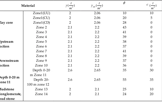
End of Construction phase has always higher safety factor than other phases, prior to the start of catchment, due to the reduction of pore water pressure distribution. In this case, the stability of the dam should be examined in the case of effective stress and total stress. For effective stress analyses, pore water pressures must be defined and their values must be specified. For total stress analyses using computer program, hand calculation, or slope stability charts, pore water pressures are defined as zero, actually, the pore pressures are not equal zero. This is essential because of all computer programs for slope stability analyses subtract pore pressure from the total normal stress at the base of the slice [12]. In end of the construction condition, both dow nstream and upstream slope of the embankment dam is in critical condition. In this case, the materials used in the clay core are undrained and unconsolidated (UU). In the effective stress space, pore water pressure is dedicated for the core. The core is also divided into some parts. To allocate these coefficients to the core, 8 identical materials are defined for the core. For these materials, according to the figure 1 values of Ru are defined and Ru related to each part is assigned to the appropriate section. Also in the total stress, the core is considered without pore water pressure. According to the obtained values, it was observed that in both dams, resulting safety factors in upstream are safer than safety factors in downstream.
Figure 1. The values of pore water pressure Ru at the end of construction
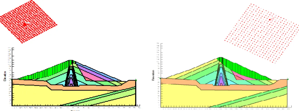
Figure 2. Analysis in effective stress space for upstream and downstream of the dam with a height of 62 meters.
Figure 3. Analysis in effective stress space for upstream and downstream of the dam with a height of 133 meters.
Steady-State Seepage Loading Condition
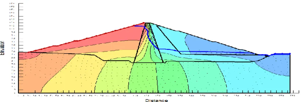
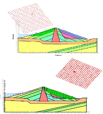
After the construction of the dam and passage of the time required, Steady -State seepage condition will be established in dam body and foundation and over time the consolidation will take place in dam body. So the stability of upstream and downstream slope should be analyzed based on effecti ve stress analysis. The basic equation of groundwater motion is obtained as two-dimensional under conditions of saturated and unsaturated flow by combining the Darcy's law and continuity equation. In Steady-State seepage condition, the upstream and downstr eam of dam is analyzed after the dam catchment and the stability safety factor will be controlled. Steady-state seepage loading condition should be performed using effective stress shear strength parameters joined with measured or estimated embankment and foundation pore pressures. The use of the CD triaxial shear test is appropriate for this phase (USBR, 2011). In Steady-state seepage conditions, first it should be determined the reservoir level that controls development of the steady-state phreatic surface .Since the embankment dam in most of its lifetime is in Steady-State seepage, and then it needed high safety factor. In this part, pore water pressure condition is not defined by Ru. In this case, it needed to draw phreatic line for the dam and to this end; it is performed by using SEEP/W of the software. One of the special features of this software is the possibility of modeling the condition of half-saturated soil that affect the permeability. The materials used in clay core are examined in consolidation and drained (CD) mode to let the materials to be fully consolidated and also to have the opportunity for drainage. In this analysis, after the points are extracted from SEEP/W, the extracted points are drawn in SLOP/W. in figure 4 the phreatic line obtained from SEEP/W is displayed for a dam with a height of 62 meters. Figure 5 is shown the Steady -State seepage analysis in upstream and downstream for a dam with a height of 133 meters.
Figure 5. Steady-State seepage analysis in upstream and downstream for a dam with a height of 133 meters.
Rapid Drawdown Loading Condition
If the water level behind the dam can be lowered, the seepage in the dam body will change and seepage line will be reversed. That's why the study of upstream slope against rapid Drawdown is important. The reservoir rapid Drawdown can cause instability and incidence slip in the upstream slope which results is remaining the dam materials in saturation and starting the leakage flow towards upstream slope. If the reservoir discharge is done at a rate that in time of drop in water level, the pore water pressure inside the body is not changed and phreatic line remains in its previous position, this process is called reservoir rapid Drawdown. In the rapid Drawdown of reservoirs, sharp reduction of the pore water pressure will be created and with sharp and abrupt decrease in pore pressure, the pressure imposed to the on the dam body will increase and cause rupture in the dam body. The use of the CU triaxial shear test is appropriate for rapid drawdown condition (USBR, 2011). Tran (2004) by studying the phenomenon of rapid Drawdown in the dam reservoir concluded that with water level drops to one-third of the height of dam, confidence level decreases to a considerable amount. His studies showed that safety factor of upstream slope stability is reduced to 34% for the water level to drop for a third of the height of the dam, and the amount for the com plete discharge of the reservoir is 43 percent. In rapid Drawdown , it is assumed that the reservoir level has dropped 60 percent, to this end, 60 percent is multiplied in the height of the water reservoir to obtain the water depression, then by subtracting the amount of the total height of the reservoir, the water level after loss will be obtained. In this case, materials are assumed as undrained and consolidated (CU). In Table 2 the overall results obtained for the safety factors in different states are presented, these values are obtained by performing a lot of analysis on dams.
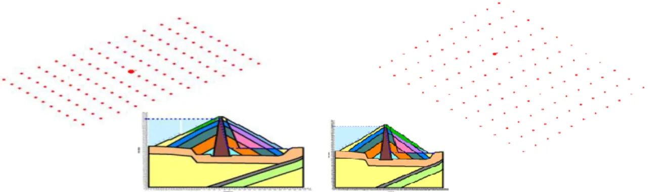
Figure 6. Rapid Drawdown analysis in upstream and downstream of dam with a height of 62 meters.
Table 2. safety factors presented in different modes
133(m) 62(m) Loading condition upstream downstream upstream downstream 1.264 0.986 2.227 1.823 End of Construction (
) 1.247 0.998 2.189 1.825 End of Construction (
) 1.166 0.994 2.125 1.801 Steady-State Seepage 0.967 0.979 1.359 1.78 Rapid Drawdown CONCLUSIONIn this study, two dams with the completely identical characteristics and different heights were modelled using software and the effects of height on the obtained safety factor were studied. In the state of end of construction, for dams with different heights, the effective stress and the total stress of the upstream slope is more stable than downstream slope. Comparing the safety factor, it is clearly seen that the safety factor in shorter dam is safer than the higher dam. Also the value of safety factor obtained from the minimum value of USBR, which is 1.3, is more for shorter dam, which is concluded that the shorter dam is stable in this case. In case of steady-state seepage of the dam upstream slope is more stable than the downstream slope and by comparing with the value of USBR which is 1.5, it is determined that the safety factor is safer for 62-meters dam. In this case, the safety factor in shorter dam is safer than long dam. In the case of the rapid Drawdown due t o change for upstream phreatic surface, and inversing the direction of seepage, pore water pressure distribution changes and seepage force may cause instability of the slope and threatens the upstream slope and it should be used proper filter and drainage for the dam. In this case, the safety factor in shorter dam is safer than the higher one. In this case, the minimum USBR value is 1.3, and then the safety factor value should be higher than the amount that for 62-meters dam it is the same, although the use of filters and drainage for upstream dam for reassuring is necessary. With an overall review of the study, it was determined that by increasing the height, dam stability and safety factors will be reduced for stability.
REFERENCES
Banaki, R., Ahmad, F., Tabarroki M., Yahaya A.S., 2013, “Probabilistic Analyses of Slopes: A State of the Art”, International Journal of Current Engineering and Technology, Vol. 3(1), pp. 58 -63. Cui, Y. J., Gao, Y. B., Ferber, V., 2010, “Simulating the Water Content and Temper ature Changes in an
Experimental Embankment Using Meteorological Data”, Engineering Geology, Vol. 114(3), pp. 456-471.
Gikas, V., Sakellariou M., 2008. “Settlement Analysis of The Mornos Earth Dam (Greece): Evidence from Numerical Modeling and Geodetic Monitoring”, Engineering Structures, Vol. 30(11), pp. 3074 – 3081.
Ismail, M.A.M, Ng, S. M, Gey, E.K., 2012, “Stability Analysis of Kelau Earth-Fill Dam Design under Main Critical Conditions”, The Electronic Journal of Geotechnical Engineering, Vol. 17
Maharjan, M., Takahashi, A., 2014, “Liquefaction-Induced Deformation of Earthen Embankments on Non-Homogeneous Soil Deposits Under Sequential Ground Motions”, Soil Dynamics and Earthquake Engineering, Vol. 66, pp. 113-124.
Manafi Ghorabaei S.M, Noorzad, A., Mahdavifar, M., Soleimannejad, A., 2012, “Risk Analysis of the Slope Stability of Embankment Dam Using Three Different Approaches”, 6th International Symposium on Advances In Science and Technology, Kuala Lumpur, Malay sia, 24-25 March, 2012.
Manafi Ghorabaei, S M, Noorzad, A, 2011. “Role of Risk Assessment in Repair an d Rehabilitation of Earth Dams”, Proceedings of the National Workshop on Operation, Maintenance and Rehabilitation of Dams and Hydropower Plants, Tehran, Iran: Iranian National Committee on Large Dams (IRCOLD).
Morgenstern, N.R., Price, V.E., 1965, “The Analysis of the Stability of General Slip Surface” Geotechnique, Vol. 15, pp. 79-93.
Novak, P., Moffat, A.I.B., Nalluri, C., Narayanan, R., 2001, Hydraulic Structures Fourth Edition, Taylor & Francis Group, London.
Ratnayaka, D.D., Brandt, M.J., Johnson, M., 2009, Twort's Water Supply 6th Edition, Butterworth -Heinemann: Elsevier.
Sakamoto, T., Yoshida, H., Yamaguchi, Y., Satoh, H., Tomoya, I., 2002, “Numeri cal Simulation of Sliding of An Earth Dam During The 1995 Kobe Earthquake” in Proceedings of the 22nd USSD Annual Meeting and Conference, Pre-conference Workshop, 3rd U.S.Japan Workshop on Advanced Research on Earthquake Engineering for Dams, San Diego, Ca lifornia, 26-31 March 2001.
Seepage Modeling with SEEP/W, 2007, An Engineering Methodology Third Edition, March 2008 , GEO-SLOPE International Ltd., Canada.
Spencer E, 1967, “A Method of Analysis of The Stability of Embankments assuming Parallel Interslice Forces”, Geotechnique, Vol 17 (1), pp. 11-26.
Stability Modeling with SLOPE/W, 2007, An Engineering Methodology Third Edition, March 2008 , GEO-SLOPE International Ltd
Tran, T.X., 2004, Stability problems of An Earth Fill Dam in Rapid Drawdown Condition, Doctoral dissertation Slovak University of Technology, Bratislava, Slovak Republic.
United States Society on Dams, 2007, Strength of Materials for Embankment Dams, Denver, USA: US Society on Dams.
US Army Corps of Engineers, 2003, Engineering and Design - Slope Stability, Washington DC, USA: US Army Corps of Engineers.
USBR, 2011, Design standard No. 13, Embankment Dams, Chapter 4: Static Stability Analysis, U.S, Department of the Interior, Bureau of Reclamation.