İZMİR KATİP ÇELEBİ UNIVERSITY GRADUATE SCHOOL OF SCIENCE AND ENGINEERING
DESIGN OF WIRELESS CONTROLLED ROBOTIC HAND
M.Sc. THESIS
Faruk Sanberk KIZILTAŞ
Department of Biomedical Technologies
Thesis Advisors: Assist. Prof. Dr. FatihCemal CAN Assist. Prof. Dr. Erkin GEZGİN
İZMİR KATİP ÇELEBİ UNIVERSITY GRADUATE SCHOOL OF SCIENCE AND ENGINEERING
DESIGN OF WIRELESS CONTROLLED ROBOTIC HAND
M.Sc. THESIS
Faruk Sanberk KIZILTAŞ (Y140101001)
Department of Biomedical Technologies
Thesis Advisors: Assist. Prof. Dr. FatihCemal CAN Assist. Prof. Dr. Erkin GEZGİN
İZMİR KATİP ÇELEBİ ÜNİVERSİTESİ FEN BİLİMLERİ ENSTİTÜSÜ
KABLOSUZ KONTROL EDİLEBİLEN ROBOTİK EL TASARIMI
YÜKSEK LİSANS TEZİ Faruk Sanberk KIZILTAŞ
(Y140101001)
Biyomedikal Teknolojiler Anabilim Dalı
Tez Danışmanları: Yrd. Doç. Dr. Fatih Cemal CAN Yrd. Doç. Dr. Erkin GEZGİN
v
Faruk Sanberk KIZILTAŞ, a M.Sc. student of İzmir Katip Çelebi University Graduate School of Science and Engineering student ID Y140101001, successfully defended the thesis entitled “DESIGN OF WIRELESS CONTROLLED ROBOTIC HAND” which he prepared after fulfilling the requirements specified in the associated legislations, before the jury whose signatures are below.
Date of Submission: 01 December 2017 Date of Defense : 22 December 2017
Thesis Advisor : Assist. Prof. Dr. FatihCemal CAN ... İzmir Katip Çelebi University
Thesis Co - Advisor : Assist Prof. Dr. Erkin GEZGİN ... İzmir Katip Çelebi University
Jury Members : Assoc. Prof. Dr. Gökhan KİPER ... İzmir Institute of Technology
Assist. Prof. Dr. Özgün BAŞER ... İzmir Katip Çelebi University
Assist. Prof. Dr. Savaş ŞAHİN ... İzmir Katip Çelebi University
vii
ix FOREWORD
Firstly, I would like to thank to my supervisors Assist. Prof. Dr. Fatih Cemal CAN and Assist. Prof. Dr. Erkin GEZGİN who shared their valuable information with me. Whenever I consult them, they spared their precious time and helped me with patience. I am also grateful to Mustafa Volkan YAZICI for helping me to connect and print mechanical parts of robotic hand.
I also would like to thank to Hacer TÜRETKEN to help me for sewing flexible sensors on gloves.
I am too much grateful to Gökçenur TÜRETKEN for being too much patient with me and supporting me.
I also would like to thank my dear Uncle Orhan KIZILTAŞ and Aunt Zeynep KIZILTAŞ to opening their doors during my study.
Finally, I would like to thank to my parents who raised and supported me until today. I know when I need help you will support me.
xi
TABLE OF CONTENTS
FOREWORD ... ix
ABBREVIATIONS ... xiii
LIST OF TABLES ... xv
LIST OF FIGURES ... xvii
SUMMARY ... xix ÖZET ... xxi 1. INTRODUCTION ... 1 1.1 Robotic Hands ... 2 1.2 Prosthesis Hands ... 7 1.3 Wireless Communication ... 11
1.4 Aim of the Study ... 13
2. DEGREES OF FREEDOM AND ANATOMY OF HUMAN HAND ... 15
2.1 Forearm ... 15
2.2 Bones of human hand and degrees of freedom ... 15
3. STANDARDS AND CONFIGURATION OF ELECTRONIC COMPONENTS ... 19
3.1 Standard Of IEEE 802.15.4 And Zigbee Protocol ... 19
3.1.1 Standard of IEEE 802.15.4 ... 19
3.1.2 Zigbee ... 20
3.2 Zigbee Device Types And Network Topologies ... 21
3.2.1 Zigbee device types ... 21
3.2.2 Zigbee network topologies ... 22
3.3 Xbees And Configuration Of Xbees By Using X-CTU ... 23
3.3.1 XBee ... 23
3.3.2 Configuration of xbees by using X-CTU ... 27
3.3.2.1 Channel ... 27
3.3.2.2 Pan adress ... 27
3.3.2.3 My adress ... 27
3.3.2.4 Destination adress ... 28
4. DESIGN AND MANUFACTURING OF ROBOTIC HAND ... 29
4.1 Design Criteria and Component Descriptions ... 29
4.2 Designing and Manufacturing of the Robotic Hand ... 29
4.2.1 Finger and hand sizes ... 30
4.2.2 Tendon – wire systems ... 31
4.2.3 Kinematic analysis of fingers ... 35
4.2.4 Working Area of fingers ... 37
4.2.5 Inverse kinematic analysis of fingers ... 43
4.2.6 Controlling of robotic hand ... 44
5. CHARACTERIZATION AND CALIBRATIONS OF SENSORS ... 47
6. PROGRAMMING THE ROBOTIC HAND ... 65
6.1 Arduino ... 65
6.1.1 Arduino mega ... 65
6.2 The Used Programming Software ... 66
xii 8. EXPERIMENTS... 71 9. CONCLUSION ... 75 REFERENCES ... 77 APPENDICES ... 81 APPENDIX A ... 82 APPENDIX B ... 83 APPENDIX C ... 84 APPENDIX D ... 85 APPENDIX E ... 91 CURRICULUM VITAE ... 95
xiii ABBREVIATIONS
MCP : Metacarpal Phalanx DIP : Distal Interphalanx
PIP : Proximal Interphalanx Joints DoF : Degrees of Freedom
FE : Flexion / Extension AA : Abduction / Adduction CMB : Carpal Metacarpal Bones PWM : Pulse Width Modulation
PAN ID : Personal Area Network Identifier WPAN : Wireless Personal Area Network
CH : Channel
DL : Destination Low Address MY : 16-bit source Address AT : Transparent Mode
API : Application Programming Interface
BD : Baud Rate
BT : Bluetooth
CSMA / CA : Carrier Sense Multiple Access / Collision Avoidance BPSK : Binary Phase Shift Keying
xv LIST OF TABLES
Table 1.1 : Developed robotic hands ... 7
Table 1.2 : Prosthesis hands for commercial purposes (general characteristics)[19] 10 Table 1.3 : Prosthesis hands for commercial purposes (kinematic haracteristics)[19] ... 11
Table 2.1 :Degrees of freeedom of human hand ... 18
Table 3.1 :Comparison of LR – WPAN with other wireless networks [41] ... 19
Table 3.2 :IEEE 802.15.4 High Level Characteristics [41] ... 20
Table 3.3 :Wireless Communication Networks [42,52] ... 21
Table 3.4 :Comparison of ZigBee Devices [50]. ... 22
Table 3.5 :XBee S1 versus XBee S2 [43] ... 24
Table 3.6 :Pins of XBee S2[43] ... 26
Table 3.7 :XBee configurations. ... 28
Table 4.1 :Finger sizes in length and thickness ... 31
Table 4.2 : Denavit – Hartenberg parameters ... 35
Table 4.3 : Some finger movements of robotic hand. ... 42
Table 5.1 :Analog output values of flexible sensor ... 48
Table 5.2 :Formula and graphic according to flat position ... 49
Table 5.3 :Analog output values of flexible sensor according to graphs ... 50
Table 5.4 :Formula and graphic according to 𝑦 = 𝑥2 equation ... 51
Table 5.5 :Formula and graphic according to 𝑦 = 𝑥3 + 2𝑥2 + 3 equation ... 52
Table 5.6 :Measurement results of every 10 degree... 52
Table 5.7 :Formulas and graphics for every 10 degree angle ... 53
Table 5.8 :Measurement results of the equation 𝑦 = 𝑥2/25 ... 55
Table 5.9 : Measurement results of the equation 𝑦 = 𝑥2 ... 55
Table 5.10 : Formulas and graphics according to 𝑦 = 𝑥2/25 and 𝑦 = 𝑥2equations 56 Table 5.11 : Measurement results of the equation𝑦 =𝑥2 8 ... 59
Table 5.12 : Measurement results of the equation 𝑦 =𝑥2 16 ... 59
Table 5.13 : Formulas and graphics according to 𝑦 = 𝑥2/8 and 𝑦 = 𝑥2/16 equations ... 60
Table 7.1 :Electrical components on Arduino Mega 2560 (Transmitter).. ... 67
Table 7.2 :Electrical components on Arduino Mega 2560 (Receiver).. ... 68
xvii LIST OF FIGURES
Page
Figure 1.1 : Designed by Leonard Aydt [3] ... 2
Figure 1.2 : Designed by Louis G. Caron [4]... 3
Figure 1.3 : Designed by James F. Mullen [5] ... 3
Figure 1.4 : Designed by UTAH / MIT [6] ... 4
Figure 1.5 : Designed by Carl F. Ruoff [7] ... 5
Figure 1.6 : Designed by Gaiser et al [8] ... 5
Figure 1.7 : Designed by Mouri et al [9]... 6
Figure 1.8 : Designed by Yamano and Maeno [10] ... 6
Figure 1.9 : Designed by Thedore Opuszenski [15] ... 8
Figure 1.10 : Designed by Robinson George B [16]... 8
Figure 1.11 : Designed by George T. Pinson [17] ... 9
Figure 2.1a :Muscles on the forearm from bottom side [45] ... 15
Figure 2.1b :Muscles on the forearm from top side [46] ... 15
Figure 2.2 :Metacarpal joint motions (adduction and abduction,flexion, extension) [49] ... 16
Figure 2.3a :Anatomy of Human Hand Bones [47] ... 17
Figure 2.3b : Anatomy of Human Hand Joints [48] ... 17
Figure 3.1 : Zigbee network topology [43] ... 22
Figure 3.2 :XBee usb adapter ... 25
Figure 3.3 :XBee breakout board ... 25
Figure 3.4 :X-CTU ... 27
Figure 3.5 :Venn diagram of XBee network [43] ... 28
Figure 4.1 :Index finger ... 30
Figure 4.2 :Palm sizes (mm) ... 31
Figure 4.3a : Tendon – wire systems n-tendon system with pretension spring [2] .. 32
Figure 4.3b : Tendon – wire systems n-tendon system with two opposed tendons [2] ... 32
Figure 4.3c : Tendon – wire systems 2n-tendon system [2] ... 32
Figure 4.3d : Tendon – wire systems n+1 tendon system [2] ... 32
Figure 4.4a : First part of index finger, view from bottom side. ... 33
Figure 4.4b : First part of index finger, view from top side. ... 33
Figure 4.5 : Assembly of robotic hand ... 34
Figure 4.6 : Palm holes for wires. ... 34
Figure 4.7 : Kinematic models of finger in X, Y plane ... 35
Figure 4.8 : Drawing trajectory of fingertips. ... 36
Figure 4.9a : Simulation of gripping a spherical body t=1 ... 37
Figure 4.9b : Simulation of gripping a spherical body t=4 ... 37
Figure 4.9c : Simulation of gripping a spherical body t=6 ... 37
xviii
Figure 4.10 : Workspace of robotic index finger (0.1 radians) ... 38
Figure 4.11 : Workspace of roboticindex finger (0.01radians) ... 39
Figure 4.12 : First condition ... 39
Figure 4.13 : Second condition ... 40
Figure 4.14 : Combined in MATLAB first situation and second situation. ... 40
Figure 4.15 : Dotted area is the difference between the 3 DoF and 2 DoF index finger working area ... 41
Figure 4.16 : Parameter of Index Finger. ... 43
Figure 4.17 : Wrist to position servos ... 45
Figure 4.18 : Assembling of servos and wrist ... 45
Figure 5.1 :The working principle of the flexible sensors [51] ... 47
Figure 5.2 :Flexible sensor ... 49
Figure 5.3 : y = x2 and y = x3+ 2x2+ 3 graphs ... 50
Figure 5.4 :Experimental setup without flex sensor ... 54
Figure 5.5a :Experimental setup with flex sensor (𝑦 = 𝑥2) ... 54
Figure 5.5b :Experimental setup with flex sensor(𝑦 = 𝑥2/25) ... 54
Figure 5.6 :Blue = 𝑥2, Yellow = 𝑥 2 8, Red= 𝑥2 16, Green = 𝑥2 25 ... 57
Figure 5.7 :Experimental setup without flex sensor (𝑥 2 8 , 𝑥2 16). ... 58
Figure 5.8a :Experimental setup with flex sensor(𝑦 = 𝑥2/8) ... 58
Figure 5.8b :Experimental setup with flex sensor(𝑦 = 𝑥2/16) ... 58
Figure 5.9 : All graphs of measurement results. Blue = 𝑥2, Yellow = 𝑥2 8, Red= 𝑥2 16, Green = 𝑥 2 25. ... 61
Figure 5.10 : Flexible sensors on gloves ... 62
Figure 5.11a : Calibration position while fingers on flat position. ... 63
Figure 5.11b : Calibration position bending fingers from PIP... 63
Figure 5.11c : Calibration position bending fingers from MCP. ... 63
Figure 5.11d : Calibration position as a fist.. ... 63
Figure 6.1 : Arduino Mega ... 65
Figure 6.2 : Arduino software ... 66
Figure 7.1 : XBee S2wireless antenna connection to Arduino Mega 2560 ... 68
Figure 7.2 :Flexible sensor connection to Arduino Mega. ... 69
Figure 7.3 : Flexible sensor connection board (Transmitter Arduino) ... 70
Figure 7.4 : Receiver Arduino Mega connection board. ... 70
Figure 8.1a : Diagram of design glove with flexible sensors ... 72
Figure 8.1b : Diagram of design Arduino Platform for the glove (transmitter) ... 72
Figure 8.1c : Diagram of design Arduino Platform for the robotic hand (receiver) . 72 Figure 8.1d : Diagram of design robotic hand ... 72
xix
DESIGN OF WIRELESS CONTROLLED ROBOTIC HAND
SUMMARY
Thanks to the rapid technological development, robot usage in human life increases day by day. Various kinds of robots that are designed for different tasks aim to increase the quality of human life by replacing or reducing required human power in related areas.
Being able to interact robots from a distance by using wireless communication not only provide mobility and ease of use to the user but also promote the usage of robots into various areas.
Considering these, this study aims to design a lower degrees of freedom robotic hand with respect to the natural anatomy of the hand and control it by the help of wireless communication protocols. Throughout the study, nine degrees of freedom robotic hand was designed, finger motions were modelled and simulation studies were carried out. Also, giving brief information about IEEE 802.15.4 standard, known wireless communication types were compared and the most suitable one for the task was selected as XBee S2 wireless communication platform. Control of robotic hand was provided with five flexible sensors, which were sewn on the glove on each finger. In this thesis, for the first time, characterization studies about flexible sensor was carried out and before starting to control the robotic hand, calibration was made according to the working principle of the flexible sensors. Except thumb, two independent motion for each robotic finger were provided by taking two measurements from each flexible sensor. In addition, the robotic hand fingers were kept in the same position with the fingers of the human hand by using of servo motors.
Control of the robotic hand was decided to be carried out by using Arduino platform and XBee modules. Future works related with this study was also discussed and listed in conclusion part.
xxi
KABLOSUZ KONTROL EDİLEBİLEN ROBOTİK EL TASARIMI ÖZET
Hızla ilerleyen teknoloji sayesinde, robot kullanımı insan hayatının içinde her geçen gün daha da fazla yer almaktadır. Tasarlanan farklı türdeki robotlar belirli alanlarda gereken insan gücünün yerini alarak veya onu hafifleterek insan yaşamının kalitesini arttırmayı hedeflemektedir.
Kablosuz iletişim ile robotlarla uzaktan etkileşimde bulunulabilmesi kullanıcıya kolaylık ve hareket kabiliyeti kazandırırken, aynı zamanda çeşitli alanlarda robot kullanımını teşvik etmektedir.
Buradan yola çıkarak, ilgili çalışmada doğal el anatomisine göre kısıtlı serbestlik dereceli bir robotik el tasarlanarak, kontrolünün kablosuz haberleşme protokolleriyle yapılması hedeflenmiştir. Çalışma içerisinde dokuz serbestlik dereceli robotik bir el tasarlanmış, parmak hareketleri modellenmiş ve benzetim çalışmaları yapılmıştır. Ayrıca, IEEE 802.15.4 standardı hakkında kısaca bilgi verilerek, bilinen kablosuz iletişim türleri karşılaştırılmış ve XBee S2 kablosuz iletişim platformunun bu çalışmanın hedeflerine en uygun platform olacağı belirlenmiştir. Robotik elin kontrolü, eldiven üzerine her bir parmağa denk gelecek şekilde dikilen beş esneklik sensörleriyle yapılmıştır. Daha önce yapılmamış olan esneklik sensörünün karakteristiği ile ilgili çalışmalar yapılmış ve robotik elin kontrolü başlamadan önce esneklik sensörlerinin çalışma prensibine göre kalibrasyon yapılmıştır. Başparmak hariç, her bir esneklik sensöründen 2 veri alınarak robotik elin parmaklarında iki bağımsız hareket sağlanmıştır. Aynı zamanda servo motorlar kullanılarak robotik elin parmaklarının, insan elinin parmaklarının pozisyonuyla aynı pozisyonda kalması sağlanmıştır.
Robotik el kontrolünün Arduino platformu ve XBee modülleri yardımıyla gerçekleştirilmesine karar verilmiş ve gelecekte yapılması planlanan çalışmalar sonuç bölümünde tartışılmış ve listelenmiştir.
1 1. INTRODUCTION
In 21st century, while people want to obtain a healthy and high quality lifestyle, they do not want to work in dirty, dangerous, and demeaning jobs. At this point, robots will alter our daily lives at least by being assigned such as helper, servant, and assistants to surgery operations in medical area, helpers in any search or rescue operations, diggers, transporters in dangerous situations and constructers or destructive [1].
Robotic area is a multi-disciplinary scientific field that is combined some systematic disciplines such as mechanical, computer, industrial, electrical and electronics engineering disciplines [1].
Firstly, mechanical design and construction of hand are directly related to mechanical engineering. Secondly, design of electronic circuits, sensors and batteries are related to electrical and electronics engineering. Thirdly, control of robot behavior via software is related to computer engineering. As a conclusion, a mixture of mentioned engineering disciplines is used to construct and control robotic hand.
The first robotic hands were designed as a three-arm gripper. Since it is understood that the grippers weren’t as effective as human hands, anthropomorphic hand researches have been started considering the ease of production, low cost and easy control.
The knowledge of robotic hands and the efforts to grasping and manipulating operation of robotic hands were based on the 1970s. Robotic hand design and control is a problem. Many research groups worked on design and controlling of hand. If the robotic hand dexterity increases, used number of joints will also increase. This makes difficult to control the robotic hand. On the other hand, if used number of actuators is reduced and the degree of freedom is increased, the robotic hand will be lack of high power density and efficient actuation. In addition, researches have been done about how many fingers should be on hand and how many joints should be on a finger. As a result of these researches, it has been decided that there should be at least 3 fingers in one hand to grasp [2].
Usage of the tendon system, the actuators place behind the wrist. system provides lower inertia and lower friction than the other systems. At the same time, flexibility and low cost are other advantages. On the other hand, movement gaps is a problem for tendon-wire systems [2].
2
Researches about anthropomorphic robotic hands were based on 1910s [3-4]. Many robotic and prosthesis hand have been produced so far. Some of them are used for commercial purposes; some are used for research purposes.
1.1 Robotic Hands
Leonard Aydt designed one of the first robotic hands in 1910 [3]. He designed a robotic hand with tendon-spring. Extension movements of fingers were provided through springs. Fingers consist of three phalanxes.
Figure 1.1 : Designed by Leonard Aydt [3].
Louis G. Caron designed another robotic hand in 1918 [4]. Caron's aim was provide flexion and extension movements to the fingers of robotic hand. Another aim was fixing robotic fingers in flexion position. Robotic fingers consist of three phalanxes. Finger movements were provided through gear wheels, worm wheels and bell-crank. In addition, springs were used. The thumb moved around more than one axis.
3
Figure 1.2 : Designed by Louis G. Caron [4].
James F. Mullen designed a robotic hand in 1970 [5]. James F. Mullen talked about lack of robotic hands, which were designed until to his time. The most important of these lacks were, fingers could not move independently from each other, end of thumb cannot touch the end of other fingers. In addition, Mullen noted that when designed robotic hand; size of robotic hand should be close to the size of human hand, thumb should move more than one axis, fingers should move independently, the distal phalanx of the thumb, should touch distal phalanx of the other fingers. Designed robotic hand by Mullen, was controlled tendon – wire system (Figure 1.3).
Figure 1.3 : Designed by James F. Mullen [5].
One of the robotic hand designs was emerged with a project which was started by UTAH and M.I.T. in 1982. Future works about robotic hand were presented. In project focused on marketing, applicability, persistence and stable theory and practice
4
approach on design. Thought that robotic hands would have a wide marketing area thanks to three reasons; firstly, robotic hands could be used in the industrial sector to variety of tasks. Secondly, robotic hands could permit remote human presence in hostile environments, distance environments or hazardous areas such as space, undersea and chemical laboratory. Thirdly, robotic hands could be used in military area. Also in this project, pointed out that what should be considered when producing robots. These are greater economy, higher performance and reduced possibility of injury to people. UTAH and M.I.T designed robotic hand with four fingers which were controlled tendon-wire system. Fingers consist of three phalanxes. Every finger has four joints [6].
Figure 1.4 : Designed by UTAH / MIT [6].
In 1990, Carl F. Ruoff, and J. Kenneth Salisbury made a robotic hand, which has three fingers with nine DoF [7]. In this research, noted that past robotic manipulators consist of robotic arm with six DoF and an end effector. The problems that arise from these manipulators are they cannot hold objects in various shapes and the whole arm must move even in small displacements. This causes the manipulator cannot be used effectively in confined areas.
5
Figure 1.5 : Designed by Carl F. Ruoff and Salisbury [7].
A new robotic hand was presented by Gaiser et al [8]. One of the most important features of this design is the usage of flexible fluid actuators, which are excellent in power according to weight of robotic hand. It is pneumatically actuated. Hoses make spirals on the joints. When pressure is applied fingers bend from the joints. Sensivity is increased by using position feedback in robotic hand. Control is provided by using of 11 joints.
6
Mouri et al have renovated their old design called Gifu Hand II as Gifu Hand III [9]. In new design, the gap in power transmission is reduced and the workspace of the thumb is improved. With the innovations, the robotic hand has been able to manipulate the object like a capable human hand. The Gifu Hand III design has 20 joints and 16 degrees of freedom. The movement of some joints depends on the other joints.
Figure 1.7 : Designed by Mouri et al [9].
Yamano and Maeno have implemented a hand design with elastic elements that can store their drive power in robotic hand working [10]. Robotic hand performs its task with a proper gripping motion without the need for a power. 20 degrees of freedom mechanism is used in this design.
7
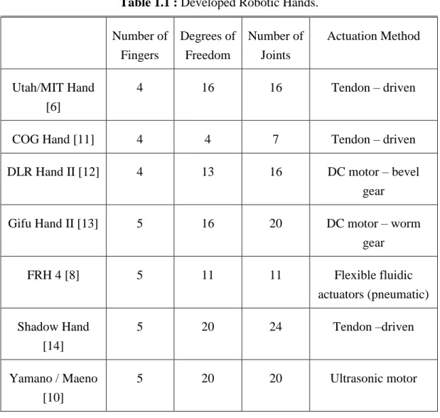
Table 1.1 : Developed Robotic Hands.
Number of Fingers Degrees of Freedom Number of Joints Actuation Method Utah/MIT Hand [6] 4 16 16 Tendon – driven
COG Hand [11] 4 4 7 Tendon – driven
DLR Hand II [12] 4 13 16 DC motor – bevel
gear
Gifu Hand II [13] 5 16 20 DC motor – worm
gear FRH 4 [8] 5 11 11 Flexible fluidic actuators (pneumatic) Shadow Hand [14] 5 20 24 Tendon –driven Yamano / Maeno [10] 5 20 20 Ultrasonic motor 1.2 Prosthesis Hands
Theodore Opuszenski designed one of the first prosthesis hands in 1951 [15]. This hand was artificial muscle actuated. His primary goal was the fact that the artificial hand should look like a real human hand and should be useful for many daily tasks. His other aims about artificial hand were; the artificial hand should be powerful, controllable, and as light as possible. This hand was designed as electrically and hydraulically operated.
8
Figure 1.9 : Designed by Thedore Opuszenski [15].
Robinson George B. designed another prosthesis hand in 1952 for amputee people [16]. The main purpose of this artificial hand was to make life easier for amputee people. In this reason, the artificial hand was controlled through the cables connected to various parts of the body. The cables took electrical signals on muscle and processed them to provide artificial hand control. This robotic hand was designed as pneumatically operated.
Figure 1.10 : Designed by Robinson George B [16].
George T. Pinson in his research talked about, robotic hands did not seem as a human hand and robotic hands had limited motion. Remote manipulators were used in a number of areas such as a nuclear field, in space, deep-sea research. In addition, a comprehensive robotic hand could not be produced because of high cost, the control difficulty and the design challenge. Pinson designed a robotic hand in 1970. The robotic hand was controlled with stepper motor and wires [17].
9
Figure 1.11 : Designed by George T. Pinson [17].
The prosthetic hand must have more than the one degree of freedom in order to be able to make multiple pattern grips in daily life. Anthropomorphic hand made by Southampton University in 2000. This robotic hand has 6 degrees of freedom. The robotic hand consists of DC motors and worm wheels. Thumb has two degrees of freedom and the other fingers have one degree of freedom [18].
Joseph T. Belter, Jacob L. Segil, Aaron M. Dollar and Richard F. Weir worked on six robotic hands with the latest technology in their work in 2013 (Table 1.2 and Table 1.3)[19].
10
Table 1.2 : Prosthesis hands for commercial purposes (general characteristics) [19].
Developer Number of Fingers
Number of Joints Degrees of Freedom Number of Actuators
Actuation Method
SensorHand [20] Otto Bock - 3 1 1 DC Motor
Vincent Hand [21] Vincent Systems
5 11 6 6 DC Motor –
Worm Gear
iLimb [22] Touch Bionics 5 11 6 5 DC Motor –
Worm Gear
iLimb Pulse [22] Touch Bionics 5 11 6 5 DC Motor –
Worm Gear
Bebionic [23] RSL Stepper 5 11 6 5 DC Motor –
Lead Screw
Bebionic v2 [23] RSL Stepper 5 11 6 5 DC Motor –
Lead Screw
11
Table 1.3 : Prosthesis hands for commercial purposes (kinematic characteristics) [19]. Metacarpal Phalanx (MCP) (⁰) Proximal Interphalanx Joints (PIP) (⁰) Distal Interphalanx Joints (DIP) (⁰) SensorHand [20] 0 – 70 ⁰ - - Vincent Hand [21] 0 – 90 ⁰ 0 – 100 ⁰ - iLimb [22] 0 – 90 ⁰ 0 – 90 ⁰ ~20 ⁰ iLimb Pulse [22] 0 – 90 ⁰ 0 – 90 ⁰ ~20 ⁰ Bebionic [23] 0 – 90 ⁰ 10 – 90 ⁰ ~20 ⁰ Bebionic v2 [23] 0 – 90 ⁰ 0 – 90 ⁰ ~20 ⁰ Michelangelo [24] 0 – 35 ⁰ - -
According to Table 1.3, DIP joints of all robotic hands are constant. There is 20 ⁰ between PIP and DIP joints in iLimb and Bebionic Hands.
1.3 Wireless Communication
Surveying through the old works, one can easily notice that, one of the most important constraints of human robot interaction has been the wired communication. Wires that are used for data transfer between human and robot are both reducing the robot mobility inside its workspace and decreasing the effective interaction range. Removing these constraints become possible in today’s technology by the help of increased usage of wireless communication protocols and the researches in this field.
The first academic studies about wireless communication dates back to 1890s. The first works were about the development and origin of telegraph [25]. Later, focused on the secrecy of wireless communication [26], which types of antennas will provide better communication [27], where can be used wireless communication [28].
Recently, many surveys and researches show that, importance of wireless communication technologies are increasing day by day in our lives [29-31]. Developments of wireless communication and electronic systems have opened the way for low-cost, low-power, low complexity wireless communication technologies [30].Also, thanks to wireless communication; we don’t need to deal with cables. These
12
technologies are used in diverse range of field. Robotic, medical, agriculture, home automation systems, military, habitat monitoring, climate etc.
Health status of the patients can be controlled continuously with wireless sensors, which are used in medical field [32]. Patient’s disease, which cannot be identified staying in a hospital, can be monitored and traced with wireless communication sensors. For example, the hearth rhythm, breathing frequency and blood pressure can be monitored while the patient is doing sport. While working, hormonal changes in the body due to stress can be monitored instantly by the doctor. Also wireless communication technologies have been proposed for emergency medical healthcare. Duncan B., Malan D., Welsh M. from Harvard University, Gaynor M. from Boston University, Moulton S., from Boston Medical Center made “VitalDust” project for Emergency Medical Care [33-34]. Also “CodeBlue” was developed by Harvard University to provide discovery, routing, naming and security for medical sensor networks [34].
With the wireless communication sensors used in the agricultural field, the temperature and humidity values of each greenhouse can be monitored instantly on a computer. Also, the condition of plants and the rate of dehydration of the soil can be controlled from range. Weather data and geo-referenced water quality can be measured via wireless communication sensors which are used in agricultural field [35].
In smart home systems, electrical devices such as air conditioning, oven, and refrigerators can be controlled by wireless communication. They can be turned on and turned off remotely. Also for security purposes, motion detector, gas detector, fire detector can be used in smart home systems to control them from remotely [36-37]. Unmanned aerial vehicles and robots can be sent to the enemy lines and gathered information about enemy with wireless technology used in military field. In the battlefield, the conditions of the soldiers can be traced. Critical terrains, approach routes, paths and straits can be watched and soldiers can be oriented immediately [30, 37].
Habitat monitoring is a new research field. With wireless communication sensors, behaviors, position, population of animals and insects can be observed. The destructive effect of human on animal and plant has increased. Intel Research Laboratory at Berkeley initiated collaboration with the College of the Atlantic in Bar Harbor and the University of California at Berkeley to monitoring temperature humidity, barometric pressure in Great Duck Island in Maine in 2002. For this purpose, they made a wireless sensor networks in Great Duck Island [38].
13 1.4 Aim of the Study
In the light of these studies, aim of the thesis can be listed as follows,
To design a lower degrees of freedom robotic hand with respect to the natural anatomy of the hand.
To control of robotic hand by the help of wireless communication protocols. To perform kinematic analysis, modeling and simulating of finger movements. To characterize actual behavior of flexible sensors.
To calibrate flexible sensors for the control task.
To achieve two degree of freedom motion by using position feedback from single flexible sensor.
To be able to grasp some solid objects by using designed robotic hands.
15
2. DEGREES OF FREEDOM AND ANATOMY OF HUMAN HAND
2.1 Forearm
Human hand and arm muscles are very sophisticated. For this reason, human hand has high dexterity motions. It can make many different movements to grasp something and to provide these motions; a number of different types of muscles are located on forearm (Figure 2.1a, Figure 2.1b). At least a pair of muscles is required for each joint movement [39].
(a) (b)
Figure 2.1 : Muscles on the forearm (a) From bottom side[45]. (b) From top side [46]
2.2. Bones of human hand and degrees of freedom
Except thumb, human fingers basically make 4 different movements. These are flexion / extension (FE), abduction / adduction (AA). The movement of the fingers towards the palm is called the flexion. Opposite of this movement is called extension.
16
Movement of the fingers towards the sides is called adduction. Opposite of this movement is called abduction (Figure 2.2). The thumb touches all the other fingers and this motion is called the opposition [2].
Figure 2.2 : Metacarpal joint motions (adduction and abduction, flexion, extension) [49].
Human hand has 14 phalanges (Figure 2.3a). There are five distal phalanges, four intermediate phalanges, five proximal phalanges. There is a joint between each phalanges (Figure 2.3b). Between distal phalange and intermediate phalange is called distal inter phalange (DIP). Between intermediate phalange and proximal phalange is called proximal inter phalange (PIP). Between proximal phalange and metacarpal is called metacarpal phalange (MCP). Thumb consist of two phalanges that’s why there isn’t intermediate phalange.
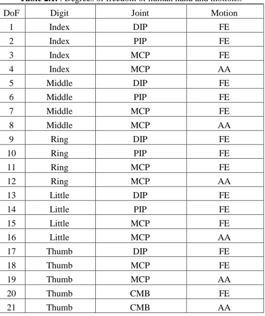
Every finger (except thumb), has 4 degrees of freedom (DoF). One DoF comes from each joint, which is between phalanges for flexion / extension (FE) movements. Totally except thumb each finger has 3 DoF for FE movements. In addition, one more DoF comes from MCP for AA movements (Table 2.1).
Thumb is the most important finger for grabbing functions. It has five DoF. Unlike other fingers, thumb can move from carpal metacarpal bones (CMC). Two DoF comes from IP and MCP for flexion and extension movements; one more DoF comes from between proximal and metacarpal phalanx for abduction and adduction movements. Also from carpal bone two DoF comes, one DoF for flexion and extension
17
movements, other one for abduction and adduction movements. Totally, human hand has 21 DoF.
(a) (b)
18
Table 2.1. : Degrees of freedom of human hand and motions.
DoF Digit Joint Motion
1 Index DIP FE 2 Index PIP FE 3 Index MCP FE 4 Index MCP AA 5 Middle DIP FE 6 Middle PIP FE 7 Middle MCP FE 8 Middle MCP AA 9 Ring DIP FE 10 Ring PIP FE 11 Ring MCP FE 12 Ring MCP AA 13 Little DIP FE 14 Little PIP FE 15 Little MCP FE 16 Little MCP AA 17 Thumb DIP FE 18 Thumb MCP FE 19 Thumb MCP AA 20 Thumb CMB FE 21 Thumb CMB AA
19
3. STANDARDS AND CONFIGURATIONS OF ELECTRONIC COMPONENTS
3.1 Standard of IEEE 802.15.4 and Zigbee Protocol
Local Area Network (LAN) is a network formed by communication between devices (computer, phone, writer, e.g.) within short distance. Wireless Local Area Networks (WLAN) is the wireless communication of these devices. With the success of the WLAN, researches in this field have increased and according to these researches, developments have increased. The directions of these developments are more dependent on low-cost, low complexity and extremely low power.
Personal Area Network (PAN) is a network used for communication among personal devices in a short distance. Wireless-PAN (WPAN) is a network, communication among personal devices is provided wirelessly.
IEEE 802 Working Group 15 is specialized to work on WPAN [40]. ZigBee is a protocol based on IEEE 802.15.4 standard, which is used in many fields including the medical field.
3.1.1 Standard of IEEE 802.15.4
Due to the need for inexpensive, low power wireless sensor network applications, in December 2000 Task Group 4, under the IEEE 802 Working Group 15, was formed to begin the development of a Low-Rate WPAN (LR - WPAN). Low-Rate means low complexity, low - cost and extremely low - power. Table 3.1 shows comparison of LR – WPAN with other wireless networks [41].
Table 3.1 : Comparison of LR – WPAN with other wireless networks [41].
WLAN BT / WPAN Low – Rate
WPAN
Range ~ 100 m ~ 10 – 100 m 10 m
Data Throughput 11 Mb/s 1 Mb/s < 0.25 Mb/s
20
Table 3.2 :IEEE 802.15.4 High Level Characteristics [41].
Frequency Band Two PHYs Low-Band (BPSK) 868 MHz 1 channel - 20 kb/s 915 MHz 10 channels - 40 kb/s High-Band (O-QPSK) 2.4 GHz 16 channels - 250 kb/s Channel Access CSMA-CA Range 10 - 20 m
Addressing Short 8 bit or 64-bit IEEE
According to Table 3.2 IEEE 802.15.4 standard consist of two bands, Low-Band and High-Band. Low-Band is specified to operate in 868 MHz in Europe with 1 channel, 20 kb/s data rate and in 915 MHz in America with 10 channels, 40 kb/s data rate. High-Band is specified to operate in 2.4 GHz nearly for whole world with 16 channels, 250 kb/s data rate [41].
3.1.2 Zigbee
ZigBee is a protocol, which uses IEEE 802.15.4 sub-structure. On Table 3.3, well-known wireless sensor networks were compared.
21
Table 3.3 : Wireless Communication Networks [42,52].
ZigBee GPRS/GSM Wi-Fi Bluetooth
Focus Area Monitoring and Control
Voice and Data Transmission Internet Email Instead of Cable System Resource 4 – 32 KB 16 MB+ 1 MB+ 250 KB+ Battery Life (Day) 100 – 1000+ 1 - 7 0,5 – 5 1 – 7
LAN Size Unlimited 16 Mb+ 32 7
Bandwidth (KB/s) 20 - 250 64 – 128+ 11000 720 Range(Meter) 1 – 100+ 1000+ 1 – 100 1 – 10+ Successful Areas Power Consumption and Durability Access and Quality Speed and Flexibility Cost and Convenience
According to Table 3.3, the most important feature of ZigBee is the low power consumption. In addition, even the minimum number of days for battery life is considerably higher than the other networks.
3.2 Zigbee Device Types And Network Topologies
3.2.1 Zigbee device types
ZigBee networks have three different device types; coordinator, router and end device. Coordinator, as the name implies, coordinates the network. Define, set and protect the network, and specify the communication of the addresses. In each network, there can be only one coordinator. To achieve communication, there must be one more device. The routers are responsible for routing traffic between different nodes. Router carries information between other devices on the network. It is like a messenger. There can be more than one in each network. Other name of router is Full Functional Device (FFD).
End devices only receive and transmit data. Other name of end device is Reduced Functional Device (RFD). As the name implies they cannot communicate with other devices. They always need router or coordinator. End devices can go to sleep mode when they do not communicate. This mode saves energy. End device is the reason of long battery life of XBees.
22
The functions and the differences of the three devices are given at Table 3.4. Table 3.4 : Comparison of ZigBee Devices [50].
ZigBee Network Layer Function Coordinator Router End Device
Establish a ZigBee network
Permit other devices to join or leave the network
Assign 16-bit network addresses
Discover and record paths for efficient message delivery
Discover and record list of one-hop neighbors
Route network packets
Receive or send network packets
Join or leave the network
Enter sleep mode
3.2.2 Zigbee network topologies
There are four types of ZigBee network topology (Figure 3.1).
Figure 3.1 : ZigBee network topology [43].
Pair is the simplest network topology. There are two devices in this network. One of them is coordinator and the other one can be router or end device. Only these two device communicate.
23
In star topology, all devices are connected to the coordinator. All messages must pass through the coordinator. The coordinator distributes the message. Other devices can’t communicate with each other. Generally, end devices are reason for preference in this topology because of energy saving. Usage areas of this topology is home automation systems, personal computer peripherals and toys.
In mesh topology, messages are transmitted through routers. The coordinator is responsible for the management of the network. In addition, it decide to distribute messages. Router can communicate with the router, end device and the coordinator. Mesh network can make ad – hoc, routing and self – healing. Other name of mesh network is peer-to-peer. Usage areas of mesh topology is Industrial control and imaging.
Cluster tree is similar to mesh topology. In this topology, routers cannot communicate directly.
3.3 Xbees And Configuration Of Xbees By Using X-CTU
3.3.1 XBee
XBee is a wireless antenna, which uses 802.15.4 LR-WPAN protocol for communication in 898 MHz, 915 MHz and 2.4 GHz operating frequency. There are two basic XBee radio hardware; XBee S1 and XBee S2. In addition, there are two different data transfer mode. First one is the transparent (AT) mode and second one is the Application Program Interface (API) mode.
XBee S1 is based on point-to-point communication. That’s why, it is good at AT mode. AT mode is good at when sending and receiving a single data. Experiment was made for using two different data in AT mode. Sometimes second data was read as first data. In this project, nine variables are sent. In this case, data are more likely to interfere. XBee S2 is based on mesh networking. Therefore, it is better on API mode. API mode provides to data to be sent in packets. Therefore, data interfere that occurs in AT mode does not occur in API mode. Also power consuming of XBee S2 is less than XBee S1. Comparing of XBee S1 and S2 are showed in table 3.5.
24
Table 3.5 : XBee S1 versus XBee S2 [43].
Series 1 Series 2
Typical (indoor/urban) range 30 meters 40 meters Best (line of sight) range 100 meters 120 meters
Transmit/Receive current 45/50 mA 40/40 mA
Firmware (typical) 802.15.4 point-to-point
ZB ZigBee mesh
Digital input/output pins 8 11
Analog input pins 7 4
Low power, low bandwidth, low cost, addressable, standardized, small,
popular
Yes Yes
Interoperable mesh routing, ad hoc network creation, self-healing
networks
No Yes
Point-to-point configuration Simple More involved
Underlying chipset Freescale Ember
XBee S1 uses the basis of IEEE 802.15.4. XBee S2 built on top of 802.15.4. This means, 3 features are added on XBee S2. 1- Routing, 2- ad hoc network creation, 3- self-healing networks.
Routing is the process of selecting the way in which different networks use each other to communicate with each other. Ad – Hoc Network Creation is an automated process that creates an entire radio network without human intervention. In a network, when one or more radio is missing, Self – Healing Network provides to reconfigure the network to repair any broken routes [43].
There are two basic rules to provide a communication between XBees. First, XBee’s must be in the same version in order to communicate with each other. That is, XBee S1 communicate with S1, and XBee S2 communicate with S2. Second, XBee’s must be configured. To configure XBee, computer connection is needed. This
25
communication is provided by XBee adapters (Figure 3.2). Another method to computer connection, XBee is connected to Arduino and Arduino is short-circuit. But in this method Arduino may be harmed, so it is not preferred.
Figure 3.2 : XBee usb adapter.
XBee radio has 20 connection pins (Table 3.6). There are 2 mm distance between two pins. For this reason, XBee cannot be placed on breadboard directly and XBee breakout boards are needed (Figure 3.3). In addition, XBee pin directions are shown in Table 3.6.
26
Table 3.6 : Pins of XBee S2 [43].
Pin # Name(s) Description
1 VCC 3.3 V power supply
2 DOUT Data Out (TX)
3 DIN Data In (RX)
4 DIO12 Digital I/O 12
5 RESET Module reset (asserted low by bringing pin to ground)
6 PWM0/RSSI/DIO10 Pulse-width modulation analog output 0, Received Signal Strength Indicator, Digital I/O
10
7 DIO11 Digital I/O 11
8 Reserved Do not connect
9 DTR/SLEEP_RQ/
DIO8
Data Terminal Ready (hardware handshaking signal), Pin Sleep Control (asserted low), Digital
I/O 8
10 GND Ground
11 DIO4 Digital I/O 4
12 CTS/DIO7 Clear to Send (hardware handshaking), Digital I/O 7
13 ON/SLEEP Sleep indicator (off when module is sleeping)
14 VREF Not used in Series 2
15 ASSOC/DIO5 Association indicator: blinks if module is associated with a network, steady if not; Digital
I/O 5
16 RTS/DIO6 Request to Send, Digital I/O 6
17 AD3/DIO3 Analog Input 3, Digital I/O 3
18 AD2/DIO2 Analog Input 2, Digital I/O 2
19 AD1/DIO1 Analog Input 1, Digital I/O 1
20 AD0/DIO0/COMMIS Analog Input 0, Digital I/O 0, Commissioning Button
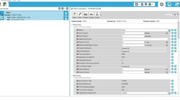
27 3.3.2 Configuration of XBees by using X-CTU
X-CTU is a Windows-based application (Figure 3.4). X-CTU software was used to perform change configurations of XBee.
Figure 3.4 : X-CTU.
Each XBee has a unique and permanent 64-bit serial number. Serial number of our XBee’s 0013A20041257609 and 0013A2004125760A. Serial numbers separate two parts. First part is Serial Number High (SH); 0013A200 is the SH. Other part is Serial Number Low (SL); the part that comes after 13A200 is forming SL. SL of our XBee’s are 41257609 and 4125760A.
3.3.2.1 Channel
The channel controls the frequency band in which the XBee communicates. Most of XBees work on 2.4 GHz on 802.15.4 band. Channel operates frequency of this band. 3.3.2.2 Pan address
Pan Address is a 16-bit address specific to the network, which is set after the network is created. There are 65536 Pan ID. XBees can only communicate when they have same Pan ID in network.
3.3.2.3 My address
Each Xbee must be set with a 16 bit address on the network. Other name is Source Network.
28
Figure 3.5 : Venn diagram of XBee network [43].
3.3.2.4 Destination address
Destination Address specifies the source address of another XBee to send data. In order to send data from one XBee to another XBee, destination address of first XBee must be the same as the source address of second XBee. There are two configurations of Destination Address. These are Destination High Address (DH) and Destination Low Address (DL).
SH and SL numbers can be set as DH and DL for two XBees to send and receive data between each other. In this thesis, since only two XBees is used, the source addresses of each other are used to communicate between each other (Table 3.7).
Table 3.7 :XBee configurations.
XBee Parameters (Arduino Mega)
Transmitter Receiver CH E CH E PAN ID 8500 PAN ID 8500 DH 13A200 DH 13A200 DL 4125760A DL 41257609 BD (Baud Rate) 9600 BD 9600
AP (API Enable) API enabled with
escaping AP (API Enable)
API enabled with escaping
29
4. DESIGN AND MANUFACTURING OF ROBOTIC HAND
4.1 Design Criteria and Component Descriptions
Design and manufacturing of the robotic hand consists of three parts. The first part is the design and production of mechanical parts. The second part is the design of Arduino circuit and programming Arduino. The third part is calibration of flexible sensor.
Some criteria and constraints were considered during the design of hand. These criteria and constraints are grabbing ability, fingers should move independently, robotic hand should be anthropomorphic, degrees of freedom of the hand, cost, developable. Design criteria and constraints of the robotic hand were ordered as follows:
The robotic hand should be able to simulate most of the linear movements of a human hand, which are necessary for useful work.
The robotic hand should be capable of simulating the linear optimal hand movements of an adult human hand and robotic hand is maintained substantially proportional size and shape of an adult human hand.
Thumb of robotic hand should touch the distal phalanges of other fingers. All fingers of robotic hand should move independently.
The robotic hand should be able to grab materials which have different shapes. Cost of robotic hand should be inexpensive.
The robotic hand should be developable with open-source code. The robotic hand should act in real time with human hand.
4.2 Designing and Manufacturing of the Robotic Hand
Main aim of the design was the robotic hand has to be able to simulate most of the linear movements of a human hand, especially necessary for useful works in daily living. In addition, size of robotic hand should be close to the average size of an adult human hand. The robotic hand should be able to grab some materials in different shapes.
30
Designed robotic hand has 9 degrees of freedom. When designing the robotic hand, it was considered to be anthropomorphic. All the mechanical parts were designed in Autodesk Inventor.
Firstly, robotic fingers were designed. Secondly, hand was designed. All structures were proportionally sized as in an adult human hand. The 3D models of robotic hand were also inserted in the assembly drawing in order to check the compatibility of all the pieces.
After assessing the compatibility of the mechanical parts of the robotic hand, simulation were made in Motion Study in SolidWorks. The mechanical parts of the hand were produced by using 3D printer ATOM.
4.2.1 Finger and hand sizes
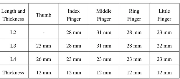
Index finger, middle finger, ring finger and little finger consist of three phalanges. Thumb consists of two phalanges. Length of index finger (Figure 4.1) and ring finger are same. Thickness of all fingers is the same. Size and lengths of fingers are shown in Table 4.1. In addition, hand sizes are shown on Figure 4.2. All values are in millimeter.
31
Figure 4.2 : Palm sizes (mm).
Table 4.1 : Finger sizes in length and thickness.
Length and Thickness Thumb Index Finger Middle Finger Ring Finger Little Finger L2 - 28 mm 31 mm 28 mm 23 mm L3 23 mm 28 mm 31 mm 28 mm 22 mm L4 26 mm 23 mm 23 mm 23 mm 23 mm Thickness 12 mm 12 mm 12 mm 12 mm 12 mm
4.2.2 Tendon – wire systems
Three different tendon-wire systems are used, n, 2n and n + 1 tendon. There are two different structures in n tendon systems. The first one is the shown in Figure 4.3a.
32
Actuator is used for the flexion movement. When the actuator releases the wire, thanks to pretension spring fingers make extension movement. Second system is the shown in Figure 4.3b. A single actuator and two opposed tendons are used for flexion and extension movement. The advantage of n-tendon system is reduced set of required actuators, according to 2n system. When pretension spring is used in n tendon system, if applied force is excessive or if the system is used heavily, it will be worn faster than the two opposed tendon systems. The purpose in 2n tendon systems is to increase the flexibility, accuracy and precision of the movements of the robotic hand (Figure 4.3c). On the other hand, the complexity of the system increases due to the used number of actuators. In n + 1 tendon systems, n + 1 tendon and actuator are used, to control n independent joints (Figure 4.3d). This system reduce complexity according to 2n-tendon system. While flexion movements of fingers controlling with two actuators, extension movements is controlled with one actuator [2]. For all tendon systems, movement gaps is a problem because of the tendons.
(a) (b)
(c) (d)
Figure 4.3 : Tendon – wire systems (a) n-tendon system with pretension spring. (b) n-tendon system with two opposed tendons. (c) 2n-tendon system. (d) n+1
tendon system [2].
Robotic hand fingers are controlled with the n tendon-wire system with two opposed tendons. Distal and proximal phalanges for index, middle, ring and little fingers have four holes (Figure 4.4a). First and second holes are inside of the distal and proximal phalanges. Third and fourth holes are the outside of these phalanges. These holes are used to connect wires to control robotic fingers. Thumb has only one wire connection
33
to distal phalanges. The holes on the inside of fingers are used for flexion movements; the holes on the outside of fingers are used for extension movements.
Phalanges of each robotic finger have two gaps from end to end. These gaps are for passing through wires. One gap at the bottom side, other one is at the top side (Figure 4.4a).
For each finger, there are two independent motion except thumb. Thumb has one degrees of freedom. Therefore, robotic hand has nine degrees of freedom. In addition, there are five under actuated joints. These are intermediate phalanges and for thumb proximal phalanges. Totally, the robotic hand has 14 DoF.
After all the mechanical parts were designed, they were assembled in Inventor for checking the compatibility of parts (Figure 4.5).
a b
Figure 4.4 : a-) First partof index finger, view from bottom side. b-) First part of index finger, view from top side.
34
Figure 4.5 : Assembly of robotic hand.
Palm of robotic hand holes for tendon-wire system were shown in Figure 4.6.
35 4.2.3 Kinematic analysis of fingers
Drawing trajectory of fingertips and movement of fingers were observed in Motion Study in SolidWorks. The orbits shown in Figure 4.8 were created by adding actuators to the joints and using the SolidWorks. The following formulas are time - dependent kinematic analysis of finger. The rotation coefficients of the articulations were taken as k1 = 10, k2 = 9 and k3 = 9.
Figure 4.7 : Kinematic models of finger in X, Y plane. Table 4.2 : Denavit – Hartenberg parameters.
Joint i a𝑖−1 𝛼𝑖−1 di 𝜃𝑖
1 0 0 0 𝜃1
2 L2 0 0 𝜃2
3 L3 0 0 𝜃3
4 L4 0 0 0
Tip point coordinates of three DoF finger are written as follows, 2Cos( ( ))1 3Cos( ( ))2 4Cos( ( ))3
x
P L
t L
t L
t (4.1)2Sin( ( ))1 3Sin( 2( )) 4Sin( ( ))3
y
P L t L t L t (4.2)
where θ1(t) = a(t). k1, θ2(t) = a(t). k2, θ3(t) = a(t). k3 and a(t) = ω. r. t . In these formulas, Px (t) and Py (t) show the position of the last point of the fingers
changes with the time. θ1(t), θ2(t) and θ3(t)show the rotation angels of distal, middle and proximal parts of robotic fingers. All rotation angle depend on movement of wire which provides the movement of robotic fingers, defined by a(t), are dependent on
36
time. r is the radius of pulley which the rope is wrapped. ω is angular velocity of actuator.
Figure 4.8: Drawing trajectory of fingertips.
In addition, a spherical body was grabbed by robotic hand in Motion Study (Figure 4.9). The simulation was realized while each finger was moving at the same time and used solid contact between the fingers and spherical body.
37
(a) (b)
(c) (d)
Figure 4.9 :Simulation of grabbing a spherical body. (a) t=1s. (b) t=4s. (c) t=6s. (d) t=7s.
4.2.4 Working Area of fingers
Working area of robotic fingers was created on MATLAB. If robotic fingers has three degrees of freedom, working area will be at figure 4.10 and figure 4.11. Codes of figure 4.10 and 4.11 are given in Appendix A. Designed robotic fingers are controlled with two servos, except thumb. Therefore, they have two independent motions. Thumb is controlled with one servo. First servo motor controls the distal phalange and second servo motor controls the proximal phalange. That is why, firstly, distal phalanges start to rotate. When it reaches to 90⁰ degrees, intermediate phalanges start to rotate. In this situation, workspace of robotic fingers will be at figure 4.12 and figure 4.13. Codes, for first and second situation are given in Appendix B, C. For first working area (Figure 4.13), distal and proximal phalange were rotated from 0⁰ to 90⁰, and intermediate phalange was considered as a fixed part. In Figure 4.15, the distal phalange was
38
considered as a vertical part of intermediate phalange. Intermediate and proximal phalange were rotated from 0⁰ to 90⁰ degrees.
Firstly, the working area was swept with 0.1 radians (Figure 4.10). However, the swept area was not clear enough. Therefore, the sensitivity was increased and the working area was swept with 0.01 radians (Figure 4.11).
In figure 4.14, Figure 4.13 and Figure 4.12 were combined in MATLAB. Thus, obtained working area of index finger of robotic hand. Robotic finger was accepted as index finger and measurements were given at Table 4.1.
Also to see difference between two working areas, Figure 4.15 was drawn in MATLAB. Combed area is difference between the three DoF and two DoF index finger working area. In addition, some movements of fingers were shown in Table 4.3.
39
Figure 4.11 : Working area of robotic index finger (0.01radians).
40
Figure 4.13 : Second condition.
41
Figure 4.15 : Dotted area is the difference between the 3 DoF and 2 DoF index finger working area.
42
43 4.2.5 Inverse kinematic analysis of fingers
Figure 4.16 : Parameter of Index Finger. 𝜃13 begins to change after 𝜃14 reaches to 90⁰. So;
1 14 14 1 14 13 0 , , 90 t t t t (4.3)
𝑡1will be determined by experiments in experimental test part. 𝜃14 changes according to motor speed. So equations (4.1) and (4.2) are used again
1Cos( 12( )) 2Cos( 13( )) 3Cos( 14( ))
x
P L
t L
t L
t (4.4)1Sin( 12( )) 2Sin( 13( )) 3Sin( 14( ))
y
P L t L t L t (4.5)
Square of equations (3.4) and (3.5) are added.
2 2
1 12 1 12
2 2
2 13 3 13 2 13 3 13
( Cos( ( ))) ( Sin( ( )))
( Cos( ( )) Sin( ( ))) ( Sin( ( )) Cos( ( )))
x y P L t P L t L t L t L t L t (4.6) 2 2 2 2 2 2 3 x 1 y 2 x 1Cos 12 2 y 1Sin 12 L L P L P P L P L (4.7) 2 2 12 2 2 1 Cos 1 t t (4.8) 2 12 2 2 2 Sin 1 t t (4.9)
44 12 2 tan 2 t (4.10) 2 2 2 2 2 2 2 2 1 2 1 2 2 3 1 2 2 1 2 0 2 2 1 1 x y x y t t P L P L L L P L P t t (4.11) 2 2 2 2 2 2 2 1 2 1 2 2 2 3 1 0 2P Lx (1t ) 4 P L ty (1 t )( L L Px L Py) (4.12) 2 2 2 2 2 2 2 2 3 1 1 2 2 2 2 2 1 2 2 3 1 1 0 ( 2 ) 4 ( 2 ) x y x y x y x t L L P L P P L P L t L L P L P P L (4.13) 2 2 2 2 2 2 3 1 1 ( x y 2 x ) A L L P L P P L (4.14) 2 2 2 2 2 2 3 1 1 ( x y 2 x ) C L L P L P P L (4.15) 2 1 1 2 4 ( 4 ) 4 2 y y P L P L AC t A (4.16) 12 2 arctan( )t2 (4.17) 1 12 2 3 1 12 13 2 2 13 2 3 13 1 12 3 2 1 12 2 2 3 13 2 13 ( Cos( ) ( Sin( ))) arctan 2( ), Cos( ) Cos( ) ( Cos( ) ( Sin( ))) Sin( ) Sin( ) x y x y P L L L P L L L P L L L P L L L (4.18)
4.2.6 Controlling of robotic hand
Controlling of robotic hand was provided via servo motors. Nine servo motors were used. In addition to robotic hand, another part was designed to position servo motors like a wrist (Figure 4.17).
45
Figure 4.17 :Wrist to position servo motors.
In addition, MG 996R servo motors and wrist were assembled in Inventor for checking the compatibility of parts (Figure 4.18).
47
5. CHARACTERIZATION AND CALIBRATION OF SENSORS
Flexible sensor acts like a potentiometer. Its resistance changes depending on bend radius of it. Resistance value of flexible sensor is 25K ohms while it is on flat position. Resistance range of flexible sensor changes between 45K and 125K ohms depending on bend radius of it [51].
In this study, five flexible sensors were used to measure angles of real hand fingers. Flexible sensor gives an output voltage in range of 5V – 0V according to bend radius (Figure 5.1). Resistance tolerance of flexible sensors is ±30% [51]. This tolerance value is too much. Firstly, to avoid the tolerance value characterizing studies were done. Some researches were made and formulas were tried to find out. Finally, calibrations were made.
Figure 5.1 : The working principle of the flexible sensors [51].
In order to read sensor output, the output pin of the flexible sensors was attached on one of the analog input pins of Arduino Mega ADK. Arduino analog pins give a 10-bit analog output value between 0 and 1023 which changes according to 0V to 5V. Since sensor does not give directly the bend angle output, the output value of sensor should be converted to meaningful angle output.
To take a meaningful formula, bend position of flexible sensor were tried in different types of equations and graphs. The analog output values of flexible sensor were recorded for different bend positions. 10k ohm resistor was connected for each experiment. The software Mathematica was used to find a curve fit function and plot function for the recorded data.
48
There are white and black nodes on flexible sensor (Figure 5.2). Apart from pins which are on flexible sensor, measurements can be taken from these nodes. White nodes on flexible sensor can be considered as a resistance and these are connected as serially. First white square, which is closed to the pins have the highest resistance. Because it is far away to the ground pin.
Also flexible sensor can be thought as a rubber. If rubber is stretch it will be thin. Resistance on thin wire is more according to thick wire. That’s why, if flexible sensor is bended resistance will increase (Figure 5.1).
Firstly, flexible sensor positioned on flat position. Values on Table 5.1 were created, taken from on each white square of flexible sensor while it was on flat positon. There is approximately 4,2 – 4,3 mm distance between centers of each white square. Therefore, on X – Y plane beginning point was chosen zero and first white square of flexible sensor positioned to 0 point. Then measurements were taken at 4,2 – 4,3 mm intervals. Table 5.2 shows the formula and graphic for flat position measurements.
Table 5.1 :Analog output values of flexible sensor. Flat Position
Measurements on Each White Square
Centimeter Measurement Centimeter Measurement
0 636 4.75 480 0.4 627 5.2 455 0.9 615 5.6 430 1.3 605 6 390 1.75 590 6.45 358 2.15 578 6.85 315 2.6 560 7.3 257 3 545 7.75 257 3.45 527 8.3 166 3.9 508 8.6 120 4.3 495 9 67
49
Figure 5.2 : Flexible sensor.
Table 5.2 : Formula and graphic according to flat position.
Gr aphic V(scaled) cm C ode s data = {{0, 636}, {0.4, 627}, {0.9, 615}, {1.3, 605}, {1.75, 590}, {2.15, 578}, {2.6, 560}, {3, 545}, {3.45, 527}, {3.9, 508}, {4.3, 495}, {4.75, 480}, {5.2, 455}, {5.6, 430}, {6, 390}, {6.45, 358}, {6.85, 315}, {7.3, 257}, {7.75, 212}, {8.3, 166}, {8.6, 120}, {9, 67}}; fit = FindFormula[data, x] 619.4667271781079 − 6.66061954665892𝑥2
Show[ListPlot[data], Plot[fit, {x, -20, 60}, PlotRange -> All]]
2 4 6 8 100 200 300 400 500 600
![Figure 1.3 : Designed by James F. Mullen [5].](https://thumb-eu.123doks.com/thumbv2/9libnet/3708589.24907/27.892.199.763.684.1015/figure-designed-by-james-f-mullen.webp)
![Figure 1.4 : Designed by UTAH / MIT [6].](https://thumb-eu.123doks.com/thumbv2/9libnet/3708589.24907/28.892.233.589.400.659/figure-designed-utah-mit.webp)
![Figure 1.5 : Designed by Carl F. Ruoff and Salisbury [7].](https://thumb-eu.123doks.com/thumbv2/9libnet/3708589.24907/29.892.339.618.103.507/figure-designed-carl-f-ruoff-salisbury.webp)
![Table 1.2 : Prosthesis hands for commercial purposes (general characteristics) [19].](https://thumb-eu.123doks.com/thumbv2/9libnet/3708589.24907/34.1262.111.1163.202.671/table-prosthesis-hands-commercial-purposes-general-characteristics.webp)
![Table 3.2 :IEEE 802.15.4 High Level Characteristics [41].](https://thumb-eu.123doks.com/thumbv2/9libnet/3708589.24907/44.892.105.726.151.479/table-ieee-high-level-characteristics.webp)
![Table 3.5 : XBee S1 versus XBee S2 [43].](https://thumb-eu.123doks.com/thumbv2/9libnet/3708589.24907/48.892.106.726.131.785/table-xbee-s-versus-xbee-s.webp)