Title Page
Computed Tomography-guided Optimization of Needle
Insertion
For
Combined
Intracavitary/Interstitial
Brachytherapy With Utrecht Applicator in Locally Advanced
Cervical Cancer
Short running title: CT-Guided needle insertion during IS-ICBT
Makbule Tambasa, MD, Busra Tavlib, MSc, Nazli Bilicib, MSc , Aysen Dizmanb, MD, Huseyin Sertelb, MSc, Merdan Faydab,c, MD
a
University of Groningen, University Medical Center Groningen, Department of Radiation Oncology, Groningen, the Netherlands
b
Liv Hospital Ulus, Department of Radiation Oncology, Istanbul, Turkey
c
Istinye University, Faculty of Medicine, Department of Radiation Oncology, Istanbul, Turkey
Corresponding Author and Statistical Analysis Author: Makbule Tambas, MD
University of Groningen, University Medical Center Groningen, Department of Radiation Oncology, Hanzeplein 1, 9713 GZ Groningen, the Netherlands
e-mail:[email protected] ,telephone: +31 050 361 6161
Conflict of Interest: None Funding: None
Data sharing statement: Research data are not available at this time.
Acknowledgement: This study is accepted as oral presentation for Turkish Radiation Oncology Annual Meeting in 2021. We would like to thank Editage (www.editage.com) for English language editing.
Computed Tomography-guided Optimization of Needle Insertion For Combined
Intracavitary/Interstitial Brachytherapy With Utrecht Applicator in Locally Advanced
Cervical Cancer
ABSTRACT
Purpose: There are no international guidelines for optimal needle insertion during interstitial
intracavitary brachytherapy (IS-ICBT) for cervical cancer. We aimed to investigate the clinical feasibility and added value of computed tomography (CT) guidance to optimize needle insertion in IS-ICBT using the Utrecht applicator and to evaluate needle shifts.
Methods and Materials: We enrolled 24 patients who were treated with IS-BT. Two CT
scans each were performed for every patient: 1) after applicator insertion without needles (CTpreneedle); 2) after needle insertion (CTpostneedle). In addition to magnetic resonance imaging
(MRI) after external-beam radiotherapy, CTpreneedle was used to determine optimal needle
locations and insertion lengths based on applicator and organs at risk positioning on the day of treatment; CTpostneedle was used for IS-ICBT planning. The needle-channel axis was used as
a reference to determine needle-shift evolution.
Results: A total of 266 interstitial needles were inserted in 76 of 93 BT fractions with high
intra- and interpatient variations in the number of inserted needles. Based on CTpreneedle
findings, needle insertion was avoided in nine, four, two, and two patients at the first, second, third, and fourth fractions, respectively. The unloaded needle frequency was 4%. Average needle contribution to total dwell time was 37.2±19.2%. Shifting was observed in 68% of the needles (mean shift 2.0±2.3 mm), mostly in the posterior direction, and in needles with a larger insertion length. Needle reinsertion was not needed in any patient. No complication due to needle insertion was observed, except for minor vaginal bleeding in one patient after
Conclusion: The adaptive CT-guided IS-ICBT application was feasible and resulted in fewer
unloaded needle insertions or complications and more efficient use with higher needle contribution to the treatment. Needle shift was frequent but did not require needle reinsertion with the proposed method.
Introduction
The addition of interstitial-brachytherapy (IS-BT) to intracavitary-BT (IC-BT) significantly increased the 3-year local control rate by 10%, without a significant increase in the toxicity, in patients with locally advanced cervical cancer, especially in those with a larger high-risk clinical target volume (CTVHR; ≥30 cm3).1 IS-BT not only enables an adequate-dose coverage
of the parametrial extension of the tumor, but also surmounts topography-related problems.2 Magnetic resonance imaging (MRI) performed in the last week of external-beam radiotherapy (EBRT; MRIpostEBRT) is frequently used to evaluate the indication for IS-BT.
MRIpostEBRT provides information on the tumor response to EBRT and helps to identify the
parts of the CTVHR located outside the IC-BT coverage. However, other factors, including
organ movement and suboptimal applicator insertions, that influence IS-BT indication cannot be assessed via the MRIpostEBRT. Substantial organ movement that caused a ≥10% change in at
least one organs at risk (OAR) dose has been demonstrated in up to 61% of patients.3 Furthermore, suboptimal tandem insertion has been reported in 3.0–13.7% of BT applications.4-7 Unless a perforation occurs, the BT session is not terminated, and treatment is applied in most cases. However, this suboptimal insertion may lead to a significant dose increase in the surrounding OARs based on the direction of insertion.8 Unforeseen indications for IS-BT may emerge due to either organ movement or suboptimal tandem insertions that
can only be assessed just before needle insertion and after the tandem has been inserted into the patient.
Several types of IS-BT applicators, including the tandem-ovoid Utrecht applicator (Elekta, Veenendaal, The Netherlands), have been reported to provide considerable superiority over the traditional IC applicators in terms of target coverage and OAR doses.1, 9,
10
The clinical application of Utrecht IS-BT applicator needles was demonstrated by Nomden et al.9 Smolic et al. further analyzed the frequencies of the needle channel location that was used, the inserted but unloaded needles, and needle channels with the lowest contribution.11 However, there are no international guidelines to determine which needles should be used, how to increase the optimal use of needles, and when and how frequently to perform the imaging before the first and subsequent BT fractions for preplanning needle insertion. Furthermore, no clinical data have been reported with regard to a shift in the needles after insertion.
Therefore, we aimed to investigate the clinical feasibility and added value of computed tomography (CT)-based guidance in the optimization of needle use during IS-BT using an Utrecht applicator. In addition, we evaluated the differences between the planned and inserted needles in terms of shift magnitude and direction.
Methods and Materials
Patients and treatment
Between May 2018 and January 2020, 74 patients with inoperable cervical cancer were evaluated for BT at XXX following EBRT, scheduled at 45–50.4 Gy/25–28 fr, and concomitant weekly cisplatinum (40 mg/m2). Among these, 32% (n=24) of the patients were
recognized as an IC/IS center based on the definition used in the retroEMBRACE study.1 The BT was scheduled as 6.5-7.5 Gy in 3 to 4 fractions based on the EBRT dose.
All the treatment procedures reported in this study were a part of the routine clinical practice in our institution and were conducted after obtaining consent as relevant. The ethics committee deemed that additional informed consent for this study was not required, based on the XXX Medical Research Involving Human Subjects Act. However, all patients were informed that their data could be used for research purposes and that they could refuse consent for such use.
MRIpostEBRT imaging was performed in the last week of EBRT to evaluate the patient’s
response and suitability for BT, which was planned within the first week after EBRT completion in patients with optimal blood levels.
The BT was performed under sedoanalgesia: 2–3 mg midazolam IV and 40–60 mg meperidine IV were administered to the patient before the insertion of the applicator, followed by a second dose of 1 mg and 10–20 mg, respectively, before needle insertion. All patients prophylactically received 1 g ceftriaxone IV before applicator insertion. The patient records were complete, and there were no missing data for the parameters evaluated in this study.
CT-guided needle insertion
The decision tree and clinical workflow for the IS-ICBT indication are shown in Figure 1. Instead of determining the IS-BT needle use and locations solely based on the tumor extension in the MRIpostEBRT, we performed two CT imaging (pre- and postneedle CT) in
addition to the MRIpostEBRT:
1) CTpreneedle: CT imaging was performed without needles after the IC applicator was
applied in the patient (Figure 2).
2) CTpostneedle: A second CT imaging was performed after the needles were inserted into
the patient (Figure 2).
The applicator was inserted in the operation room while the patient was under sedoanalgesia. Then, the patient was transferred to the CT room and CTpreneedle was performed. In addition to
the information provided by the MRIpostEBRT, information obtained from the CTpreneedle was
used by a radiation oncologist to decide the needle channels and insertion lengths, evaluating the position of the applicator, OAR proximity to the target on that day, and the parts of the target extending beyond the applicator’s coverage capacity. It took approximately 5 minutes to evaluate CTpreneedle for needle insertion indication, length, and channels. If an IS-ICBT plan
with optimal target coverage and acceptable OAR doses could be created without using needles, then needles were not inserted and patient was transferred to the treatment room and waited until IC-BT planning was created using the CTpreneedle.
If needle insertion was indicated based on CTpreneedle findings, needles of the specified length
were inserted through the determined channels using a special apparatus, while the patient was lying on the CT table. Following needle insertion, CTpostneedle was performed (Figure 2).
All these processes (CTpreneedle scanning and its evaluation, insertion of needle(s) and
CTpostneedle scanning) took up to 20 minutes, depending on the number of needles inserted into
the patient.
Decision making for IS-BT
Four main parameters played a role in decision making for IS-BT:
Journal Pre-proof
2) The suboptimal dose distribution of the previous ICBT fraction without needles, i.e., covering CTVHR with proper dose was not possible without exceeding OAR
doses limits in the previous ICBT fraction.
3) The positioning of the applicator on the day of treatment: Applicator-anatomy mismatching: the suboptimal positioning of the applicator inside the uterus which interfered with proper CTVHR coverage or led to unacceptable OARs doses.
4) The positioning of the OARs on the day of treatment: An OAR located in the or close by the high dose region, generally valid for sigmoid colon.
CT scanning was performed with a 1.25-cm slice thickness using the GEHC Discovery CT750 HD (Waukesha Wisconsin, USA). Three-dimensional BT planning was performed using the Oncentra Brachytherapy Planning System (BPS) v4.5.3 (Elekta, Veenendaal, The Netherlands) after contouring of the residual gross tumor volume (GTVres),
CTVHR, and OARs, including the bladder, rectum, sigmoid, and small bowel, on the
CTpostneedle.12-15 The plan was initiated by activating all source positions and was continued by
manual optimization of the dwell times in the channels of the intrauterine tandem, ovoids, and needles.
In patients who had completed the treatment, the procedure was terminated by removing the needle(s) and, subsequently the applicator, followed by vaginal washing with a povidone iodine solution. The patient was invited to the next BT fraction after an interval of at least 72 hours.
Dosimetry goals
The summed biologically equivalent doses in 2-Gy fractions (EQD2) of EBRT and BT were calculated with α/β of 10 (EQD210) and 3 (EQD23) for CTVHR and OARs, respectively. The
aims and limits of planning in the EMBRACE II protocol were used during plan
Journal Pre-proof
optimization.16 The plan was visually inspected by a radiation oncologist to ensure that the reference isodose (100%) optimally covered the CTVHR, fully covered the GTVres, and did
not extend to the OARs; the 200% isodose was within the CTVHR and ovoids.
The doses in the target and OARs as well as the number of needles used were compared between patients with large (≥30 cm3) and small (<30 cm3) CTVHR, based on the
CTVHR volume in the first BT fraction.
Needle dwell intensities
We coded the location of the needles in three letters as follows: the first letter represented whether the needle was on the left (L) or right ovoid (R); the second letter indicated lateral (L) or medial (M) positioning; and the last letter denoted anterior (A), medius (M), or posterior (P) positioning of the needles. Thus, LMA indicated a needle on the left ovoid with medial and anterior positioning (Figure 1S).
We examined the clinical use of needles, depending on how often each of the needles was applied and loaded for treatment planning. A loaded needle had a nonzero channel dwell time at the time of treatment. Furthermore, the dwell intensities of the needle/needles were evaluated based on three different aspects:
1) Dwell intensity of individual needle within a fraction: Dwell time of a needleinserted in a fraction/Total dwell time of that fraction.
2) Dwell intensity of total needles within a fraction: Summed dwell time of all needles inserted in a fraction/Total dwell time of that fraction.
3) Dwell intensity of needles within treatment: Summed dwell time of all needles inserted in a BT treatment/Total dwell time of the BT treatment.
Needle shifts
The shift of the needles after insertion was analyzed in terms of:
1) Magnitude: The perpendicular distance from the proximal end of the needle to the axis of the needle channel; a schematic drawing of how the shift magnitude was measured is shown in Figures 2 and 3.
2) Direction: Using the axis of the needle channel as a reference, the shift direction was determined in six different axes: anterior, anterolateral, anteromedial, posterior, posterolateral, and posteromedial.
3) Length difference: ΔLength = Planned needle length insertion based on CTpreneedle −
Measured inserted needle length based on CTpostneedle.
Statistical analysis
The normality of the continuous variables was determined using the Kolmogorov–Smirnov test, and Q-Q plots were checked. Between-group comparisons of continuous variables were performed using the independent t-test and Mann–Whitney U test for normally and non-normally distributed variables, respectively. For comparisons between more than two groups, one-way ANOVA and the Kruskal–Wallis test were used for normally and non-normally distributed continuous variables, respectively. Categorical variables were compared using the chi-square test. A 2-sided P ≤0.05 was considered statistically significant. All analyses were performed using the Statistical Package for Social Sciences (SPSS) for Windows, version 21.0 (SPSS Inc., Chicago, IL, USA).
Results
For the 24 patients included in this study, a total of 266 interstitial needles were inserted under CT guidance during 76 of 93 BT fractions (three fractions in 3 patients and four in 21 patients). In 17 of these 93 fractions, needle insertion was not performed.
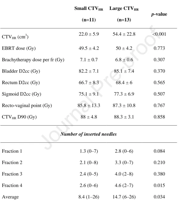
The FIGO staging of the patients was as follows: stages IIA (n=1), IIB (n=4), IIIB (n=4), IIIC1 (n=9; [T2bN1 (n=7), T3bN1 (n=2)]), IIIC2 (n=2; [T1b2N1 (n=1), T2bN1 (n=1)]), IVA (n=3; [T4N0 (n=1), T4N1 (n=2)]), and IVB (n=1; T3aN1M1). Eleven patients had a small CTVHR and 13 had a large CTVHR. The CTVHR D90 and OAR doses were similar
between the two patient groups (Table 1). A higher number of needles was inserted in patients with a large CTVHR compared to those with small CTVHR (average number of total
needles inserted per patient: 14.7 vs. 8.4 needles, respectively; p=0.034). Similarly, average number of needles inserted per BT fraction was also higher in patients with large CTVHR
(mean ± SD [95% confidence interval, CI]: 4.7 ± 1.3 [3.2-4.7] vs. 2.5 ± 1.7 [1.3-3.7],
p=0.015) (Figure 4). The number of needles inserted in each fraction is shown in Figure 4
based on large and small CTVHR.
Among the 24 study participants, needle insertion was avoided in 9 (three with large and six with small CTVHR), 4 (one with large and three with small CTVHR), 2 (both with
small CTVHR), and 2 (both with small CTVHR) patients during the 1st, 2nd, 3rd and 4th BT
fractions, respectively, by using CTpreneedle (Figure 4). Fewer needles were inserted in patients
with small CTVHR, although there was a high intra- (from fraction to fraction) and
inter-patient variation in the number of inserted needles.
Needle dwell intensities
When the dwell intensity of each of the 266 needles was evaluated within the total dwell time of a fraction, the intensity of 11 (4%) needles was 0%, indicating that they were not loaded after insertion. The average dwell intensity of an individual needle was 11 ± 8% (range, 0– 42), and the dwell intensity was >15% in 63 out of 266 needles (Figure 5A). The total contribution of the needles inserted in a fraction was 37.2 ± 19.2% (range, 1.3–84.1) (Figure 5B). The average dwell intensity of needles within a fraction was 1–20%, 20–40%, 40–60%, and >60% in 15 (19.7%), 26 (34.2%), 24 (31.6%), and 11 (14.5%) of the 76 fractions, respectively. The average contribution of the needles to the complete BT treatment was 30.3 ± 18%. The contribution of needles was significantly higher in patients with a large CTVHR
than in those with a small CTVHR (mean ± SD [95% CI]: 40 ± 12% [32–46] vs. 19 ± 18% [7–
31]; p=0.003; Figure S2). The needle dwell intensity of the fractions in which no needle was inserted was accepted as 0%.
In addition, no significant differences in dwell intensity were found between the 10 different needle locations as well as the different grouping of needle locations (among 10 locations, p=0.104; medial vs. lateral, p=0.394; anterior vs. medius vs. posterior, p=0.679; anteromedius vs. posterior, p=0.380; left vs. right, p=0.236).
Needle shifts
Among the 266 needles used, no shift was observed in 85 (32%); however, in the majority of the needles, a shift was noticed (mean shift magnitude: 2.0 ± 2.3 mm [range: 0–10.4; 95% CI: 1.7–2.3]). There was a significant difference between needle locations in terms of shift magnitude (p=0.008), which was being generally greater in the LMP, RLA, RMA, and RMP locations than in the others (Figure 6). Moreover, the magnitude of the shift differed
significantly by the direction of the shift, being greater in the posterior, posterolateral, and posteromedial directions (p=0.008, Figure 6).
Furthermore, we evaluated the frequency of shifts and shift directions based on needle locations and found that shift was less frequent in needles with LLA, LLP, and RLP locations. Shift magnitude was highest in the posterior direction, and a shift toward the posterior direction occurred less frequently (3%). Shifts occurred most frequently toward the posterolateral and posteromedial directions (Figure 7).
There was a significant difference in needle length between needles with and without shift. Needles with a shift were significantly longer (mean needle length 28.6 [95% CI: 27– 30] vs. 18.5 mm [95% CI: 16–20], p<0.0001). Moreover, in 56 needles (21%), the shift magnitude was ≥3.5 mm. The cut-off value of 3.5 mm was chosen as it was at 50% of the distance between the two needles (7 mm). Similarly, needles with a ≥3.5 mm shift were significantly longer than those with <3.5 mm shift (mean needle length 33.0 mm [95% CI: 33–35] vs. 23.3 mm [95% CI: 22–25; p<0.0001; Figure S3).
The ΔLength, the difference between the planned needle insertion length based on CTpreneedle and the actual length of the inserted needle measured on the CTpostneedle, was
assessed. The ΔLength was zero in only five needles (2%), and was generally negative, indicating that the measured needle length was shorter than the planned length. The average
ΔLength was −2.3 ± 3.4 mm, with an average relative value of -9 ± 15% (ΔLength/needle
length; Figure S4). No significant association was found between the relative ΔLength percentage and needle location (p=0.09) or needle length (p=0.085).
Needle insertion complications
None of the study participants had an infection. One patient with a platelet count <80.000/µ L experienced vaginal bleeding after the removal of the needles. The bleeding stopped with tamponade containing tranexamic acid, without causing any hemodynamic instability. No needle intrusion into the other OARs or an organ perforation was observed.
Discussion
In this study, we investigated the feasibility and added value of CT guidance in addition to the MRIpostEBRT for needle insertion during IS-BT application, with regard to: IS-BT
indication adaptation, inserted but unloaded needle frequency, complications caused by needle insertion, and the contribution of needle to the treatment. Moreover, we evaluated the shift in the needles after insertion.
In general, the IS-BT indication, needle channels, and the needle insertion length are determined on the basis of MRIpostEBRT as a guide for the first fraction of BT. The indication
and planning of needle insertion for the subsequent BT fractions are defined by the shortcomings of the first/previous fractions.9, 11 Among the 24 patients in this study, needle insertion was indicated in 15 based on the MRpostEBRT; in 5 of these 15 patients, the IS-BT
indication disappeared in at least one of subsequent fractions because it was possible to fulfill the EMBRACE II planning protocol without needles, based on the findings from the CTpreneedle. Conversely, indications for needle insertion emerged in nine patients due to
tandem/ovoid positioning, uterus rotation after IC application, and/or close proximity of an OAR to the target on the day of fraction, whereas no indication was foreseen based on the MRIpostEBRT in these patients.
A different strategy of CT-guided IS-BT was previously proposed by Liu et al.17 In their study, the tandem was inserted under ultrasound guidance followed by the free-hand preliminary insertion of needles based on the MRIpostEBRT. After needle insertion, CT imaging
was performed, and the position of the needles was examined. The depth and directions of the needles were adjusted on the basis of repeated multiple CT scans until optimal positioning was achieved, with a mean CT scan of 2.6 ± 1.3 for each needle placement in their patient population. However, of the 955 needles inserted, 26 (2.76%) resulted in a perforation of the mesentery and/or intestine.17 Moreover, more severe and frequent OAR injuries during perineal IS-BT have been reported.18 In 28 of the 42 patients (67%), radiological evidence of needle penetration into at least one pelvic organ was observed that resulted in acute toxicities, including hematuria, perineal infections, and vaginal bleeding in nine patients.18 In this study, only one patient with thrombocytopenia had minor vaginal bleeding after needle removal. Needle intrusion into the OARs was not observed in any of the patients. Furthermore, no repeated CT scans were required with the proposed technique to adjust the needles.
A crucial issue in IS-BT pertains to the inserted but unloaded needles, which may increase the risk of the aforementioned complications. In a study by Smolic et al., one of every five (20%) needles inserted was not loaded after insertion,11 whereas in this study, this frequency was much smaller (11/266 needles [4%]). A closer examination of patients with unloaded needles revealed that they had been treated within the first 3 months following IS-BT implementation in XXX institution, and possibly reflected the learning curve. The number of needles inserted was not stable from fraction to fraction in any of the patients due to OAR movement and/or IC-BT applicator placement. All IS-BTs were performed by the same radiation oncologist (thereby eliminating inter-applier variability). Therefore, the
needle use due to the circumstances pertaining to that BT fraction under CT guidance – the so-called adaptive CT-guided IS-BT.
As the indication was constantly updated using the CTpreneedle for each fraction in this
study, the needles were used more efficiently than in previous studies. The average dwell intensity of the total needles inserted within a fraction was reported as 22%, and exceeded 30% for 13 of 66 fractions (20% of the fractions) in the study by Smolic et al.,11 whereas it was 37%, and exceeded 30% in 45 out of 76 fractions (59% of the fractions) in this study. Furthermore, the average dwell intensity of individual needles was higher in this study (11%) than that (7%) in a previously reported study by Nomden et al.9
The shift in the IC applicator is a well-known problem during BT, and causes substantial changes in both OAR and target-related dose-volume histogram parameters.19 Nonetheless, to our knowledge, a shift in the needles has not been evaluated so far. The IC applicator generally shifts in the anterior direction and less frequently in the lateral–medial directions; the needle shift direction in this study was mostly toward the posterolateral and posteromedial directions. In addition, we observed that the shift magnitude was greater in needles with longer insertion lengths. The mean shift magnitude was 2.0 ± 2.3 mm and did not necessitate needle position adjustment by reinsertion or subsequent repeated CT scanning in any patient.
A limitation (and, possibly, a strength) of this study was the use of CT, instead of MRI, for BT planning. Despite the expansion in the use of MRI for BT, most centers still use CT-based BT planning. In addition, MRI and CT were comparable with each other in terms of the CTVHR D90 and CTVIR D90 dose coverage, despite the better visualization of OARs
and tumor boundaries on MRI.20-22 Better reconstruction of the applicator and the inserted needles was possible with CT. Furthermore, obtaining two MRIs, as MRIpreneedle and
MRIpostneedle, in each BT fraction would have been too time consuming and labor intensive
and would require an MR-compatible obturator needle. Moreover, as the total time before treatment application would be too long, the shift in the applicator would be greater, which could possibly result in negative consequences with regard to the reliability and value of the preneedle imaging as a guide for needle insertion. A practical solution would be to perform CTpreneedle for needle insertion guidance and, subsequently, MRIpostneedle for treatment planning
in logistically equipped centers. Deformable image registration of MRIpostEBRT with planning
CT taken after applicator insertion is also a promising option for a more accurate target delineation, especially in centers without MRI compatible applicators.23-24
Conclusion
The adaptive CT-guided IS-BT application was found to be feasible and resulted in fewer unloaded needle insertions and complications. As the needle insertion indication was re-evaluated before each fraction using CT imaging that was performed after the IC applicator application, the needles were used more efficiently with higher dwell intensities. Moreover, needle shifts were frequent and mostly occurred in the posterolateral and posteromedial directions and were more pronounced with larger insertion lengths. However, needle reinsertion was not required with the method that was proposed in this study.
References
1. Fokdal L, Sturdza A, Mazeron R, et al. Image guided adaptive brachytherapy with combined intracavitary and interstitial technique improves the therapeutic ratio in locally advanced cervical cancer: Analysis from the retroEMBRACE study. Radiother Oncol. 2016;120:434-440.
2. Kirisits C, Lang S, Dimopoulos J, Berger D, Georg D, Potter R. The Vienna applicator for combined intracavitary and interstitial brachytherapy of cervical cancer: design, application, treatment planning, and dosimetric results. Int J Radiat Oncol Biol Phys. 2006;65:624-630.
3. Anderson C, Lowe G, Wills R, et al. Critical structure movement in cervix brachytherapy. Radiother Oncol. 2013;107:39-45.
4. Barnes EA, Thomas G, Ackerman I, et al. Prospective comparison of clinical and computed tomography assessment in detecting uterine perforation with intracavitary brachytherapy for carcinoma of the cervix. Int J Gynecol Cancer. 2007;17:821-826.
5. Segedin B, Gugic J, Petric P. Uterine perforation - 5-year experience in 3-D image guided gynaecological brachytherapy at Institute of Oncology Ljubljana. Radiol Oncol. 2013;47:154-160.
6. Onal C, Guler OC, Dolek Y, Erbay G. Uterine perforation during 3-dimensional image-guided brachytherapy in patients with cervical cancer: Baskent University experience. Int J Gynecol Cancer. 2014;24:346-351.
7. Bahadur YA, Eltaher MM, Hassouna AH, Attar MA, Constantinescu C. Uterine perforation and its dosimetric implications in cervical cancer high-dose-rate brachytherapy. J Contemp Brachytherapy. 2015;7:41-47.
8. Tsai YL, Yu PC, Lui LT, Shaw S, Wu CJ. Small bowel dose in subserosal tandem insertion during cervical cancer brachytherapy. Med Dosim. 2020;45:e1-e9.
9. Nomden CN, de Leeuw AA, Moerland MA, Roesink JM, Tersteeg RJ, Jurgenliemk-Schulz IM. Clinical use of the Utrecht applicator for combined intracavitary/interstitial
brachytherapy treatment in locally advanced cervical cancer. Int J Radiat Oncol Biol Phys. 2012;82:1424-1430.
10. Jurgenliemk-Schulz IM, Tersteeg RJ, Roesink JM, et al. MRI-guided treatment-planning optimisation in intracavitary or combined intracavitary/interstitial PDR brachytherapy using tandem ovoid applicators in locally advanced cervical cancer. Radiother Oncol. 2009;93:322-330.
11. Smolic M, Sombroek C, Bloemers M, van Triest B, Nowee ME, Mans A. Needle use and dosimetric evaluation in cervical cancer brachytherapy using the Utrecht applicator. Radiother Oncol. 2018;126:411-416.
12. Haie-Meder C, Potter R, Van Limbergen E, et al. Recommendations from Gynaecological (GYN) GEC-ESTRO Working Group (I): concepts and terms in 3D image based 3D treatment planning in cervix cancer brachytherapy with emphasis on MRI assessment of GTV and CTV. Radiother Oncol. 2005;74:235-245.
13. Potter R, Haie-Meder C, Van Limbergen E, et al. Recommendations from gynaecological (GYN) GEC ESTRO working group (II): concepts and terms in 3D image-based treatment planning in cervix cancer brachytherapy-3D dose volume parameters and aspects of 3D image-based anatomy, radiation physics, radiobiology. Radiother Oncol. 2006;78:67-77.
14. Hellebust TP, Kirisits C, Berger D, et al. Recommendations from Gynaecological (GYN) GEC-ESTRO Working Group: considerations and pitfalls in commissioning and applicator reconstruction in 3D image-based treatment planning of cervix cancer brachytherapy. Radiother Oncol. 2010;96:153-160.
15. Dimopoulos JC, Petrow P, Tanderup K, et al. Recommendations from Gynaecological (GYN) GEC-ESTRO Working Group (IV): Basic principles and parameters for MR imaging within the frame of image based adaptive cervix cancer brachytherapy. Radiother Oncol. 2012;103:113-122.
16. Berger T, Seppenwoolde Y, Potter R, et al. Importance of Technique, Target Selection, Contouring, Dose Prescription, and Dose-Planning in External Beam Radiation Therapy for Cervical Cancer: Evolution of Practice From EMBRACE-I to II. Int J Radiat Oncol Biol Phys. 2019;104:885-894.
17. Liu ZS, Guo J, Zhao YZ, et al. Computed Tomography-Guided Interstitial Brachytherapy for Locally Advanced Cervical Cancer: Introduction of the Technique and a Comparison of Dosimetry With Conventional Intracavitary Brachytherapy. Int J Gynecol Cancer. 2017;27:768-775.
18. Mendez LC, Lang P, Patel C, et al. A prospective analysis of catheter complications for gynecological cancers treated with interstitial brachytherapy in the 3D era. Brachytherapy. 2019;18:44-49.
19. Shi D, He MY, Zhao ZP, et al. Utrecht Interstitial Applicator Shifts and DVH Parameter Changes in 3D CT-based HDR Brachytherapy of Cervical Cancer. Asian Pac J Cancer Prev. 2015;16:3945-3949.
20. Krishnatry R, Patel FD, Singh P, Sharma SC, Oinam AS, Shukla AK. CT or MRI for image-based brachytherapy in cervical cancer. Jpn J Clin Oncol. 2012;42:309-313.
21. Viswanathan AN, Dimopoulos J, Kirisits C, Berger D, Potter R. Computed tomography versus magnetic resonance imaging-based contouring in cervical cancer
brachytherapy: results of a prospective trial and preliminary guidelines for standardized contours. Int J Radiat Oncol Biol Phys. 2007;68:491-498.
22. Eskander RN, Scanderbeg D, Saenz CC, Brown M, Yashar C. Comparison of computed tomography and magnetic resonance imaging in cervical cancer brachytherapy target and normal tissue contouring. Int J Gynecol Cancer. 2010;20:47-53.
23. Dyer BA, Yuan Z, Qiu J, et al. Clinical feasibility of MR-assisted CT-based cervical brachytherapy using MR-to-CT deformable image registration. Brachytherapy. 2020;19(4):447-456.
24. Tait LM, Hoffman D, Benedict S, Valicenti R, Mayadev JS. The use of MRI deformable image registration for CT-based brachytherapy in locally advanced cervical cancer. Brachytherapy. 2016;15(3):333-340.
Figure Captions
Figure 1. The decision tree and clinical workflow in interstitial intracavitary brachytherapy
(IS-ICBT). OAR, organ at risk; CT, computed tomography; EBRT, external-beam radiotherapy
Figure 2. The CTpreneedle (with tandem, without needle) and CTpostneedle in a patient (with
needle). The needle channel and insertion length were decided using CTpreneedle and based on
applicator and OAR positioning on the day of the fraction. CTpostneedle was performed after
needles were inserted and used for interstitial intracavitary brachytherapy (IS-ICBT) planning. The shift of the needle from the needle channel axis can be seen on CTpostneedle
image.
Figure 3. The determination of the magnitude and direction of the needle shift using the axis
of the corresponding needle channel.
Figure 4. The number of needles inserted per fraction. *Patients treated with three fractions
of brachytherapy (BT); others received four fractions of BT.
Figure 5. The dwell intensity of the individual and total needles used in a fraction. The
values are sorted from the smallest to the largest. A: the dwell intensity of each of the 266 needles (channel dwell time of each needle as a percentage of the total dwell time of a fraction). B: the average dwell intensity of the total needles (the average ratio of needle channel dwell times as a percentage of the total dwell time of a fraction) used in 76 brachytherapy (BT) fractions. The red columns represent the dwell intensity of needles, whereas the blue columns represent the summed dwell intensities of the other parts, including the canal, tandem, and ovoids.
Figure 6. The boxplot of needle shift magnitude (mm) per needle location and direction of a
shift. A red reference line was placed to indicate the 3.5 mm value on the Y-axis, which represents 50% of the normal distance between the two needle channels (i.e., 7 mm).
Figure 7. The frequencies of shifts and shift direction per needle location. In the “No shift”
and the “Shift direction” columns, the increase in frequency is indicated by a change in the color of the cells from white to green and from white to red, respectively.
Tables
Table 1. Comparison of dose-volume histogram parameters (mean ± SD) and average (min–max)
number of needles inserted between patients with small (<30 cm3) and large (≥30 cm3) CTVHR based
on the volume in the first fraction
Small CTVHR (n=11) Large CTVHR (n=13) p-value CTVHR (cm 3 ) 22.0 ± 5.9 54.4 ± 22.8 <0.001 EBRT dose (Gy) 49.5 ± 4.2 50 ± 4.2 0.773 Brachytherapy dose per fr (Gy) 7.1 ± 0.7 6.8 ± 0.6 0.307 Bladder D2cc (Gy) 82.2 ± 7.1 85.1 ± 7.4 0.370 Rectum D2cc (Gy) 66.7 ± 8.3 68.4 ± 6 0.565 Sigmoid D2cc (Gy) 75.1 ± 9.1 77.3 ± 6.9 0.507 Recto-vaginal point (Gy) 85.8 ± 13.3 87.3 ± 10.8 0.767 CTVHR D90 (Gy) 88 ± 4.8 88.3 ± 3.1 0.858
Number of inserted needles
Fraction 1 1.3 (0–7) 2.8 (0–6) 0.084 Fraction 2 2.1 (0–8) 3.3 (0–7) 0.210 Fraction 3 2.4 (0–5) 4.0 (2–8) 0.380 Fraction 4 2.6 (0–6) 4.6 (2–7) 0.015 Average 8.4 (1–26) 14.7 (6–26) 0.034 CTVHR, high-risk clinical target volume; EBRT, external-beam radiotherapy