Analysis of Charge Transfer for in Situ Li Intercalated Carbon
Nanotubes
⊥Kuldeep Rana,
†Gokce Kucukayan-Dogu,
‡H. Sener Sen,
§Chris Boothroyd,
∥Oguz Gulseren,
§and Erman Bengu*
,††Department of Chemistry, Bilkent University, 06800 Ankara, Turkey
‡Institute of Engineering and Science, Materials Science and Nanotechnology Graduate Program, Bilkent University, 06800 Ankara,
Turkey
§Department of Physics, Bilkent University, 06800 Ankara, Turkey ∥Forschungszentrum Julich, D-52425 Julich, Germany
*
S Supporting InformationABSTRACT: Vertically aligned carbon nanotube (VA-CNT) arrays have been synthesized with lithium (Li) intercalation through an alcohol-catalyzed chemical vapor deposition technique by using a Li-containing catalyst. Scanning electron microscopy images display that synthesized carbon nanotubes (CNTs) are dense and vertically aligned. The effect of the Li-containing catalyst on VA-CNTs has been studied by using Raman spectroscopy, X-ray photoelectron spectroscopy (XPS), and electron energy loss spectroscopy (EELS). XPS results show the change in binding energy of Li 1s and C 1s peaks, which indicates that Li is inserted in VA-CNTs during growth. Analysis of Raman
spectra reveals that the G-band profile of CNTs synthesized with the Li-containing catalyst is shifted, suggesting an electronic interaction between Li and neighboring C atoms of the CNTs. The EELS spectra of the C K edge and Li K edge from CNTs also confirmed that Li is inserted into CNTs during synthesis. We have performed ab inito calculations based on density functional theory for a further understanding of the structural and electronic properties of Li intercalated CNTs, especially addressing the controversial charge-transfer state between Li and C.
■
INTRODUCTIONCarbon-based materials are prime candidates for electrode applications in lithium (Li)-ion batteries due to their structural stability and high capacity.1−9 Improvements in the Li adsorption capacity of the carbon nanotube (CNT)-based anodes have been reported with the help of doping, functionalizing, defect engineering, and hybridizing CNTs with fullerenes.10Further enhancements are also reported by ex situ doping of CNTs with Li6 and using vertically aligned carbon nanotube (VA-CNT) arrays as electrodes.11
Despite the volume of experimental and theoretical works on electronic and structural changes induced by the intercalation of Li in graphite12−16 and in CNTs,5,17,18 charge transfer between Li and the hexagonal carbon network remains a subject of controversy. Results of some computational studies on intercalation of alkali metals in graphite indicate complete charge transfer,14contrary to others suggesting a partial charge transfer.19−21X-ray photoelectron spectroscopy (XPS)22,23and electron energy loss spectroscopy (EELS)24have been mainly used to probe the nature of the charge transfer experimentally and have given inconsistent results.
Recently, there were few reports of CNTs and carbon nanostructures grown on Li-containing compounds;9,25,26
however, incorporation of Li to the carbon network has not been examined in detail. In this study, we have demonstrated in situ Li intercalation of CNTs during their synthesis. Scanning/ transmission electron microscopy (S/TEM), EELS, XPS, and Raman spectroscopy were used to confirm the insertion of Li in the CNT network. Following these results, we have also performed ab initio density functional theory (DFT) calculations on various geometries to understand the energeti-cally stable configurations for Li insertion and the resulting charge distribution. To address the existing controversy over charge transfer, we have employed orders of magnitude denser meshes than usual to achieve reliable convergence. To the best of our knowledge, this is the first attempt where in situ Li intercalation of VA-CNTs is successfully demonstrated, and in addition, both experimental and ab initio analysis have been used for correlating the charge transfer.
Received: February 10, 2012
Revised: April 24, 2012
Published: April 30, 2012
■
EXPERIMENTAL METHODSTwo types of catalyst solutions were prepared. Thefirst was a Li-containing catalyst solution prepared by dissolving Al-(NO3)3·9H2O, Co(NO3)2·6H2O, and LiNO3 (molar ratio of
Al/Co/Li is 1/1/1.4) in 10 mL of ethanol, and the second was with Al(NO3)3·9H2O and Co(NO3)2·6H2O (molar ratio of Al/
Co is 1/1). These solutions were coated onto the oxidized Si(100) substrates. Next, the substrates were treated in a furnace by alcohol-catalyzed chemical vapor deposition (ACCVD), which has two steps: (a) reduction and (b) reaction where ethanol was introduced to facilitate CNT growth.27A summary of the experiments is given in Table 1.
■
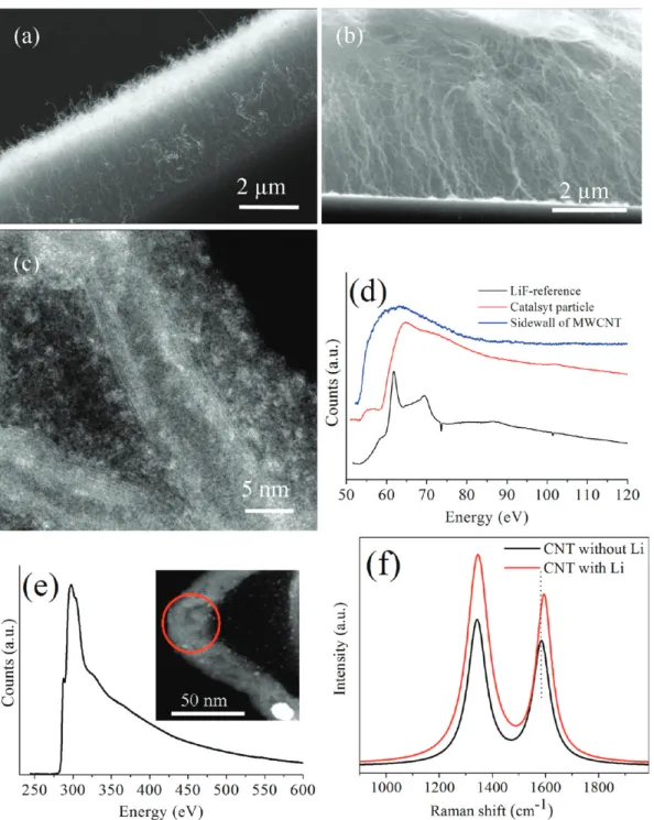
RESULTS AND DISCUSSIONScanning electron microscopy (SEM) images of VA-CNTs from Set 3 and Set 1 are shown in Figure 1a,b. These cross-sectional views show that CNTs are aligned perpendicular to the surface of the substrates. The morphology of individual CNTs grown with Li (Set 1) was further investigated by S/ TEM (Figure 1c). The length of the CNTs was measured to be ∼5 μm, and the diameters were between 10 and 20 nm.
The EEL spectra of Li K and C K edges are shown in Figure 1d,e, obtained from the CNTs grown in Set 1, respectively. The Li K edge is observed at 55.6 eV, which is shifted by 0.6−0.8 eV with respect to the metallic Li K edge, reported at 5528and 54.8 eV.12 This shift in the Li K edge is expected due to charge transfer from the Li to the C atoms. Hightower et al.24 also reported a 0.2 eV shift for bulk LiC6.
The C K edge has a sharp edge just below the main absorption threshold (Figure 1e). This is characteristic of the excitation of electrons from the C 1s orbital to states above the Fermi level, suggesting that graphite-like sheets are present in the sample. In our study, we observed that this edge is centered about 285.5 eV (π*), which corresponds to the unoccupied antibondingπ* states of sp2-hybridized C. This edge is reported to be at 285 eV for pure CNTs29and at 285.5 eV for CNTs intercalated by alkali metals.30,31Hence, our measurements are in agreement with the earlier reports and confirm the presence of Li in CNTs.
High-resolution Raman spectra were also analyzed for Set 1 and Set 3 (Figure 1f). The G band (E2gmode) corresponding
to in-plane vibration of C atoms32,33was observed at 1594 and 1582 cm−1for CNTs grown in Set 1 and Set 3, respectively. However, the D band for both samples, which is attributed to disorder and defects in the CNTs,33was observed at the same wavenumber of 1344 cm−1 and did not get affected by the presence of Li. Several studies also reported a shift toward higher wavenumbers for the G band (11 cm−1in this study); this is due to the insertion of the Li atom between the layers and charge transfer from Li to the C matrix.34,35
TEM and Raman spectra provide strong support for the presence of Li in the CNTs; nevertheless, an XPS analysis was conducted. XPS spectra for Li 1s and C 1s peaks are shown in
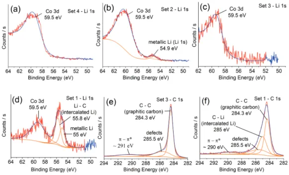
Figure 2, and the binding energies (EB) of the peaks are tabulated in Table 2. To understand the chemical state of Li, Set 2 and Set 4 samples were synthesized. An XPS spectrum from Set 4 is shown in Figure 2a and has a broad asymmetric peak centered on 59.5 eV corresponding to Co 3d.36In the XPS spectrum from Set 2, a second peak appears at 54.9 eV corresponding to metallic Li37(Figure 2b). This shows that the Li and Co on the substrates after the reduction step were metallic.
XPS analysis has been also carried on VA-CNTs synthesized in Set 1 and Set 3 to confirm the chemical state of Li. Figure 2c shows the Co 3d peak centered at 59.5 eV for Set 3. For Set 1 (Figure 2d), three peaks were found around 55 eV (metallic Li), 55.8 eV (intercalated Li), and 59.5 eV (Co 3d). The Li 1s peak for the intercalated Li in the LiC6compound was reported at 56 eV with a shift toward higher EB compared to metallic
Li.38 This shift is due to charge transfer from Li to the C matrix.38In our study, when we compare the EBof Li 1s for Set
1 (55.8 eV) with Set 2 (54.9 eV), there is a shift toward higher EB, which can be suggested as another evidence for Li intercalation during CNT growth (Set 1).
A detailed analysis of the C 1s peak was also conducted to confirm Li intercalation. The shape of the C 1s peak from Set 1 (Figure 2e) is different than that for the CNTs in Set 3 (Figure 2f). After deconvolution of the C 1s peak from Set 3, the main peak (graphitic C) appears at 284.3 eV (fwhm 0.7 eV) with a broad component at 285.5 eV due to C−H bonding39,40 (Figure 2e). The deconvolution of C 1s peak from Set 1 results in multiple peaks; a main component at 284.3 eV and a broader one at 285 eV (Figure 2f). The peak at 285 eV corresponds to the Li intercalated CNTs and shifted toward the higher EBside compared with the component at 284.3 eV, which is the BE of the C 1s of CNTs without Li. Generally, C 1s peaks between 285 and 285.2 eV are attributed to Li intercalated C, such as LiC6and LiC2.
41
Besides, the broader appearance of this peak with respect to that for graphitic C (284.3 eV) was considered to be due to charge redistribution on C induced by Li.39,42,43 XPS analyses results for the ex situ intercalation attempt are provided in the Supporting Information.
We have also performed first-principles plane-wave calcu-lations44−46 within DFT by the projector-augmented wave (PAW) potentials.47,48 Both the local density approximation (LDA)49and the generalized gradient approximation (GGA)50 were employed for the description of the exchange-correlation potential. We used various configurations based on a bilayer graphene system with AA (8 initial configurations) and AB (12 initial configurations) stacking to understand the Li interaction. The large supercell is set as a 6× 6 bilayer graphene in plane with around 15 Å of vacuum in the perpendicular direction. Accordingly, we have used a 7× 7 × 1 Monkhorst−Pack51 k-point mesh for sampling the Brillouin zone. All edge C atoms furthest away from the Li atom are frozen in order to keep the 3.34 Å distance between the graphene layers, but allowing the relaxation of atoms in the vicinity of Li. All Li/bilayer graphene configurations were optimized, and the corresponding binding energies of the Li were calculated to understand how Li binds with CNTs. Even though the resulting binding energies were different, their order and corresponding physical picture were similar regardless of the stacking and functionals used. Hence, we only discussed the results from AA stacking with the LDA potential throughout. Furthermore, for resolving the con-troversial discussion for charge transfer, we have investigated the charge densities of the systems from the converged Table 1. Summary of Experiments
experiment catalyst ACCVD run after ACCVD
Set 1 Li-containing Co reduction + reaction CNT Set 2 Li-containing Co reduction
Set 3 Co reduction + reaction CNT
calculations using Bader analysis.52,53 All the results can be described in three groups as follows:
Adsorption. We have three possible adsorption sites; top (on top of a C atom), hollow site (above the center of a hexagon), and the bridge site (above the bond between two C's) as labeled by 1, 2, and 3 in Figure 3a, respectively. After geometry relaxation, we observed that the Li ended up∼2.2 Å away from the nearest C and makes a bond accordingly. Of these adsorption geometries, the most stable site energetically (highest binding energy) is adsorption above the center of a hexagon with the binding energy of 2.29 eV, while the other sites have binding energies of around 1.9 eV.
Substitution. We tried Li substitution geometries by removing one C and substituting it with Li. Understandably,
a very tight geometry is present in terms of bond lengths; that is, C−C is 1.42 Å, whereas the Li−C bond distance is around 2.2 Å. Because of this, we have also considered a double C vacancy on graphene. Substitutional Li could then be introduced as there is more space available. Nevertheless, in both of the cases, the planar geometry is stretched to accommodate the Li. The resulting distortion of the planar structure of graphene is relaxed by Li wandering in between the graphene layers. There, Li positions such that it optimizes the Li−C length to around ∼2.2 Å in the defective graphene. The binding energy with respect to the corresponding defective graphene layer is 3.54 and 3.29 eV for single and double vacancy cases, respectively.
Figure 1.Cross-sectional SEM images of VA-CNTs from (a) Set 3 and (b) Set 1. (c) S/TEM image of a CNT from Set 1. EEL spectra of Set 1 for (d) Li K edge and (e) C K edge (inset shows where the spectrum is taken from). (f) Raman spectra from Set 1 and Set 3.
Intercalation. We have checked possible different Li sites between the two graphene layers. As described earlier, Li tries to optimize the Li−C length to ∼2.2 Å; hence, it prefers to sit on a hollow site where there is more room for an interstitial
atom. The binding energy is∼3.01 eV in these cases. Besides, the projected density of states (PDOS) for these cases is shown in Figure 3b.
Energy minimization calculations resulted in eight different final adsorption configurations, and the binding energies, Li−C bond distances, and total charge transfer from Li to the carbon network are listed in Table 3. LDA and GGA calculations show
that it is energetically favorable for a Li atom to go in between the layers. The most stable case labeled as mid hollow is shown in Figure 3c. In this configuration, the Li atom tends to stay in the middle of the hexagons of two layers (Li−C bond length ∼ 2.3 Å). However, as shown in Table 3, the binding energies for the intercalated Li starting from substituted Li (Figure 3d) are larger, since these were calculated with respect to the defective graphene bilayer system.
The last column of Table 3 shows the charge transferred from Li to the graphitic system, which is calculated using the Bader analysis.52,53It is essential to calculate this charge transfer
Figure 2.Li 1s XPS spectra of (a) Set 4, (b) Set 2, (c) Set 3, and (d) Set 1. C 1s XPS spectra of (e) Set 3 and (f) Set 1.
Table 2.EBPosition and fwhm for C 1s and Li 1s XPS Peaks
samples EBLi 1s (eV) EBC 1s (eV)
Set 1 55.8 284.3(0.9) 285.0(1.9)
Set 2 54.9
Set 3 284.3(0.7) 285.5(2.8)
Figure 3.(a) Possible Li adsorption sites; top (1), hollow (2), and bridge (3) for a 6× 6 unit cell. (b) PDOS for Li intercalated cases shown in (c) and (d). Dotted line indicates the Fermi level. Top and side views of the optimized geometry and the charge density of (c) Li intercalated bilayer graphene and (d) a similar system, but starting from Li substitution to a C site on top layer.
Table 3. Binding Energies, Li−C Bond Distances, and Total Charge Transfer from Li to C Network for Li-Doped AA Stacking Bilayer Resulted from LDA Calculations
adsorption geometry
binding energy
(eV)a distance (Å)Li−C bond
total charge transferred to C atoms (e) outer top 1.93 1.99 0.9 outer bridge 1.96 2.08 0.9 outer hollow 2.29 2.21 0.88 mid top 2.6 2.01 0.84 mid bridge 2.63 2.09 0.84 mid hollow 3.01 2.3 0.85 substituted: single C vacancy 3.54 2.27 0.84 substituted: double C vacancy 3.29 2.12 0.86 aE
binding= Etotal − (Ebi‑graphene+ nLi× μLi). Etotal: total energy of the
relaxed composite system. Ebi‑graphene: energy of graphitic system (i.e.,
bilayer graphene or bilayer graphene with vacancies). nLi: number of Li
accurately in order to address the controversial results in the literature. Note that it is easy to associate the charge with the specific atom if the computational method is based on the local basis set, but generally, this approach is less accurate. On the other hand, one can systematically control the accuracy within the calculation using the plane-wave basis set, which requires the definition of a volume around the atom, including all the charge associated with it, a nontrivial task. For example, we used Bader analyses of a simple graphene layer as a benchmark: while the charge on the carbon atoms for a 1× 1 unit cell was found to be 4.00 e, itfluctuated between 3.99 and 4.01 e for a 6 × 6 unit cell. Another approach for calculating the charge of each atom from PDOS suffers from similar issues as well. Furthermore, in order to describe the charge transfer, the difference of charges before and after Li intercalation, one has to describe the charge around each atom very accurately. In this regard, we have examined all of the computational parameters in detail using the graphene and LiC6systems. For instance, we
have used as much as 10 times denser grids than the ones commonly used for accurate calculations in the literature for charge density calculations. Ourfinal results clearly show that almost 0.86 electrons from the Li atom are transferred to neighboring C atoms, leaving a positively charged Li core behind. In Figure 3c,d, the transferred charge is displayed by presenting the difference charge density, calculated by subtracting the charge densities of the graphitic system and the Li atom from the charge density of the intercalated system. For the perfect intercalated case, it can be depicted that all atoms in the graphitic hexagons share the incoming electron from the Li, as shown in Figure 3c. The extra charge is distributed symmetrically, and this electron tends to accom-modate in the form of the pz orbital of C atoms. For the
defective intercalated cases, the extra charge is accommodated more around the missing C atoms to compensate for the dangling bonds (Figure 3d).
■
CONCLUSIONSIn this study, we have successfully intercalated Li into VA-CNTs during growth. The XPS and EELS spectra show the presence of Li. The insertion of Li in VA-CNTs was confirmed by investigating the XPS spectra through the change in EBfor Li 1s and C 1s. The charge transfer to the C lattice is another indication for Li in between graphitic layers, and this is also demonstrated by the upshift in the G band in Raman spectra. We have also performedfirst-principles calculations showing Li atoms having a strong tendency for intercalation. Our calculations revealed a transfer of almost one electron (0.86 e) from Li to the neighboring C network, in good agreement with the experimental results. Our study shows that pre-doping of CNTs with Li during growth is possible, which will be an efficient anode material in lithium-ion batteries, improving battery performance by reducing capacity loss in thefirst cycle and rate capability.
■
ASSOCIATED CONTENT*
S Supporting InformationXPS spectra of additional experiments. This material is available free of charge via the Internet at http://pubs.acs.org.
■
AUTHOR INFORMATIONCorresponding Author
*Phone: +90 312 290 21 53. Fax: +90 312 266 40 68. E-mail: [email protected].
Author Contributions
⊥The manuscript was written through contributions from all
authors. All authors have given approval for thefinal version of the manuscript.
Notes
The authors declare no competingfinancial interest.
■
ACKNOWLEDGMENTSWe thank Dr. Li Kun at KAUST for the use of TEM facilities and the Scientific and Technological Research Council of Turkey (Tubitak) forfinancial support.
■
REFERENCES(1) Basu, S. Rechargeable battery. U.S. Patent 4,304,825, December 8, 1981.
(2) Meunier, V.; Kephart, J.; Roland, C.; Bernholc, J. Phys. Rev. Lett. 2002, 88, 0755061−0755064.
(3) Che, B.; Lakshmi, B.; Fisher, E. R.; Martin, C. R. Nature 1998, 393, 346−349.
(4) Liu, Y.; Zheng, H.; Liu, X. H.; Huang, S.; Zhu, T.; Wang, J.; Kushima, A.; Hudak, N. S.; Huang, X.; Zhang, S.; Mao, S. X.; Qian, X.; Li, J.; Huang, J. Y. ACS Nano 2011, 5, 7245−7253.
(5) Shimoda, H.; Gao, B.; Tang, X. P.; Kleinhammes, A.; Fleming, L.; Wu, Y.; Zhou, O. Phys. Rev. Lett. 2001, 88, 0155021−0155024.
(6) Yang, Z. H.; Wu, H. Chem. Phys. Lett. 2001, 343, 235−240. (7) Maurin, G.; Henn, F.; Simon, B.; Colomer, J.-F.; Nagy, J. B. Nano Lett. 2001, 1, 75−79.
(8) Lee, Y. T.; Yoon, C. S.; Sun, Y. K. J. Power Sources 2005, 139, 230−234.
(9) Rana, K.; Sil, A.; Ray, S. Mater. Chem. Phys. 2010, 120, 484−489. (10) Okada, S.; Saito, S.; Oshiyama, A. Phys. Rev. Lett. 2001, 86, 3835−3838.
(11) Welna, D. T.; Qu, L.; Taylor, B. E.; Dai, L.; Durstock, M. F. J. Power Sources 2011, 196, 1455−1460.
(12) Wang, F.; Graetz, J.; Moreno, M. S.; Ma, C.; Wu, L.; Volkov, V.; Zhu, Y. ACS Nano 2011, 5, 1190−1197.
(13) Kganyago, K. R.; Ngoepe, P. E. Phys. Rev. B 2003, 68, 2051111− 20511116.
(14) Holzwarth, N. A. W.; Louie, S. G.; Rabii, S. Phys. Rev. B 1983, 28, 1013−1025.
(15) Hartwigsen, C.; Witschel, W.; Spohr, E. Phys. Rev. B 1997, 55, 4953−4959.
(16) Khantha, M.; Cordero, N. A.; Molina, L. M.; Alonso, J. A.; Girifalco, L. A. Phys. Rev. B 2004, 70, 1254221−1254227.
(17) Durgun, E.; Dag, S.; Bagci, V. M. K.; Gulseren, O.; Yildirim, T.; Ciraci, S. Phys. Rev. B 2003, 67, 2014011−2014014.
(18) Nishidate, K.; Hasegawa, M. Phys. Rev. B 2005, 71, 2454181− 2454186.
(19) Benedek, R.; Smith, A. P.; Yang, L. H. Phys. Rev. B 1994, 49, 7786−7789.
(20) Rytkonen, K.; Akola, J.; Manninen, M. Phys. Rev. B 2007, 75, 0754011−0754019.
(21) Chan, T. J.; Neaton, B.; Cohen, M. L. Phys. Rev. B 2008, 77, 235430−23543012.
(22) Mansour, A.; Schnatterly, S. E.; Ritsko, J. J. Phys. Rev. Lett. 1987, 58, 614−617.
(23) Balasubramanian, M.; Johnson, C. S.; Cross, J. O.; Seidler, G. T.; Fister, T. T.; Stern, E. A.; Hamner, C. S.; Mariager, O. Appl. Phys. Lett. 2007, 91, 031904−031907.
(24) Hightower, A.; Ahn, C. C.; Fultz, B.; Rez, P. Appl. Phys. Lett. 2000, 77, 238−240.
(26) Rana, K.; Sil, A.; Ray, S. Adv. Mater. Res. 2009, 67, 197−202. (27) Baykal, B.; Ibrahimova, V.; Er, G.; Bengu, E.; Tuncel, D. Chem. Commun. 2010, 46, 6762−6764.
(28) Liu, D.-R.; Williams, D. B. Philos. Mag. 1986, 53, L123−L128. (29) Xu, Y. J.; Liu, X.; Cui, G.; Zhu, B.; Weinberg, G.; Schlogl, R.; Maier, J.; Su, D. S. ChemSusChem 2010, 3, 343−349.
(30) Liu, X.; Pichler, T.; Knupfer, M.; Fink, J. Phys. Rev. B 2003, 67, 125403−125411.
(31) Cupolillo, A.; Giallombardo, C.; Papagno, L. Surf. Sci. 2007, 601, 2828−2831.
(32) Nemanich, R. J.; Solin, S. A.; Guerard, D. Phys. Rev. B 1977, 16, 2965−2972.
(33) Eklund, P. C.; Holden, J. M.; Jishi, R. A. Carbon 1995, 33, 959− 972.
(34) Bendiab, N.; Anglaret, E.; Bantignies, J.-L.; Zahab, A.; Sauvajol, J. L.; Petit, P.; Mathis, C.; Lefrant, S. Phys. Rev. B 2001, 64, 245424− 245430.
(35) Claye, A. S.; Nemes, N. M.; Janossy, A.; Fischer, J. E. Phys. Rev. B 2000, 62, 4845−4848.
(36) Strydom, A.; Strydom, H. J. Inorg. Chim. Acta 1989, 159, 191− 195.
(37) Baer, Y. P.; Citrin, H.; Wertheim, G. K. Phys. Rev. Lett. 1976, 37, 49−52.
(38) Imanishi, N.; Ohashi, S.; Ichikawa, T.; Takeda, Y.; Yamamoto, O.; Kanno, R. J. Power Sources 1992, 39, 185−191.
(39) Kanamura, K.; Shiraishi, S.; Takezawa, H.; Takehara, Z. Chem. Mater. 1997, 9, 1797−1804.
(40) Buqa, H.; Blyth, R. I. R.; Golob, P.; Evers, B.; Schneider, I.; Alvarez, M. V. S.; Hofer, F.; Netzer, F. P.; Ramsey, M. G.; Winter, M.; Besenhard, J. O. Ionics 2000, 6, 172−179.
(41) Momose, H.; Honbo, H.; Takeuchi, S.; Nishimura, K.; Horita, T.; Muranaka, Y.; Kozono, Y.; Miayadera, H. J. Power Sources 1997, 68, 208−211.
(42) Wertheim, G. K.; Van Attekum, P. T. Th. M.; Basu, S. Solid State Commun. 1980, 33, 1127−1130.
(43) Mordkovich, V. Z. Synth. Met. 1996, 80, 243−247. (44) Kresse, G.; Hafner, J. Phys. Rev. B 1993, 47, 558−561. (45) Kresse, G.; Furthmüller, J. Comput. Mater. Sci. 1996, 6, 15−50. (46) Kresse, G.; Furthmüller, J. Phys. Rev. B 1996, 54, 11169−11186. (47) Blöchl, P. E. Phys. Rev. B 1994, 50, 17953−17979.
(48) Kresse, G.; Joubert, D. Phys. Rev. B 1999, 59, 1758−1775. (49) Perdew, J. P.; Zunger, A. Phys. Rev. B 1981, 23, 5048−5079. (50) Perdew, J. P.; Chevary, J. A.; Vosko, S. H.; Jackson, K. A.; Pederson, M. R.; Singh, D. J.; Fiolhais, C. Phys. Rev. B 1992, 46, 6671− 6687.
(51) Monkhorst, H. J.; Pack, J. D. Phys. Rev. B 1976, 13, 5188−5192. (52) Henkelman, G.; Arnaldsson, A.; Jonsson, H. Comput. Mater. Sci. 2006, 36, 354−360.
(53) Sanville, E.; Kenny, S. D.; Smith, R.; Henkelman, G. J. Comput. Chem. 2007, 28, 899−908.