CAMERA TAMPER DETECTION USING WAVELET ANALYSIS FOR VIDEO
SURVEILLANCE
Anil Aksay
Dept. of Elect.&Electronics Eng.
METU
Ankara, Turkey
[email protected]
Alptekin Temizel
Grad. School of Informatics
METU
Ankara, Turkey
[email protected]
A. Enis Çetin
Dept. of Elect.&Electronics Eng.
Bilkent University
Ankara, Turkey
[email protected]
Abstract
It is generally accepted that video surveillance system operators lose their concentration after a short period of time and may miss important events taking place. In addition, many surveillance systems are frequently left unattended. Because of these reasons, automated analysis of the live video feed and automatic detection of suspicious activity have recently gained importance. To prevent capture of their images, criminals resort to several techniques such as deliberately obscuring the camera view, covering the lens with a foreign object, spraying or de-focusing the camera lens. In this paper, we propose some computationally efficient wavelet domain methods for rapid camera tamper detection and identify some real-life problems and propose solutions to these.
1.
Introduction
With the usage of digital video recording systems for video surveillance, real-time automated analysis of the captured video footages has also gained importance. However, the literature lacks information about the detection of cases in which the camera is tampered with to make the captured video images useless. Camera tampering methods include obscuring the camera view, covering the camera lens with a foreign object, spraying of the camera lens with paint or de-focusing. Although methods and systems for detection of fog and reduced visibility for road applications have been available for a while [1,2], solutions specific to surveillance systems have not appeared in the literature and information about such systems are not publicly available [3,4], hence it is not possible to evaluate the performances of these systems.
In this paper, two new algorithms are proposed to detect obscured camera view and reduced visibility. Both algorithms are based on a learned background model, which is used as a base image together with its wavelet transform. The algorithms proposed in this paper are intended for real-time operation on up to 16 cameras at a time. Therefore computational complexity is of extreme importance. Background subtraction and detection of suspicious activity is carried out in the wavelet domain for computational efficiency.
Part of this work was supported by the European Commission 6th Framework Programme under the grant number FP6-507752 (MUSCLE Network of Excellence) and by TÜBİTAK.
In Section 2 we review the background subtraction method to obtain a background image of the monitored scene. Then in Section 3, we propose a method of detecting obscured camera view. In Section 4 we present an algorithm to detect the reduced visibility case. Following this, we propose some enhancements to the algorithms to increase the system robustness and to reduce false alarm rate in Section 5. Overall system is described in Section 6, experimental results are presented in Section 7 and concluding remarks in Section 8.
2.
Background subtraction method
As deliberate tampering of a camera modifies the background of the monitored scene permanently, estimated background images are used for camera temper detection to reduce the number of false alarms by detecting deviations from the normal background.
Background subtraction is commonly used for segmenting out objects of interest in a scene [5]. There are a number of well-established methods in the literature [6-10]. The background estimation algorithm described in [6] uses a simple IIR filter applied to each pixel independently to update the background and uses adaptively updated thresholds to classify pixels into foreground and background. This is followed by some post processing to correct classification errors.
The background can be defined as temporally stationary part of the video and hence stationary pixels in the video represent the background scene. If the scene is observed for some time, then the pixels forming the entire background scene can be estimated because moving regions and objects temporarily occupy only some parts of the scene in a typical image of a video. A simple approach to estimate the background is to calculate the average of the observed frames of the video. Since moving objects and regions occupy only a part of the image, they conceal a part of the background scene and their effect is cancelled over time. In Video Surveillance and Monitoring (VSAM) Project at Carnegie Mellon University [7] a computationally efficient method based on recursive background estimation method was proposed. In this paper, we use this method to get an estimate of the background image, but other methods described in [6-10] can be also used without loss of generality.
Let In(x,y) represent the intensity (brightness) value at pixel
position (x,y) in the nth frame. Estimated background intensity
value at the same pixel position, Bn+1(x,y) is calculated as
1 ( , ) (1 ) ( , ) ( , ) ,if ( , ) is non-moving ( , ),if ( , ) is moving n n n n aB x y a I x y B x y x y B x y x y + + − ⎧ ⎪ = ⎨ ⎪ ⎩ (1) where Bn(x,y) is the previous estimate of the background
intensity value at the same pixel position. Initially, B0(x,y) is set
to the first image frame I0(x,y). The update parameter a is a
positive real number where 0<a<1. A pixel positioned at (x,y) is assumed to be moving if the brightness values corresponding to it in image frame In and image frame In-1 satisfy the following
inequality:
1
( , ) ( , ) ( , )
n n n
I x y −I− x y >T x y (2) where In-1(x,y) is the brightness value at pixel position (x,y) in the
(n-1)st frame In-1, Tn(x,y) is a threshold describing a statistically
significant brightness change at pixel position (x,y). This threshold is recursively updated for each pixel as follows:
1 ( , ) (1 )( | ( , ) - ( , )|) ( , ) ,if ( , ) is non-moving ( , ) ,if ( , ) is moving n n n n n aT x y a c I x y B x y T x y x y T x y x y + + − ⎧ ⎪ = ⎨ ⎪ ⎩ (3) where c>1 and 0<a<1. Initial threshold values are set to an empirically determined value. As can be seen from (3), the higher the parameter c, higher the threshold or lower the sensitivity of detection scheme.
The Wavelet Transform (WT) of the background scene can be estimated from the wavelet coefficients of past image frames. When there is no moving object in the scene, the wavelet transform of the background image is stationary as well. On the other hand, foreground objects and their wavelet coefficients change in time. Therefore Equations (1)-(3) can be also implemented in the wavelet domain to estimate the wavelet transform of the background image as described in [5]:
1 ( , ) (1 ) ( , ), ( , ) if there is a change in ( , ) ( , ), j j n n j j n n j n aW B k l a W I k l W B k l W I k l W B k l otherwise + ⎧ + − ⎪ = ⎨ ⎪ ⎩ (4)
where W jBn(k,l) represent the (k,l)-th coefficient of the wavelet
image or some low-low image in the j-th scale of the WT. Thresholds used to determine if W j
In values have changed or not
are adaptively updated as in (3). When the viewing range of the camera is observed for a while, then the WT of the entire background can be estimated because moving regions and objects occupy only some parts of the scene in a typical image of a video and they disappear over time. Non-stationary wavelet coefficients over time correspond to the foreground of the scene and they contain motion information.
In the proposed camera tamper detection algorithms, W jBn is
used as ground truth of how WT of normal camera view should look like and any deviation from this is calculated to detect the obscured camera view and reduction of visibility.
3. Detection of obscured camera view
(OCV)
When a camera view is obscured by an object or sprayed with paint, it is expected that the histogram of In is skewed towards
the lower end of the grey scale. The proposed algorithm first
calculates the histograms of In and Bn. Then the maximum values
of the histograms are compared to check if In has a higher peak
than Bn and if In has a higher peak then histogram of the
absolute difference |In- Bn| is checked to see if it is skewed
towards the black values. For an obscured camera view, it is expected that this difference image has higher values near the black end.
The above comparisons can be also carried out in low-low subimages of the wavelet transform. This, in fact, increases the robustness of the overall scheme because small changes in the scene are smoothed out by the low-pass filter of the WT. Let Hi(.) be the 32-bin histogram of an image where i Z+ and
1≤i≤32 and max(Hi(.)) is the maximum value in the histogram. A
camera view is said to be obscured if both (5) and (6) hold:
1
max(
H I
( )) max(
n>
Th
H B
(
n))
(5) and 32 3 2 1 1 ( ) ( ) i n n i n n i i H I B Th H I B = = − > −∑
∑
(6)where Th1>1 and Th2>1 are thresholds which can be increased
for higher sensitivity.
4. Detection of reduced visibility (RV)
The aim of this module is to detect reduced visibility in the conditions like fog, smoke or camera lens getting out-of-focus. The characteristic of reduced visibility condition is the absence of small scale detail over a large region of the image which implies diminished high frequency energy. Wavelet transform provides a convenient means of calculating high frequency energy because edges in the original image produce high amplitude wavelet coefficients and extrema in the wavelet domain [11]. Comparison of the amount of detail could be done by comparing the energy of wavelet detail coefficients. A significant loss of details and edges in the current image In
compared to the background Bn implies reduced visibility. This
can be conveniently measured in the wavelet domain. Let
LH n
W I
,W I
HL n andW
HHI
n represent the horizontal, vertical and diagonal detail subbands of a single stage wavelet transform of In respectively. Then high frequency energy of In isestimated by , , ,
( )
HF n LH n HL n HH n k l k l k lE
I
=
∑
W I
+
∑
W I
+
∑
W
I
(7) Similarly for Bn: , , ,(
)
HF n LH n HL n HH n k l k l k lE
B
=
∑
W B
+
∑
W B
+
∑
W
B
(8)We reach the conclusion that there is reduction in visibility if;
3
( )
(
)
HF n HF n
E
I
<
Th E
B
(9)where 0<Th3<1 is a variable threshold which can be changed
according to the desired sensitivity. Sensitivity is higher when
5. Measures against false alarms
In real-life operation, some other conditions should also be used to increase the system robustness and to reduce the false alarm rate. In this section such conditions are described.
5.1. Persistency Check (PC)
A characteristic of a deliberate action to make images captured by a camera useless is the persistency of the condition. Hence, to reduce the false alarm rate and increase the system reliability, persistency of the alarm condition over a number of images could be checked. Persistency check reduces the false alarm rate by eliminating the alarms caused by conditions such as an object passing by momentarily covering the camera view. An alarm is triggered if the conditions described in Section 3 and 4 are satisfied by three consecutive time instants, In-2, In-1 and In.
5.2 Edge Correspondence Check (ECC)
Edge correspondence check is used to confirm that a camera still is or is not monitoring the same scene. This emerges from the proposition that, if a camera is viewing the same scene, the location of the edges in Bn, which holds the long term sceneinformation, and In, which is the current image should match. If
the camera view is obscured, visible scene would be different. On the contrary, in the case of detection of reduction of visibility, camera would still look towards the same scene. Edge correspondence could be checked by looking at the number of matching edge pixels:
Edge map of LH subband could be found by hard-thresholding in wavelet domain detail data:
4 1, ( , ) max( ( , )) ( , ) 0, otherwise LH n j j LH n LH n B W B x y Th W B x y F x y = ⎨⎧ > ⎩ (10) where Th4=0.5.
Edge maps for HL and HH subbands and the corresponding edge maps in In are found in a similar manner. Then, the number
of corresponding edge pixels are calculated as follows:
, , , ( , ) ( , ) ( , ) ( , ) ( , ) ( , ) LH LH n n HL HL HH HH n n n n Matching B I x y B I B I x y x y F F x y F x y F x y F x y F x y F x y = + +
∑
∑
∑
(11)Similarly, the total number of edge pixels in Bn and In is
calculated as: , , , , , ,
( , )
( , )
( , )
( , )
( , )
( , )
LH LH n n HL HL n n HH HH n n Total B I x y x y B I x y x y B I x y x yF
F
x y
F
x y
F
x y
F
x y
F
x y
F
x y
=
+
+
+
+
∑
∑
∑
∑
∑
∑
(12)If the camera view is obscured, then the edges are not expected to relate. On the other hand, desired condition for reduction is visibility is positive, confirming that the camera is viewing toward the same scene.
5
Matching Total
F
>
Th F
(13)where 0< Th5<1.
5.3. Low Light Conditions (LLC)
In real-life operation of surveillance systems, the amount of ambient light in the surroundings of a camera is not always sufficient. When it gets dark, the total energy of the image gets low and the noise starts to become dominant. This could lead to unreliable results in detection of reduction in visibility as noise fluctuating over a low DC value could mislead the system and generate false alarms. To prevent this, a fail-safe condition could be defined when the total energy is below a threshold:
6
( )
HF n
E B <Th (14)
where Th6 is the lowest energy limit below which detection is
found to be unsatisfactory.
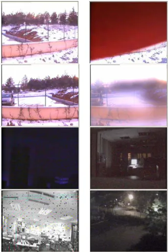
Figure 1: Several frames of test sequences. First row has normal
(left) and obscured camera image (right). Second row has normal (left) and reduced visibility image (right). The other two rows include frames from false alarm cases, showing low light cases in the third row and malfunction in the camera (left) and light changes caused by a flickering light source (right) in the fourth row.
6. System
A 16-input video processing system is designed [12] which feeds the compressed video data in motion wavelet format [13] to our system. The data compression chip described in [13] uses Daubechies’ 9/7 biorthogonal wavelets. Proposed algorithms are run on all 16 cameras in real-time. Detected incidences are recorded in system log with the detailed event type. Audible and visible alarms are also triggered on detection. An advanced option of the system is that, even the camera on which tampering was detected is not permanently recording, images prior to the event could be committed to the disk. This is achieved by a circular buffer of historical images kept in memory.
In real-life operation, due to differences in requirements and the environment, different levels of system sensitivity is required. This sensitivity can be incorporated with the thresholds used by the proposed algorithms. In order to determine these thresholds, system is run in normal conditions. For each threshold, related calculations are performed and thresholds are selected accordingly. Furthermore, user selected sensitivity is added to the system to control the thresholds in individual algorithms. This allows the user to fine-tune the system for specific needs.
7. Experimental results
In the experiments, the sensitivity setting is used as the default value of 50 (from a range of [1-100] where 100 is the most sensitive). In this setting, thresholds are calculated as follows:
Th1 = 1.4, Th2 = 1.4, Th3 = 0.75, Th4 = 0.5, Th5 = 0.5, Th6 = 0.1
Persistency check duration is set to 500 miliseconds. We have tested with several clips with various lengths for alarm and non-Alarm cases. Some of the frames from test sequences are shown in Figure 1.
For true alarm cases, a 4.5 minutes long sequence is used for OCV and a 2 minutes long sequence is used for RV. For false alarms, 6 hours of video is used with several false alarm conditions (low light, malfunction in camera, sudden light changes, slow light changes, camera shake) and several normal conditions (slow/fast/small/large objects passing through the scene). The results are summarized in Table 1 & 2. It should be noted that, changing the thresholds for increased sensitivity also results in increased false alarm rates and vice versa.
Table 1: True Alarm test results showing number of true alarms
as well as detection delay with and without false alarm checks. In the video sequences there are 20 true OCV alarms and 9 RV alarms respectively.
Without Any False Alarm Checks
With All False Alarm Checks Detected Alarms Delay per Alarm(sec) Detected Alarms Delay per Alarm(sec) OCV 20/20 16.2 20/20 19,2 RV 9/9 0.33 8/9 1.38
Table 2: The table compares the number of false alarm cases
when none of the false alarm checks are activated against when false alarm checks are activated one by one and when all checks are enabled.
Without
any check PC ECC LLC
With all checks
OCV 135/135 38/135 62/135 N/A 13/135
RV 158/158 68/158 120/158 147/158 36/158
As can be seen from these tables, adding checks to the system does not change the detected true alarm rate for OCV, where all the alarm conditions are detected correctly. Adding checks results in one missed true alarm case (out of nine alarms) for RV. In both cases it results in an increase in detection delay. Most of the delay is caused by the persistency check and can be controlled by the persistency check duration. While increasing the detection delay, these checks significantly reduce the number of false alarms as shown in Table 2. Considering the use cases of the system, such an increase to the detection delay is acceptable in favour of significantly reduced false alarm rate.
The test videos used have been designed to simulate extreme conditions including very low light conditions where the noise becomes dominant and camera malfunction as illustrated in Figure 1. In normal operating conditions, the false alarm rates are much lower as long as necessary precautions are taken to eliminate such cases (such as using infrared cameras at low light conditions or replacing malfunctioning cameras).
8. Conclusions
In this paper we introduced two methods, first one detects the obscured camera view and the second is used for detecting reduced visibility. It is also shown that the false alarm rates are reduced further by persistency and edge correspondence checks. A fail-safe condition for low-light conditions is also used. Experimental results confirm the detection performance.
References
[1] Aanderaa Instruments Mira Visibility Sensor 3544 , URL: http://www.aanderaa.com/render.asp?ID=141&closeBelow=141 &segment=46&session=
[2] C. Busch, E. Debes, “Wavelet transform for analyzing fog visibility”, IEEE Intelligent Systems and Their Applications, vol. 13, no. 6, pp. 66-71, Nov/Dec 1998.
[3] Vigilant Technologies, camera tampering detection, http://www.adyoron.com/site/item.php?ln=en&item_id=129&ma in_id=60
[4] 3VR Security, camera tamper, http://www.3vr.com/
[5] B.U. Töreyin, A.E. Çetin, A. Aksay, M.B. Akhan, “Moving Object Detection in Wavelet Compressed Video”, Signal Processing:Image Communication, EURASIP, vol. 20, pp. 255-26 (2005).
[6] M. Bagci, Y. Yardimci, A.E. Cetin, “Moving object detection using adaptive subband decomposition and fractional lower order statistics in video sequences”, Signal Process., pp. 1941– 1947, Dec. 2002.
[7] R.T. Collins, A.J. Lipton, T. Kanade, H. Fujiyoshi, D. Duggins, Y. Tsin, D. Tolliver, N. Enomoto, O. Hasegawa, P. Burt, L. Wixson, “A system for video surveillance and monitoring: VSAM final report”, Technical Report
CMURI-TR-00-12, Carnegie Mellon University, May 1998.
[8] G.L. Foresti, P. Mahonen, C.S. Regazzoni, Multimedia
Video-Based Surveillance Systems: Requirements, Issues and Solutions, Kluwer, Dordrecht, 2000.
[9] I. Haritaoglu, D. Harwood, L. Davis, “W4: who, when, where, what: a real time system for detecting and tracking people, in: Third Face and Gesture Recognition Conference”, pp.222–227., April 1998.
[10] J.C. Huang, W.S. Hsieh, “Wavelet-based moving object Segmentation”, Electron.Lett., 39 (19), Sept. 2003.
[11] A. E. Cetin and Rashid Ansari, “Signal recovery from wavelet transform maxima”, IEEE Trans. Image Processing, 1994
[12] Visioprime Ltd., 30 St. Johns Road, St. Johns, Woking, Surrey, GU21 7SA, URL: www.visioprime.com.
[13] Aware Inc., 40 Middlesex Turnpike, Bedford, Massachusetts, 01730, URL:www.aware.com, MotionWavelets real-time software video codec, 1999.