Towards Uniform Modeling and Holistic Testing of
Hardware and Software
Onur Kilincceker
University of Paderborn, Germany, and Mugla Sitki Kocman University, Turkey
Fevzi Belli
University of Paderborn, Germany, and Izmir Institute of Technology, Turkey
Abstract— This paper introduces an approach to uniform modeling and testing of hardware and software systems and their faults. As an example, for hardware under consideration, designs at a behavioral level will be used, implemented in Hardware Description Language (HDL). For software, an example will be borrowed from a graphical user interface design. Both examples will be modeled by finite state machines. The mutation of these models leads to lucid hardware and software fault models, respectively. Original models and their mutants will then be used to generate test cases for positive testing and negative testing, respectively, forming a holistic test strategy. A positive test is supposed to validate the system under legal (expected, regular) circumstances, whereas a negative test checks the behavior of the system under illegal (unexpected, irregular) situations. Non-trivial examples are used to validate and analyze the approach with respect to uniform modeling and testing capability.
Keywords—System/Fault Modeling, Finite State Machine, Validation, Holistic Testing, Mutation Testing
I. INTRODUCTION AND RELATED WORK
The automata-theoretic approaches are popular for modeling and testing of hardware systems back to the fifties of the last century [2], [3], [7]. For those systems, a finite state machine (FSM), or similarly, a finite state automaton (FSA), provides an abstract artifact to avoid unnecessary (irrelevant) features of the system under consideration (SUC). Thus, focusing on the relevant features of complex systems becomes easier. The development of integrated circuits usually starts with a specification provided by the customer. A designer then im-plements it in behavioral level in HDL (hardware description language) that is used for pre-silicon validation. After fixing errors, the developer converts it to an Register Transfer Level (RTL) design. The FSM model can be extracted from the HDL program that implements the sequential circuit under consideration.
Modeling software systems by FSA [1] started tentatively; nowadays FSA-centric models are popular, for example, state diagrams of UML [24]. Graphical user interfaces (GUIs) are good examples that can be modeled by FSA, be-cause they usually form strictly sequential processes and systems. FSA-based approaches to modeling GUI are event sequence graphs [9] and, slightly stylized, event flow graphs [23].
Holistic, model-based testing, proposed by Belli [9], [10] for software testing, introduces an integrated view encapsulating positive and negative testing. In positive testing, the system is validated against legal (correct, regular) inputs that are expected data generated from the original (supposedly fault-free) model, which is the conventional way of testing. In negative testing, the system is validated against illegal (faulty, irregular) inputs that are unexpected data generated from a faulty (mutant) model. Belli [9] also proposes FSA and regular expression, having
equivalent expressive power (forming type-3, regular languages) and test generation capability for modeling and testing graphical user interfaces. The holistic strategy is applied also to modeling and testing of web service composition [10], web application [11], interactive systems [12], hardware designs [5], and android applications [13].
Mutation testing, introduced by DeMillo et al. [13] and Hamlet [15], is a fault-based testing technique (Fig. 1). Mutants, that is, faulty versions, will be generated applying mutation operators to the SUC. Tests can then detect (kill) mutants. The effectiveness of a given test set can be determined by the mutation score, that is, the percentage of the killed mutants [16]. Recently, the idea has been extended to the model level, leading to model-based mutation testing [17], [18], [19].
This paper proposes FSM for modeling and testing both hardware and software in a uniform way. Fault models, namely mutants, and tests are generated using specifically defined mutation operators. Tests are carried out in a holistic way by positive and negative testing checking the SUC under expected and unexpected situations, respectively (Section II). Non-trivial examples, reaching a 100% fault coverage (Section III), illustrates the approach and are used to self-critically analyze its features (Section IV).
II. PROPOSED APPROACH
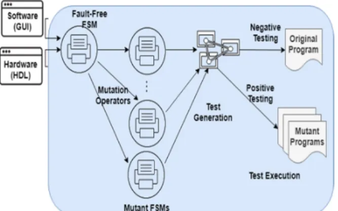
As an introduction to this section, Fig. 2 depicts the proposed approach that consists of three steps: (i) modeling by FSM, (ii) mutation to automatically construct fault models, and (iii) holistic testing using the test sequences generated from these models.
Software is a graphical user interface (GUI) that enables user and computer interaction by providing specific events in the proposed approach. An FSM model can automatically or manually generated from the GUI. Hardware is a Very Large Scale Integration (VLSI) design at behavioral level of abstraction. The design is implemented in Verilog Hardware Description Language (HDL) to specify any VLSI hardware. Proposed approach automatically generated an FSM model from the Verilog HDL of hardware. After obtaining the FSM model from either GUI or HDL, proposed approach generates mutant FSM models by Fig. 1: Mutation Testing
utilizing mutation operators. Then, the proposed approach generates test sequences from both original (fault-free) and mutant FSMs to utilize positive and negative testing shown in Fig. 2.
Fig. 2: Concept of the proposed approach
Finite State Machine (FSM) are used for modeling both correct and faulty behavior of the System Under Consideration (SUC).
Definition 1: Finite State Machine (FSM) [21] is represented by 5-tuples <S, Σ, δ, q0, F> where these are;
S: A finite set of states
Σ: A finite set of symbols (alphabet)
δ: A state transition function represented by a table; q0: An initial state is an element of Q
F: A finite set of final states is a subset of Q. A. Modeling SUT and Faults
The set of test sequences generated from fault-free FSM, forming a test suite, are run on mutant programs to realize positive testing. Test suites generated from mutant models are run on the fault-free program to realize negative testing. SUT is modeled by means of the FSM in a uniform way. Also, mutant FSM models represent behavioral fault in SUC. A behavioral fault affects input and output combination of SUC and may cause either failure or malfunction.
B. Mutation Operators
Following, mutation operators used in the approach (Table 1) will be defined.
TABLE 1: MUTATION OPERATORS
Operators Types
Insertion (I) Transition (T) State (S)
Omission (O) Transition
State
Replace (R) Transition
State
Definition 2: Transition Insertion (TI) inserts a transition into the FSM, that is, TI(si,e,sj)δ: δ → δ ∪ (s , e, s ), where the transition e∈ δ(Q) is inserted between states si , sj ∈ S, where δ, Q, and S are defined as in Definition 1.
Definition 3: State Insertion (SI) inserts a state into the FSM model, that is, SI(sk,e1, sl,e2 ,sm)δ: Q → Q ∪ (s ) and δ → δ ∪ {(s , 𝑒 , s ), (s , 𝑒 , s ), where the state sl is inserted between states sk and sm with transitions e1 and e2.
Definition 4: Transition Omission (TO) omits a transition from the FSM model, that is, TO(si,e,sj)δ: δ → δ ∖ (s , e, s ), where the transition e is omitted between states si and sj. Definition 5: State Omission (SO) inserts a state into the FSM model, that is, SO(sk,e1 sl,e2 ,sm)δ: Q → Q ∖ (s ) and δ → δ ∖ {(s , 𝑒 , s ), (s , 𝑒 , s ), where the state sl is omitted between states sk and sm with transitions e1 and e2.
Definition 6: Transition Replace (TR) replaces a transition from the FSM model, that is, TR(si,e,sj)δ: TO(si,e,sj)δ and TI(si,e,sj)δ, where the transition e is replaced between states si and sj.
Definition 7: State Replace (SR) replaces a state from the FSM model, that is, SR(sk, e1, sl,e2 ,sm)δ: SO(sk,e1 sl,e2 ,sm)δ and SI(sk,e1, sl,e2 ,sm)δ, where the state sl is replaced between states sk and sm with transitions e1 ande2.
C. Holistic Testing
The model (FSM) will be mutated by means of mutation op-erators. The original model and its mutants will then be used to generate test sequences, using a FSM-based test generation tool, for example, GraphWalker [4] that generates random test sequences from the given FSM model or PQ-RanTest [6] from equivalent regular expression model.
In positive and negative testing, the test sequences generated from fault-free and mutant models, and then are executed on fault-free and mutant programs, respectively. Thus, appropriate tests are run on the SUC with respect to corresponding models.
III. EXAMPLES AND EXPERIMENTS
A traffic light controller (TLC) and a commercial web service (ISELTA) are used to explain the approach and analyze its critical features. The hardware example, TLC, is represented in HDL at the behavioral level. An excerpt from the graphical user interface (GUI) of an Internet portal for touristic services forms the software example [7].
A. Example 1: Modeling Hardware And Their Faults The TLC used as an example has four traffic signals for four pathways (Fig. 3). Every pathway is provided with lights Red, Yellow, and Green. The TLC, implemented in Verilog HDL, is operated on Xilinx Basys 3 Artix-7 FPGA develop-ment board using the Vivado 2017.4 design suite [20].
Fig. 3: Block view of TLC
Fig. 4 represents a fraction of the HDL Verilog code for the TLC hardware.
The HDL code declares the main module of the controller, called “Lights”, in line three, including the main variables. The “always” block defines procedures of this main module and is triggered by a clock signal. The “begin” block executes the “case” statement depending on the “state”
variable that defines current, next state of the hardware and corresponding status of outputs, called “output light status” in line 14 for the state “0000”. There are nine states in the HDL code and 16 transitions as depicted in Fig. 5.
1 2 3 4 5 6 7 8 9 10 11 12 13 14 15 16 17 18 19 20 21 22 23 24 25 26 27 `timescale 1ns / 1ps ...
module Lights (n_lights,s_lights,e_lights,w_lights,clk,btn); ...
always @( clk_point1hz ) begin
case (state) 4'b0000: begin
$display ("The value of input: %h, state %d", input_light_status,state) ; segment = 7'b0000001; if (btn==0) begin state = 4'b1000; output_ligth_status = 16'h1444; n_lights = 3'b001; s_lights = 3'b100; e_lights = 3'b100; w_lights = 3'b100; end …. 4'b0111: ... 4'b1000: ...
endcase // case (state) end
endmodule
Fig. 4: A fraction of the HDL code for TLC 1) Modeling TLC
The FSM model in Fig. 5 is extracted from the HDL code of TLC using JFLAP as a tool [22]. Table 2 depicts the be-havior of TLC; the input/output combinations are encoded and identified by symbols. The FSM model for TLC has nine states and 18 transitions.
Fig. 5: FSM of the original (fault-free assumed) TLC
In Table 2, the symbol “g” stands for the light “green” , “y” for “yellow”, and “r” for “red” that are coded in the circuit by “001”, “010”, and “100” in binary format, respectively.
TABLE 2. ENCODING OF TRANSITIONS
Sym* Com** Sym* Com** Sym* Com**
a grrr 0 / yrrr g rrrg 0 / rrry n xxxx b - rrgr 0 / rrrr b yrrr 0 / rgrr i rrry 0 / grrr o xxxx b - rryr
0 / rrrr c rgrr 0 / ryrr j xxxx b - grrr 0 / rrrr p xxxx b - rrrg 0 / rrrr d ryrr 0 / rrgr k xxxx b - yrrr 0 / rrrr r xxxx b - rrry 0 / rrrr e rrgr 0 / rryr l xxxx b - rgrr 0 / rrrr s xxxx 1 / rrrr f rryr 0 / rrrg m xxxx b - ryrr 0 / rrrr h xxxx 0 / grrr *Sym: Symbol, **Com: Combination
2) Fault Modeling through Mutation
Exemplary, three mutants are constructed using the mutation operators (Table 1) in Section II.B (Definition 2 through 7). These mutants embody typical faults and will be used for test generation (Section III.C).
Fig. 6: Mutant one of TLC
The first mutant (Fig. 6) models the fault that occurs as a combination of the omission of a state and the insertion of transition (Table 3). This fault depicts a sequence of events, that is, the symbol “c” correctly occurs after the symbol “b”. However, the symbol “d” follows the symbol “b” in the cor-rupted sequence. So, the correct sequence is “bcd”, the faulty one is “bde”.
TABLE 3: MUTATION OPERATORS TO CONSTRUCT MUTANT ONE OF TLC
Order Operators
1 SO(s2,c, s3,d,s4)δ: Q → Q ∖ (s ) and δ → δ ∖ {(s , 𝑐, s ), (s , 𝑑, s )
2 TI(s2, d , s3)δ: δ → δ ∪ (s , d, s ).
The second mutant, shown in Fig. 7, models the fault that occurs as a combination of omission and insertion of transi-tions. This mutant represents a corruption in the input/output sequence. The inserted transitions are u, v, and y that repre-sent “ryrr 0/rrgg”, “rrgg 0/ rrgr”, and “xxxxx – rrgg 0/ rrrr”, respectively.
Fig. 7: Mutant two of TLC
Table 4 lists the mutation operators to acquire Mutant two: one state omission and three transition insertions operators, applied consecutively to the original model.
TABLE 4: MUTATION OPERATORS TO CONSTRUCT MUTANT TWO OF TLC
Order Operators
1 TO(s3, d, s4)δ: δ → δ ∖(s3, d, s4). 2 SI(s3,u, s9, v ,s9)δ: Q → Q ∪ (s ) and δ → δ
∪ {(s , u, s ), (s , v , s ) 3 TI(s9, y ,s0)δ: δ → δ ∪ (s , y, s ).
B. Example 2: Modeling Software And Their Faults ISELTA (Isik’s System for Enterprise Level Web-Centric Tourist Applications) is a commercial Internet portal for hotel providers to market tourist services, for example online reservations. It is a cooperative work between a travel agency (ISIK Touristic) and University of Paderborn, implemented in PHP. Following, the “Specials” module of the ISELTA is used as an example that enables providers to market their specific and periodical offers (Fig. 8).
Fig. 8: The opening window of “Special” module for ISELTA 1) Modeling ISELTA
The FSM in Fig. 9 models the GUI of “Specials” module, constructed using the graph designer JFLAP [22] as already used for the FSM of TLC (see Section 2).
Fig. 9: Original (fault-free) FSM of “Specials”
Table 4 lists the letters that symbolize actions of the user, for example, for filling an input box, clicking a button, or removing a text from an input box.
TABLE 4. GUI ACTIVITIES ON THE GUI OF “SPECIALS”
Symbol Action Symbol Action
k Click edit z Set description text
l Click save r Remove all text
v Click Add t Remove title input
u Set title text p Remove price input x Set number value n Remove number input y Set price value
2) Fault Modeling through Mutation
Again, the mutation operators defined in Section 2 will be used to generate typical faults as mutants of “Specials”. TABLE 5: MUTATION OPERATORS TO CONSTRUCT MUTANT ONE OF “SPECIALS” Order Operators 1 TO(s0, u ,s9)δ: δ → δ ∖ (s , u, s ) 2 TO(s3, u ,s4)δ: δ → δ ∖ (s , u, s ) 3 TI(s8, z ,s4)δ: δ → δ ∪ (s , z, s ). 4 TI(s2, z ,s4)δ: δ → δ ∪ (s , z , s ).
Fig. 10 shows a mutant of the original FSM. The tester needs to consecutively apply the mutation operators given in TABLE 5 to acquire mutant one.
Fig. 10: Mutant one of “Specials”
Fig. 11 illustrates the Mutant two of the original FSM, which will be constructed by consecutively applying the mutation operators given in TABLE 6.
TABLE 6: MUTATION OPERATORS TO CONSTRUCT MUTANT TWO OF “SPECIALS”
Order Operators
1 TR(s0, k, s6)δ: TO(s0, k, s6)δ and TI(s0, k, s5)δ. 2 TR(s5, k, s6)δ: TO(s5, k, s6)δ and TI(s5, k, s5)δ.
Fig. 11: Mutant two of “Specials”
C. Test Generation From Models and Testing
Holistic testing requires the generation of test sequences from both fault-free model and its mutants for positive and negative testing, respectively. Graphwalker [4] offers options also for test generation and coverage criteria selection. Exemplary, random test generation option and edges (transition) coverage criterion is chosen. The edge coverage criterion is set to %85 to avoid excessive run times of the tool.
1) Test Generation TLC
For the fault-free model of TLC (Section III.A.1), Graphwalker [4] generates a test suite, a subset of which is listed in TABLE 7. These test sequences will be executed on mutants of the HDL program (Fig. 4) for positive testing. TABLE 7: A TEST SUITE FOR TLC (SEE TABLE 2 FOR SYMBOLS OF THE TEST SEQUENCES) Test Sequence 1 hablss 2 habcdeo 3 habcdefgiabcdefgijss 4 habcdnsss 5 habcdefgiabcmss
Similarly, a set of test sequences are generated from the three mutant models and executed on a fault-free HDL program for negative testing.
2) Test Generation ISELTA
Graphwalker will be used also for positive and negative test-ing of “Specials” module of ISELTA (TABLE 8 ).
TABLE 8: A TEST SUITE FOR “SPECIALS” OF ISELTA Test Sequence 1 kxlkzuyxl 2 yxzuv 3 yxzuvklkuyl 4 yxzuv 5 xyzuvkzuyl
D. Tests and Results
In positive testing of the examples, sets of test sequences generated from the original model of TLC and ISELTA execute on mutant HDL and GUI programs, respectively. In positive and negative testing, the test sequences generated from fault-free and mutant models are executed on fault-free and mutant programs, respectively. To validate the actual programs of TLC and ISELTA with respect to corresponding models, test sequences generated from these models are executed on TLC and ISELTA. In negative testing, the sets of test sequences generated from three mutant models of TLC and ISELTA execute on fault-free HDL and GUI programs. TABLE 9 shows the results collected from the experiments for positive and negative testing. Test sequences executes automatically on ISELTA using Selenium [29] test automation environment and on TLC using Xilinx Vivado [30] by means of simulation. E. Discussion of the Results
Although only 85% transition coverage was selected, the fault coverage is 100% for both positive and negative testing of TLC and ISELTA for three mutants that model specific faults. A fault is detected if any test sequence generated from the corresponding model fails while running the corresponding program. The length of test suites defines the number of symbols contained in the set of test sequences. This length is 1354 for the original model of TLC, as random tests usually generate a great number of test sequences. The length results depend also on the structure of the model. For example, the length of the original model of the “Specials” module of ISELTA is just 99 because a less complex of model of ISELTA is chosen than the model of
the TLC. This fact affects the results of the test suite length of mutant models.
TABLE 9: RESULTS OF POSITIVE AND NEGATIVE TESTING OF THE EXAMPLES
TLC ISELTA PT NT PT NT Fault Coverage 100 100 100 100 Length of Test Suite (number of symbols) 1354 813* 99 66* Test Generation Time (seconds) 15 16* 14 15*
*Average of three mutants, PT: Positive Testing, NT: Negative Testing. TABLE 9 shows the average results for the length of test suites and test generation time for negative testing. However, surprisingly, the test generation time for both TLC and ISELTA are close to each other, about 15 seconds in positive and negative testing. Despite this closeness of the test execution times (both about 15 seconds), the length of the test suite of TLC is almost 10 times greater than the length of the test suite of “Specials” module of ISELTA. A drawback of testing experiment is selection small set to calculate metrics given in TABLE 9. However, the results provide preliminary observation of usefulness of the approach proposed. To calculate more realistic metrics, we plan to generate random mutants with proper amount to evaluate effectiveness and generality of the approach. F. Threats to the Validity
Current work proposes a uniform modeling hardware and software systems including their faults. This uniform model is supposed to be a deterministic FSM. The faults are then represented by mutants of this FSM obtained by mutation operators. However, an operator, or a combination of operators, may lead to a nondeterminism, allowing more than one option for transferring a state to another one. This would lead to a threat to internal and external validity. The examples used in this paper do not contain nondeterminisms. This cause, however, no limitation of the approach, because for any nondeterministic FSM an equivalent, deterministic one can be constructed [21]. Further, the original model will be supposed to be fault-free. This assumption is of crucial importance, not only for the approach introduced in this paper, but for any fault-oriented validation method, because the model of the SUT will be used as a reference for generating test cases (oracle problem, [25]). Several techniques have been suggested for ensuring the correctness of the model, for example model checking [26].
Finally, the used mutants provide model-based mutation ex-amples carried on model domain. However, the mutants lead special types of fault models which also can be utilized by based mutation. The reader may refer to [7] for code-based mutants of ISELTA. Moreover, the current paper utilizes mutation testing for generation of fault specific models and programs instead of qualification of test suites as it is in conventional usage.
IV. RESULTS AND CONCLUSION
This paper proposes a uniform modeling approach to hard-ware and softhard-ware systems under consideration (SUC). Finite state machines (FSM) are exemplary used for
modeling both integrated circuits, implemented in HDL, and for modeling graphical user interfaces (GUI), implemented in PHP. Faults are modeled by mutants using novel, formally defined mutation operators.
Two non-trivial, real-life examples illustrate the approach, and enable tool-supported experiments to analyze its critical features, such as performance of the test generation and test execution times, fault detection capability. Although a rela-tively low coverage criterion is chosen, a 100% fault detec-tion could be achieved.
The domains of the selected fault models for hardware and software are mapped into the code domain by using code-based mutation operators. However, the codes of the mutants corresponding to the model-domain faults of the software example are publicly available [7].
Future work is planned to extend the formal foundation of the approach by considering more powerful modeling tech-niques, for example by advanced (colored) Petri nets and pushdown automata. This theoretic work is to immediately be accompanied by empirical validation. Moreover, it is possible to encounter problem of state explosion if the program or model becomes very complex and large. To cope with this problem, in our future work, we plan to use the techniques for model refinement [26] and/or model decomposition [28] to increase the scalability of the proposed approach.
REFERENCES
[1] T. S. Chow, (1978), Testing software design modeled by finite-state machines. IEEE transactions on software engineering, (3), 178-187. [2] A. Gill. "State-identification experiments in finite automata."
Information and control 4.2-3 (1961): 132-154.
[3] G. H. Mealy, (1955), A method for synthesizing sequential circuits. The Bell System Technical Journal, 34(5), 1045-1079.
[4] GrapWalker tool, Available Online: http://graphwalker.github.io/, Last accessed August 2019.
[5] O. Kilincceker, E. Turk, M. Challenger, and F. Belli. "Applying the Ideal Testing Framework to HDL Programs." In ARCS Workshop 2018; 31th International Conference on Architecture of Computing Systems, pp. 1-6. VDE, 2018.
[6] O. Kilincceker, E. Turk, M. Challenger, and F. Belli. "Regular Expression Based Test Sequence Generation for HDL Program Validation," 2018 IEEE International Conference on Software Quality, Reliability and Security Companion (QRS-C), Lisbon, 2018, pp. 585-592.
[7] T. Mott, (1969). E. J. McCluskey. Introduction to the theory of switching circuits. McGraw-Hill Book Company, New York, St. Louis, San Francisco, Toronto, London, and Sydney, 1965, xv 318 pp. Journal of Symbolic Logic, 33(4), 631-631. doi:10.2307/2271427 [8] Mutants of ISELTA, Available Online: http://iseltamutants.ivknet.de/,
Last accessed August 2019.
[9] F. Belli, Finite state testing and analysis of graphical user interfaces. Software Reliability Engineering, 2001. ISSRE 2001. Proceedings. 12th International Symposium on. IEEE, (2001).
[10] F. Belli, A. T. Endo, M. Linschulte & A. Simao, (2014). A holistic approach to model‐based testing of Web service compositions. Software: Practice and Experience, 44(2), 201-234.
[11] F. Belli & M. Linschulte (2008). On negative tests of web ap-plications. Annals of Mathematics, Computing & Teleinformatics, 1(5), 44-56
[12] F. Belli, C.J. Budnik, and A. Hollmann. "Holistic Testing of Interactive Systems Using Statecharts." Sicherheit. 2006.
[13] G. Mercan, E. Akgündüz, O. Kilincceker, M. Challenger, and F. Belli, (2018, September 10-12). Android uygulaması testi için ideal test ön çalışması. A. Tarhan and Murat E. (Eds.), Paper presented at 12th Turkish National Software Engineering Symposium, UYMS 2018; Istanbul; Turkey.
[14] R. A. DeMillo, J. L. Richard, and F. G. Sayward. "Hints on test data selection: Help for the practicing programmer." Computer 11.4 (1978): 34-41.
[15] R.G. Hamlet, "Testing Programs with the Aid of a Compiler", IEEE Trans. Software Eng., vol. 3, no. 4, pp. 279-290, July 1977. [16] Y‐S. Ma, J. Offutt, and Y. R. Kwon. "MuJava: an automated class
mutation system." Software Testing, Verification and Reliability 15.2 (2005): 97-133.
[17] S. C. P. F. Fabbri, , J. C. Maldonado, and M. E. Delamaro. "Proteum/FSM: a tool to support finite state machine validation based on mutation testing." Proceedings. SCCC'99 XIX International Conference of the Chilean Computer Science Society. IEEE, 1999. [18] F. Belli, C. J. Budnik, A. Hollmann, T. Tuglular, & W. E. Wong,
(2016). Model-based mutation testing—approach and case studies. Science of Computer Programming, 120, 25-48.
[19] B. K. Aichernig, H. Brandl, E. Jöbstl, W. Krenn, R. Schlick, & S. Tiran, (2015). Killing strategies for model‐based mutation testing. Software Testing, Verification and Reliability, 25(8), 716-748. [20] Xilinx Vivado, Available online:
https://www.xil-inx.com/products/design-tools/vivado.html, Last accessed August 2019.
[21] J.E. Hopcroft, R. Motwani, and J.D. Ullman. Introduction to Automata Theory, Languages, and Computation. Harlow, Essex: Pearson Education, 2014.
[22] S. Rodger, T. Finley, JFLAP - An Interactive Formal Languages and Automata Package, ISBN 0763738344, Jones and Bartlett (2006). [23] A. M. Memon, "An event‐flow model of GUI‐based applications for
testing." Software testing, verification and reliability 17.3 (2007): 137-157.
[24] Y. D. Salman, and N. L. Hashim. "Automatic test case generation from UML state chart diagram: a survey." Advanced Computer and Communication Engineering Technology. Springer, Cham, 2016. 123-134.
[25] E. T. Barr, M. Harman, P. McMinn, M. Shahbaz, & S. Yoo, (2014). The oracle problem in software testing: A survey. IEEE transactions on software engineering, 41(5), 507-525.
[26] E. M. Clarke, Jr., O. Grumberg, and D. A. Peled. 2000. Model Checking. MIT Press, Cambridge, MA, USA.
[27] F. Belli, N. Güler, and M. Linschulte: Layer-centric testing. FERS-Mitteilungen: vol. 30, no. 1 (2012).
[28] S. Devadze, E. Fomina, M. Kruus, and A. Sudnitson,: Web-based system for sequential machines decomposition. In: EUROCON 2003, The IEEE Region 8, vol. 1, pp. 57-61 (2003).
[29] Selenium Test Automation Environment, Available Online: https://www.seleniumhq.org/ , Last accessed August 2019.
[30] Xilinx Vivado, Available online:
https://www.xilinx.com/products/design-tools/vivado.html, Last accessed August 2019.