• Sonuç bulunamadı

Bearing capacity and bulging behavior of Geogrid encased stone columns

N/A
N/A
Protected

Academic year: 2021

Share "Bearing capacity and bulging behavior of Geogrid encased stone columns"

Copied!
14
0
0

Yükleniyor.... (view fulltext now)

Tam metin

(1)

BEARING CAPACITY and BULGING BEHAVIOR of GEOGRID ENCASED STONE COLUMNS

1Ahmet DEMİR; 2Talha SARICI

1Department of Civil Engineering, Osmaniye Korkut Ata University, Osmaniye, Turkey, 2Department of Civil Engineering, Inonu University, Malatya, Turkey,

1ahmetdemir@osmaniye.edu.tr, 2talha.sarici@inonu.edu.tr

(Geliş/Received: 16.02.2016; Kabul/Accepted in Revised Form: 29.03.2016)

Abstract: In recent years, geogrid encasement has been used to extend the utilization of stone columns to improve soft soil’s properties. This paper investigates the influence of geogrid encasement on the performance of stone columns in soft clay deposits. Experimental and numerical studies were conducted to figure out behavior of stone columns with and without geogrid reinforcement. The small scale laboratory tests were carried out. In addition, PLAXIS which is a finite element package intended for the two dimensional analysis of deformation and stability in geotechnical engineering was used to numerical studies. Before conducting the numerical studies, the validation between results of the experimental studies and numerical analysis was performed. After validation, the numerical studies were performed with different parameters such as the rigidity effect of geogrid, depth of geogrid reinforcement and lateral bulging of the stone columns. In addition, group of stone column was investigated. As a result of this studies, load carrying capacity and bulging behavior of the geogrid encased stone column was significantly influenced from the depth and the stiffness of the geogrid.

Keywords: Bulging, Finite Element, Geogrid Encasement, Soft Clay, Soil Stabilization, Stone Column

Geogrid Kaplı Taş Kolonların Taşıma Kapasitesi ve Genişleme Davranışı

Öz: Son yıllarda yumuşak zeminlerin iyileştirilmesi için kullanılan taş kolonun kullanımını artırmak için geogrid kaplama kullanılmaktadır. Bu çalışmada, geogrid kaplamanın, yumuşak zemin yatağı içerisindeki taş kolonun performansına olan etkisi araştırılmıştır. Geogrid kaplı ve geogridsiz taş kolonun davranışını belirlemek için deneysel ve numerik çalışmalar gerçekleştirilmiştir. Deneysel çalışma için küçük ölçekli laboratuvar testleri gerçekleştirilmiştir. Ayrıca, geoteknik mühendisliğinde iki boyutlu deformasyon ve stabilite analizleri için tasarlanmış sonlu elemanlar programı olan PLAXIS numerik çalışmalar için kullanılmıştır. Numerik çalışmalar gerçekleştirilmeden önce deneysel çalışmaların ve numerik analizlerin uyumluluğu kontrol edilmiştir. Uyum elde edildikten sonra taş kolonda geogridin rijitliğinin, geogrid kaplama boyunun ve yanal genişleme gibi farklı parametrelerin etkisi numerik çalışmalar ile araştırılmıştır. Ek olarak grup kolonlar da incelenmiştir. Bu çalışmanın sonuncu olarak, geogridin kaplama boyu ve rijitliği geogrid kaplı taş kolonun yük taşıma kapasitesini ve genişleme davranışını önemli ölçüde etkilemektedir.

Anahtar Kelimeler: Genişleme, Sonlu Elemanlar Analizi, Geogrid Kaplama, Yumuşak Kil, Zemin İyileştirme,

Taş Kolon

(2)

INTRODUCTION

Every geotechnical engineer know that engineering properties of weak soil should be improved. Therefore, a lot of soil improvement method has been developed. Stone column method is one of the considerable method of soil improvement and it has been used widely over the last 30 years in many countries around the world as a ground improvement method (Black et al. 2007). A stone column is theoretically an upright cylinder that contains compacted granular material such as crushed stone. Soil stabilization by the stone column method overcomes the settlement problem and low stability. Another advantage of stone column method is the simplicity of its construction (Isaac and Girish 2009). The undrained shear strength of the surrounding soil of stone column is generally important factor for the strength of stone columns. The range of 5-15 kPa shear strength for the surrounding soil of stone column is suggested as a minimum value (Wehr 2006). Below this range of shear strength, the lateral confinement provided by surrounding natural soil may not be sufficient to prevent column failure. For this reason, some methods have been developed to reinforcement stone column. Encasement of the stone column with geosynthetics is one of the stone column reinforcement method and has been successfully used to extend the use of stone columns to extremely soft soils. Geosynthetic encased stone columns is stiffer, stronger and more resistant to dispersion than ordinary stone column. There are different studies to understand stone column behavior in the literature. These are field, laboratory, numerical and theoretical studies. Watts et al. (2000) and Engelhardt and Golding (1975) conducted full scale field tests. Priebe (1995) suggested to estimate settlement based on unit cell concept for stone columns. Unit cell concept is also used by Barksdale and Bachus (1983). In this concept, the area of the stone column pattern represented by a single column, depending on column spacing and this area is considered for the analysis. In addition it is supposed that lateral deformation in soil at the boundary of unit cell is zero. This concept has been useful to researchers because experimental studies have been quicker and becomes meaningful. Ambily and Gandhi (2007) conducted an experimental study on single column and group columns. Katti et al. (1993) suggested a method for geosynthetic encased stone column. Ayadat and Hanna (2005) worked on encased the stone column. Bauer and Al-Joulani (1996) conducted some tests to found out effect of encasement. Balaam et al. (1978) suggested a finite-element approach. Malarvizhi and Ilamparuthi (2008) conducted triaxial testing on encased stone columns and analyses numerically. Andreou et al. (2008) carried out a series of laboratory tests. Keykhosropur et al. (2012) conducted to understand performance of geosynthetic-encased columns using ABAQUS software. Kempfert (2003) was used a injecting a binder into the column for reinforcement. It is clear from the literature that stone column method is improves the soil condition but it is limited to surrounding natural soil. Therefore, nowadays, researchers mainly focused on the behavior of the reinforced stone column.

In this study, the influence of geogrid encasement on the performance of stone columns in soft clay deposits was evaluated. Firstly, experimental studies and then numerical analyses were conducted. Numerical analyses were carried out using two-dimensional Plaxis software. Before conducting the numerical analysis, the validity of the numerical model was checked using laboratory model tests. After the good agreement between numerical and experimental studies, the numerical analyses were carried out with different parameters such as the effect of geogrid stiffness, depth of geogrid encasement and lateral bulging of the stone columns. In addition, group of stone column was studied.

MATERIAL and METHODS Experimental Work

In this paper, the behavior of circular footing rested on natural clay deposits stabilized with stone columns with and without geogrid reinforcement was investigated using small scale laboratory tests. Finite-element (FE) analyses have also been performed using with the commercially available software

(3)

package PLAXIS. Before conducting the analysis, the validity of the constitutive model was proved using laboratory tests.

Materials Used

Clay, crushed stone, and geogrid were used for current experimental study. Clay was taken in the field and then dried. The initial water content of clay was 6%. Dry clay was powdered to passing through 2 mm sieve for easy processing and uniform water content. Afterwards, clay was mixed with required water content. A series of unconfined compressive strength (UCS) tests were carried out on cylindrical specimen with 38 mm diameter and 76 mm height to determine the moisture content corresponding to 15 kPa undrained shear strength of the clay. UCS tests were conducted on clay samples at different water content. UCS values (undrained shear strength, cu) of the clay with water content is shown in the Figure 1.

Figure 1. Variation of undrained shear strength with water content (Sarıcı et al. 2013)

All the laboratory experiments were performed with stone columns surrounded by clay. Based on the Figure 1., water content of the clay was 35% and this amount was kept as the same in all tests. A series of laboratory tests were conducted for determine properties of clay. The properties of clay is shown in the Table 1.

Table 1. Properties of clay (Sarıcı et al. 2013)

Parameters Units Values

Specific gravity (kN/m3) 26 Liquid limit (%) 55 Plastic limit (%) 22 Classification - CH Water Content (%) 35 Unit weight (kN/m3) 18 Undrained cohesion (kPa) 15

The stone columns were formed from crushed stones, which was classified GP. Crushed stones (aggregates) of sizes between 10 and 2 mm were used to form stone column. The particle size distribution for stone column and clay materials are indicated in Figure 2. The maximum dry unit weight (kmax) and minimum dry unit weight (kmin) of the aggregate are 16.9 and 15.2 kN/m3, respectively. Other properties of the aggregate for the stone column are given in Table 2.

0 20 40 60 80 100 0 20 40 60 cu ( k P a) ω (%)

(4)

Figure 2. Particle size distribution for stone column and clay materials Table 2. Properties of crushed stones

Parameters Units Values

Specific gravity (kN/m3) 28.5

Density (kN/m3) 16.3

Maximum dry unit weight (kN/m3) 16.9 Minimum dry unit weight (kN/m3) 15.2 Internal friction angle (degree) 440

Geogrid was used for encasement of the stone column. Stone column was restrained by the geogrid encasement. In such situation, geogrid encasement provided additional confinement for improved stone column performance. Geogrid used in the experimental study, is commercially available from GEOPLAS Company. The properties of geogrid taken from GEOPLAS Company are shown in the Table 3.

Table 3. Properties of geogrid

Parameters Units Values

Type of Material - Polypropylene

Weight per Unit Area (g/m2) 200

Max. Tensile Strength, md/cmd (kN/m)  30 / 30

Tensile Strength of 2% Elongation, md/cmd (kN/m) 12 / 12 Tensile Strength of 5% Elongation, md/cmd (kN/m) 24/ 24

Aperture (mm x mm) 40  40

Tests Procedure

All tests have been carried out in a clay bed prepared at water content of %35. The clay was mixed with additional required water. All clay samples were kept in waterproof bag during about a week for uniform water content. To prepare the clay bed, a circular tank of 60 cm diameter and 60 cm high was used in all the tests. Before filling the tank with clay, inner surface of tank wall was greased to prevent friction between clay and tank wall. Clay was filled in the tank in layers with measured quantity by weight and was filled at equal layers of 50 mm thickness. Each layers was compacted with steel hammer. In all the tests, all clay bed height was taken as 25 cm and same procedure was performed to prepare the clay bed. A steel pipe with 5 cm diameter was used for preparing the stone column. The stone column was built from beginning to end of the clay bed surface. Pipe was located at the center of the tank. Crushed stone was filled into the pipe with total weight of crushed stone was divided into equal batches

0 20 40 60 80 100 0,001 0,01 0,1 1 10 100 P er ce n ta ge F in er Particle Size (mm) Soft Clay Stone Column

(5)

to fill up the hole. The crushed stones were compacted to a density of 16.30 kN/m3 to construct stone column Outer surface of pipe wall was greased to prevent friction between clay and pipe wall. For geogrid encasement, geogrid was formed a cylindrical shape which is the same dimensions as the stone column. Steel circular plate of 5cm diameter and 25 mm thickness was used as a foundation to apply the load. Two LVDTs were attached for measuring the settlement of the footing during the application of load. The sketch of test setup is shown in the Figure 3. In experimental study, the behavior of circular footing rested on unreinforced clay deposits, clay deposits stabilized with stone columns and clay deposits stabilized with geogrid encasement stone columns was investigated using small scale laboratory tests. Summary of experimental study is shown in the Table 4.

Figure 3. Schematic test setup Table 4. Summary of experimental study Test

Series Test Description

Diameter of The Footing

Diameter of The Stone Column I Loading on Unreinforced Clay Bed 50 mm -

II Loading on Stone Column Reinforced Clay

Bed 50 mm 50 mm

III Loading on Geogrid Encased Stone Column

Reinforced Clay Bed 50 mm 50 mm

Numerical Analyses

The finite element method is used widely in many civil engineering problems. Capabilities of finite element method make it possible to simulating the construction method and to investigate the behavior of shallow footings and surrounding soil throughout the construction process, not just at the limit

(6)

equilibrium conditions. (Laman and Yıldız 2009). Numerical analyses were carried out by using the Plaxis 2D software. It works based on a finite element method and specially developed for the analysis of geotechnical engineering problems (Brinkgreve 2004). Finite element model was simulated using 15-node triangular elements. Because of the symmetry of the test tank used in experimental study, axisymmetric modelling is considered in the numerical analyses. Finite element model in Plaxis is shown in Figure 4. An elastic-plastic Mohr Coulomb (MC) model was chosen to simulate clay soil and stone column behavior. Table 5 shows a clay soil and crushed stone parameters used in numerical analyses. Several limitations that should be mentioned. The models created in this research were based on data obtained from present tests. The further testing and verification is recommended for the use of these models in other soils or with significantly larger plate diameters. (Demir and Ok, 2015)

Figure 4. Finite element model in Plaxis Table 5. Soil properties used in numerical analyses

Parameter Units Clay

Value Stone Column Value Unit weight, (kN/m3) 18 21 Loading stiffness, Eu (kN/m2) 290 65000 Cohesion, c (kN/m2 ) 15 1 Poisson’s ratio, v - 0.35 0.3

Friction angle, (degrees) 1 45

Dilatancy angle, ( - 30O) (degrees) 0 15

RESULTS and DISCUSSION

Verification of Numerical Analyses by Experimental Results Test Series I: Unreinforced Clay Bed

In test Series I, laboratory test and numerical analyses were conducted using circular foundation rested on an unreinforced clay bed. Load-settlement curves of both of laboratory test and numerical analyses are presented in Figure 5. The horizontal and vertical axes show the settlement ratios and the

(7)

bearing capacities, respectively. The settlement ratio (s/D) is defined as the ratio of the footing settlement (s) to the footing diameter (D), expressed as a percentage. It is clear from the figure that the results obtained by the numerical analysis are in good agreement with the experimental results. It is clear from the Figure 5.that the settlement pattern generally resembles a typical local shear failure.

Figure 5. Curves of bearing capacity against settlement for Series I Test Series II: Stone Column Reinforced Soft Clay Bed

In test Series II, laboratory test and numerical analyses were conducted using circular foundation rested on a stone column reinforced clay bed. Figure 6 shows the relation of bearing capacity to settlement ratio obtained from the numerical analyses and experimental studies of Series II. As seen from the figure, the results obtained by the numerical analysis are in good agreement with the experimental results. It is observed that the load-settlement curve is rounded and becomes steeper and takes on an almost a linear shape. A peak load is never observed and no definite failure point can be established. The mode of failure can be described as a local shear failure.

Figure 6. Curves of bearing capacity against settlement for Series II Test Series III: Geogrid Encased Stone Column Reinforced Soft Clay Bed

In test Series III, laboratory test and numerical analyses were conducted using circular foundation rested on a geogrid encased stone column reinforced clay bed. Both of numerical and experimental results are shown in Figure 7. It is clear from the figure that results obtained by the numerical analysis are in good agreement with the experimental results.

0 30 60 90 120 0 10 20 30 40 q ( k P a) s/D (%) Test FEM 0 100 200 300 400 500 0 10 20 30 40 q ( k P a) s/D(%) Test FEM

(8)

Figure 7. Curves of bearing capacity against settlement for Series III Comparison of Test Series

The results derived from the numerical analyses for Test Series I, Test Series II and Test Series III are shown together in Figure 8. As seen from the figure that stone column increases the bearing capacity of unreinforced clay bed and geogrid encasement improves the performance of stone column. At the constant values of s/D (%), the improvement in bearing capacity is about %256 between test series I and II for stone column reinforcement. On the other hand the improvement is approximately %72 between test series II and III for geogrid encasement.

Figure 8. The comparison of numerical analyses for different test series The Effect of Geogrid Stiffness

After achieving well agreement between the numerical analyses and experimental studies, the numerical analyses were continued. Geogrid stiffness was examined by changing the geogrid stiffness values. As shown in the Figure 9, while geogrid stiffness increases, bearing capacity of the stone column increases. 0 150 300 450 600 750 0 7 14 21 28 35 q (kP a) s/D(%) Test FEM 0 150 300 450 600 750 0 10 20 30 40 q ( k P a) s/D (%) Series III Series II Series I

(9)

Figure 9. Geogrid stiffness effect on the column encasement The Effect of Geogrid Encasement Depth

Geogrid encasement depth was also investigated in this study. There are three different L/H ratio was selected for study. L is the geogrid encasement depth from the top portion of stone column. H is the stone column depth which is 25 cm in all numerical analyses. Geogrid stiffness kept constant which is the 10 kN/m while L/H ratio is variable. As seen from the Figure 10 that load carrying capacity decreases by the decrease of the geogrid encasement depth.

Figure 10. Effect of geogrid encasement depth Lateral Bulging

The lateral bulging was measured along the depth of the stone column when footing had a 25 mm settlement. The lateral bulging observed along the depth of the only stone column and stone column encased with geogrid of different stiffness values is shown in Figure 11. It is clear that geogrid encasement reduces maximum lateral bulging and maximum lateral bulging decreases with the increases in stiffness of geogrid.

0 800 1600 2400 3200 4000 0 10 20 30 40 50 q ( k P a) s/D (%) EA=160 kN/m EA=80 kN/m EA=40 kN/m EA=20 kN/m EA=10 kN/m 0 200 400 600 800 1000 0 10 20 30 40 50 q ( k P a) s/D (%) L/H=1 L/H=0,5 L/H=0,25

(10)

Figure 11. Lateral bulging along the height of the stone column for different geogrid stiffness The lateral bulging observed along the height of the only stone column and stone column encased with geogrid of different L/H ratio is shown in Figure 12 and Figure 13. It is clear that maximum lateral bulging is not much related with L/H ratio. However, lateral bulging shape affected by L /H ratio. For different encased length, bulging occurred roughly below the encasement.

Figure 12. Lateral bulging along the height of the stone column for different L/H ratio 0 50 100 150 200 250 0 1 2 3 4 5 6 7 8 Col u mn De p th ( mm ) Lateral Bulging (mm) EA=160 kN/m EA=80 kN/m EA=40 kN/m EA=20 kN/m EA=10 kN/m Only Stone Column

0 50 100 150 200 250 0 1 2 3 4 5 6 7 Co lumn De pt h (mm) Lateral Bulging (mm) L/H=1 L/H=0.5 L/H=0.25 SC

(11)

Figure 13. Lateral bulging along the height of the stone column for unreinforced and different L/H condition

Numerical Analysis for a Group of Columns

Numerical analysis for a group of seven columns was also conducted. Arrangement of seven and columns in a group is presented in Figure 14. It was modelled using an axisymmetric model with surrounding six columns replaced by a ring having equivalent thickness and properties of that material (Isaac and Girish, 2009).

Finite element model in Plaxis for group column is shown in Figure 15. In group column numerical analysis; tank diameter, column length, columns diameter, spacing between columns and footing diameter was selected 60 cm, 25 cm, 5 cm, 15 cm and 38 cm, respectively. All soil parameter was selected from previously validated parameters for single column. Load-settlement behavior of unreinforced clay (Test series I), group of seven stone column reinforced clay (Test series II) and geogrid encased group of seven stone column reinforced clay (Test series III) was investigated. This analysis are presented in Figure 16. As in the result of single column analysis, group of stone column increases the bearing capacity of unreinforced clay bed and geogrid encasement improves the performance of stone column.

Only Stone Column L/H=1

(12)

Figure 14. Arrangement of seven columns in a group

Figure 15. Finite element model in Plaxis for group column

Figure 16. Curves of bearing capacity against settlement for group of column CONCLUSIONS

In this paper, the behavior of the unreinforced clay bed and the stone-column with and without geogrid encasement were investigated experimentally and numerically. The numerical results were compared with the experimental data and matched well. Then, the FEM analyses were conducted to understand geogrid stiffness effect for encasement stone column and lateral bulging of stone column. In addition, group of stone column was studied.

Both singular and group of stone column improve the bearing capacity of unreinforced clay bed and geogrid encasement improves the performance of stone column. It is understand from the observation of

0 75 150 225 300 0 1 2 3 4 q (kP a) s/D (%) Series III - EA=100 kN/m Series III - EA=10 kN/m Series II

Series I

Assumed ring of stone column

(13)

the bulging that stone columns are confined and the lateral bulging is minimized by geogrid encasement.

Behavior of geogrid encasement stone column is mainly influenced by geogrid stiffness. The bearing capacity and stiffness of the stone column can be increased and lateral bulging decreased with encasement with higher stiffness of geogrid.

Geogrid encasement stone column is also affected by encasement length. Load carrying capacity decreases by the decrease of the geogrid encasement. In addition, lateral bulging shape affected by L /H ratio. Maximum lateral bulging is not much related with L/H ratio.

It is observed that the lateral bulging is higher at the near the top of the unreinforced and fully encased stone column. However, for different encased length, bulging occurred roughly below the encasement.

Numerical analyses, using a simple constitutive model (Mohr Coulomb model) gave results that closely match those from physical model tests for short term stability.

A significant improvement in the bearing capacity of a footing can be obtained by installing stone column in soft clay bed. The bearing capacity of the footing can be further increased by placing geogrid encasement. It is found that the improvement is about %256 between test Series I and II for stone column reinforcement at the constant values of s/D (%). On the other hand it is approximately %72 between test Series II and III for geogrid encasement at the constant values of s/D (%).

REFERENCES

Ambily, A. P., Gandhi, S. R., 2007, “Behavior of stone columns based on experimental and FEM analysis”, Journal of geotechnical and geoenvironmental engineering, 133(4), 405-415.

Andreou, P., Frikha, W., Frank, R., Canou, J., Papadopoulos, V., Dupla, J. C., 2008, “Experimental study on sand and gravel columns in clay”, Proceedings of the ICE-Ground Improvement, 161(4), 189-198.

Ayadat, T., Hanna, A. M., 2005, “Encapsulated stone columns as a soil improvement technique for collapsible soil”, Proceedings of the ICE-Ground Improvement, 9(4), 137-147.

Balaam, N. P., Poulos, H. G., Brown, P. T., 1978, “Settlement analysis of soft clays reinforced with granular piles”, Proc., 5th Asian Conf. on Soil Engineering, Bangkok, Thailand, 81–92.

Barksdale, R.D., Bachus, R.C., 1983, “Design and construction of stone columns: Final report” SCEGIT-83-104. Federal Highway Administration, Washington D.C.

Bauer G.E., Nabil Al-Joulani, 1996, “Laboratory and analytical ınvestigation of sleeve reinforced stone columns”, Geosynthetics: application, design and construction, 463-466.

Black, J. A., Sivakumar, V., Madhav, M. R., Hamill, G. A., 2007, “Reinforced stone columns in weak deposits: laboratory model study”, Journal of Geotechnical and Geoenvironmental Engineering, 133(9), 1154-1161.

Brinkgreve, R. B. J., Broere, W., Waterman, D., 2004, “Plaxis finite element code for soil and rock analysis”, 2D –Version 8.6.

Demir, A., Ok, B., 2015, “Uplift response of multi-plate helical anchors in cohesive soil”, Geomechanics and Engineering, 8(4), 615-630.

Engelhardt, K., Golding, H. C., 1975, “Field testing to evaluate stone column performance in a seismic area”, Geotechnique, 25(1), 61-69.

Isaac, D. S., Girish, M. S., 2009, “Suitability of different materials for stone column construction”, EJGE, 14, 2-12. ISO 690

Katti, R.K., Katti, A.R, Naik, S., 1993, “Monograph to analysis of stone columns with and without geosynthetic encasing”, CBRI publication, New Delhi.

Kempfert, H. G., 2003, “Ground improvement methods with special emphasis on column-type techniques”, In Proceedings, international workshop on geotechnics of soft soils—theory and practice (pp. 101-112).

(14)

Keykhosropur, L., Soroush, A., Imam, R., 2012, “3D numerical analyses of geosynthetic encased stone columns”, Geotextiles and Geomembranes, 35, 61-68.

Laman, M., Yildiz, A., 2007, “Numerical studies of ring foundations on geogrid-reinforced sand”, Geosynthetics International 14 (2), 1–13.

Malarvizhi, S. N., Ilamparuthi, K., 2008, “Numerical analysis of encapsulated stone columns”, In 12th International Conference of International Association for Computer Methods and Advances in Geomechanics, Goa, India (pp. 3719-3726).

Priebe, H. J., 1995, “The design of vibro replacement”, Ground engineering, 28(10), 31.

Sarıcı T., Demir A., Altay G., Laman M., Ok B., Bağrıaçık B., 2013, “Yumuşak Kil İçindeki Taş Kolonun Küçük Ölçekli Model Deneyler İle Değerlendirilmesi”, 5. Geoteknik Sempozyumu 5-7 Aralık 2013, Çukurova Üniversitesi, Adana

Wehr, J., 2006, “The undrained cohesion of the soil as criterion for the column installation with a depth vibrator”, In: Proceedings of the International Symposium on Vibratory Pile Driving and Deep Soil Vibratory Compaction. TRANSVIB, Paris, pp. 157e162

Watts, K. S., Johnston, D., Wood, L. A., Saadi, A., 2000, “An instrumented trail of vibro ground treatment supporting strip foundations in a variable fill”, Geotechnique, 50 6, 699–708.

Şekil

Figure 1. Variation of undrained shear strength with water content (Sarıcı et al. 2013)
Figure 2. Particle size distribution for stone column and clay materials
Table 4. Summary of experimental study  Test
Figure 4. Finite element model in Plaxis   Table 5. Soil properties used in numerical analyses
+7

Referanslar

Benzer Belgeler

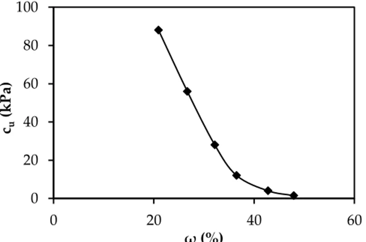
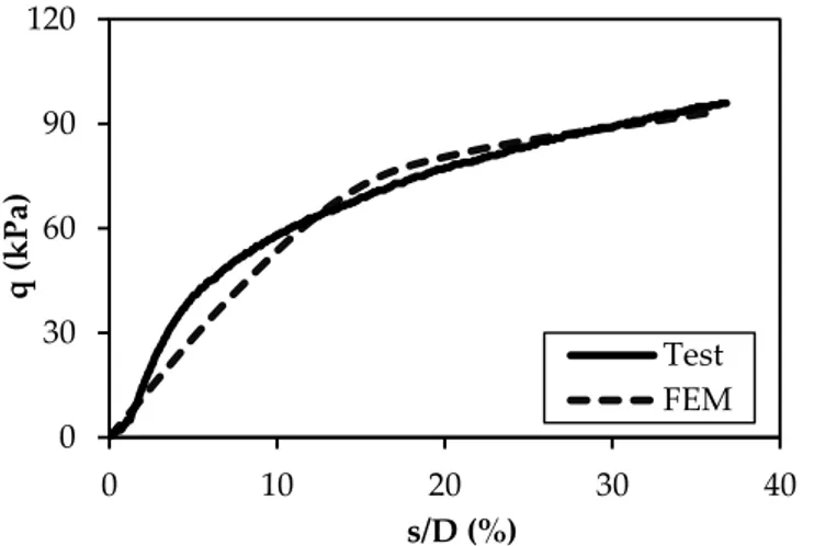
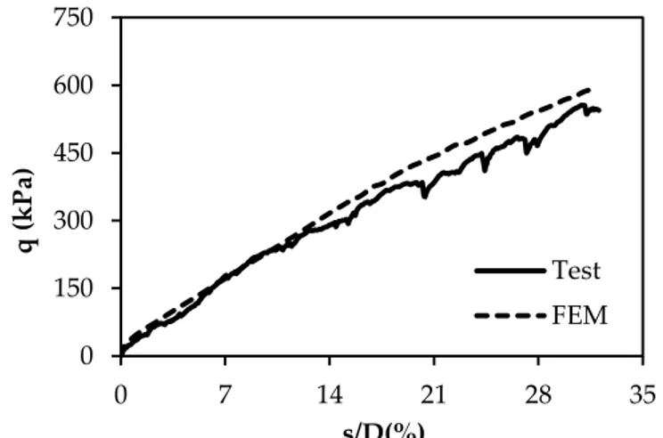
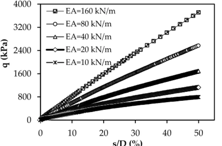
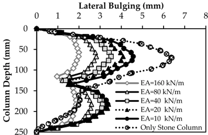
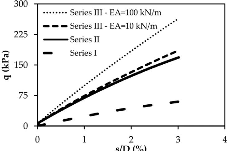
(kPa) Static.. Thus, by decreasing the diameter of stone columns, the depth of the maximum value of bulging decreased. Through keeping accurate observation on the maximum

One of the major challenges among engineers is to construct various types of structures over weak soils. Among various technologies implemented by engineers, stone

Analyzing  Big  Data  requires  a  vast  amount  of  storage  and  computing  resources.  We  need  to  untangle  the  big,  puzzling  information  we  have 

Nature of the Seismic Stresses: The structural components like walls, columns and beams. Before the earthquake, these elements can only carrying the vertical loads. But it will

Bu nedenle, fiziksel yöntemlerin etkin olmadığı durumlarda ve/veya yüksek saflıkta kuvars üretmek için liç gibi çeşitli asit çözeltilerinin kullanıldığı kimyasal

The aim of this study is to understand the reasons for the changes occurring in labour organisations and work- manship in Turkey through a study based on workers’ experiences. The

Birko dışındaki tüm fabrikalarda beş yıl ve altında çalışanların yoğunlukta olması hipotezlerimizden biri olan, fabrika sahiplerinin kıdem tazminatı ve

Fail, şaka amacı ile de gerçekleştirmek istediği hareketin neticesinin suç teşkil ettiğini öngörüyorsa ve buna rağmen hareketine devam ediyorsa, failin gerçekleşecek