EFFECT OF DIFFERENT WALL FUNCTIONS ON THE PREDICTION OF FLOW AND HEAT TRANSFER CHARACTERISTICS IN PLATE FIN AND TUBE HEAT EXCHANGERS
Azize AKKOCA1 Beşir ŞAHİN2 and Mustafa TUTAR1
1Mersin University, Department of Mechanical Engineering, MERSIN / TURKIYE 2Çukurova University, Department of Mechanical Engineering, ADANA / TURKIYE
Makalenin Geliş Tarihi: 12.01.2005
ABSTRACT: In the present study, effects of wall functions available in the Fluent software on the fluid
flow and heat transfer characteristics of a plate fin and tube heat exchanger are investigated in the range of 500≤Re≤6000 for a non-dimensional fin spacing of Fs =0.233 and the results are compared with experimental data. As it is well-known, wall functions are used to bridge the viscosity-affected region between the wall and the fully turbulent region in the flow domain. Both Standard k-ε and RNG k-ε turbulence models are employed in order to predict the flow and heat transfer characteristics inside the flow passage of the plate fin and tube heat exchanger comprised of four-row of staggered tube layout with wavy fin configuration. The test heat exchanger model is selected from the experimental work exists in the literature and the best wall function that has close agreement with the experimental data is chosen as Enhanced Wall Treatment.
Key Words: Turbulence models, wall functions, plate fin and tube heat exchangers.
Kanat – Borulu Isı Eşanjörlerinin Akım ve Isı Transfer Özelliklerinin Belirlenmesinde Farklı Duvar Fonksiyonlarının Etkisi
ÖZET: Bu çalışmada, Fluent yazılım programında mevcut bulunan duvar fonksiyonlarının, kanat
borulu ısı eşanjörlerinde akım ve ısı transfer özelliklerinin belirlenmesindeki etkileri Reynolds Sayılarının 500≤Re≤6000aralığında ve Fs =0.233 boyutsuz plaka açıklığında araştırılmış ve sonuçlar deneysel çalışma ile karşılaştırılmıştır. Bilindiği üzere duvar fonksiyonları, viskoziteden etkilenmiş bölge ile tamamen türbülanslı akışın hakim olduğu bölge arasında bir köprü görevi kurmaktadır. Dö sıralı, saptırmalı boru konfigürasyonuna ve dalgalı plakaya sahip bir kanat- borulu ısı eşanjöründeki akış ve ısı transfer özelliklerinin belirlenmesinde Standard k-ε and RNG k-ε türbülans modelleri kullanılmıştır. Bu ısı eşanjör modeli literatürdeki bir deneysel çalışmadan alınmış ve deneye en yakın sonucu veren duvar fonksiyonu İyileştirilmiş Duvar Fonksiyonu olarak belirlenmiştir.
Anahtar Kelimeler: Türbülans modelleri, duvar fonksiyonları, kanat-borulu ısı eşanjörü.
INTRODUCTION
The plate fin and tube heat exchangers that consist of plain or specially configured parallel fins located on the outside of the tube bundle result in a very complex geometry. This complex geometry causes formation of a highly complex and three dimensional flow and heat transfer characteristics. This complex flow behavior includes developing velocity and thermal
boundary layers at the channel entrances; continuous creation, destruction, separation and reattachment of new boundary layers due to the presence of the fins and the existence of large amount of tubes; formation of horseshoe vortices in front of the tubes; interaction of secondary flows of opposite vorticity at the front and sides of the tubes; recirculating tube wakes; vortices in the wake of the fins; improved air mixing and thinning of boundary layers along with lateral
swirl mixing due to the corrugated geometry formed by the wavy fins. Saboya and Sparrow (1974), and Goldstein and Sparrow (1976) measured local and average heat transfer coefficients using naphthalene mass transfer technique for various heat exchanger models. Seshimo and Fujii (1991), and Kim et al. (1997), investigated effect of geometrical parameters such as fin spacing, fin length, fin configuration, tube diameter, distance between tubes, and tube row number on the heat transfer and friction performance of heat exchangers in the range of 300<Re<2000. Madi et al. (1998), Yan and Sheen (2000), Lozza and Merlo (2001), Valencia et al. (1996), conducted wind tunnel tests to investigate the heat exchanger performance. Critoph at al. (1999) measured local heat transfer coefficient on the fin and compared steady state and transient measurement results by using liquid crystal thermography. Some investigators including Barsamian and Hassan (1997), Rocha et al. (1997), Wung and Chen (1989), Mendez at al. (2000) performed numerical studies to understand flow details that occur in the heat exchanger passages. According to Kundu et al. (1992), for the plate fin and tube heat exchangers, the flow attains turbulent characteristics when the Reynolds number is larger than 400 based on their pressure measurements and numerical calculations. Shah et al. (1997) indicated that for plate fin and tube heat exchangers, there is no clear evidence yet that the flows in the operating Reynolds number range (100<Re<2000) are
unsteady laminar or low Reynolds number turbulent flows; although it is possible that gradually the unsteady laminar flows associated with the interruptions become low Reynolds number turbulent flows. Turbulent flows are significantly affected by the presence of walls. The mean velocity field is affected through the no-slip condition that has to be satisfied at the wall. The turbulence is also changed by the presence of the wall. Very close region to the wall, viscous damping reduces the tangential velocity fluctuations, while kinematic blocking reduces the normal fluctuations. Toward the outer part of the near wall region, the turbulence is rapidly augmented by the production of turbulent kinetic energy due to the large gradients in mean velocity. Accurate representation of the flow in the near wall region determines successful predictions of wall-bounded turbulent flows (FLUENT, 1998).
Numerous experiments have shown that the near-wall region can be largely subdivided into three layers. In the innermost layer, called the “viscous sublayer”, the flow is almost laminar, and the (molecular) viscosity plays a dominant role in momentum and heat or mass transfer. In the outer layer, called the fully-turbulent layer, turbulence plays a major role. Finally, there is an interim region between the viscous sublayer and the fully turbulent layer where the effects of molecular viscosity and turbulence are equally important.
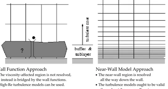
Wall Function Approach Near-Wall Model Approach
• The viscosity-affected region is not resolved, • The near-wall region is resolved instead is bridged by the wall functions. all the way down the wall.
• High-Re turbulence models can be used. • The turbulence models ought to be valid
throughout the near-wall region.
Figure 1. Near-wall treatments (FLUENT, 1998). Şekil 1. Yakın-cidar uygulamaları (FLUENT, 1998).
Traditionally, two approaches for modeling the near-wall region are given in Fig. 1. In one approach, the viscosity-affected inner region (viscous sublayer and buffer layer) is not resolved. Instead, semi-empirical formulas called “wall functions” are used to bridge the viscosity-affected region between the wall and the fully-turbulent region. The use of wall functions obviates the need to modify the turbulence models to account for the presence of the wall. In most high-Reynolds-number flows, the wall function approach substantially saves computational resources, because the viscosity-affected near-wall region, in which the solution variables change most rapidly, does not need to be resolved. The wall function approach is popular because it is economical, robust, and reasonably accurate. The wall functions comprise;
• laws-of-the-wall for mean velocity and temperature (or other scalars),
• formulas for near-wall turbulent quantities. FLUENT offers three choices of wall function approaches (FLUENT, 1998):
• standard wall functions, • non-equilibrium wall functions, • enhanced wall treatment.
Wall effects can also be taken into account by using a very fine mesh near the solid walls in order to properly resolve the sublayer. The first grid point must be placed in either the viscous sublayer or in the inertial sublayer.
It is known that wavy fins accelerate the air flow and intensifies the turbulence of the air flow and enhance the heat transfer rate (Madi et al., 1998). According to Tzanetakis et al. (2004), boundary layers continuously created and destroyed due to the corrugation geometry of the wavy fins result in improved air mixing. The surface waviness-induced periodic disruption and thinning of boundary layers along with lateral swirl mixing produce high local heat fluxes near the wall peak regions (Zhang et al., 2004). Therefore in the present study, all of the wall functions available in the FLUENT finite volume code are tested and heat transfer as well as pressure drop results are compared with the experimental data and the best wall model is determined.
NUMERICAL STUDY
Numerical Method
In the present study, all simulations are carried out by using FLUENT finite volume code written in the C computer language. FLUENT solves the governing integral equations for the conservation of mass, momentum, energy, and for other scalars such as turbulence and chemical species by using finite volume based technique. In the finite volume method the solution domain is sub-divided into a finite number of discrete continuous control volumes and the conservation equations are applied to each control volume. The governing conservation equations are integrated on the individual control volumes to construct the algebraic equations for the discrete dependent variables such as velocity, pressure, temperature, and scalars. The discretized equations are linearized and the resultant linear system of equations are solved to yield updated values of the dependent variables. In the present investigation, the segregated solution method is used to solve the governing integral equations for the conservation of mass, momentum, and energy. All fluid properties including density, viscosity, specific heat, and conductivity are assumed constant. In all simulations, second order upwind scheme is used for higher order accuracy to be achieved. The under relaxation factors are set as 0.2, 0.5, and 0.9 for pressure, momentum, and energy, respectively. The convergence criterion for the continuity and momentum equations is set as 10-3 while it is set as 10-6 for the energy residual.
Governing Equations for Fluid Flow and Heat Transfer in the Plate Fin and Tube Heat Exchangers
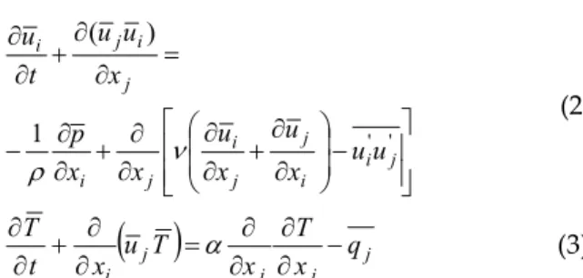
In the absence of external body forces, for a three-dimensional, incompressible and Newtonian fluid of constant density and constant viscosity, the governing time averaged continuity, momentum and energy conservation equations respectively take the following forms:
0 = ∂ ∂ i i x u (1)
− ∂ ∂ + ∂ ∂ ∂ ∂ + ∂ ∂ − = ∂ ∂ + ∂ ∂ ' ' 1 ) ( j i i j j i j i j i j i u u x u x u x x p x u u t u ν ρ (2)
( )
j j j j i q x T x T u x t T − ∂ ∂ ∂ ∂ = ∂ ∂ + ∂ ∂ α (3) Reynolds averaging introduces additional terms in the momentum and energy equations which are known as “Reynolds (turbulent) stress”, −ρui'u'j , and the “Reynolds (turbulent) heat flux”, −qj, which appear on the right- hand side of the momentum and the energy equations, respectively. The task of turbulence modeling is to model these unknowns, higher-order, extra terms in the mean flow equations and thus close the system of equations.Computational Domain and Boundary Conditions
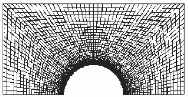
In the present study, a heat exchanger model having dimensions of Fs = 0.233, Lf =19.05, W = 12.7, Dc=10.3 mm (Fig. 2) and comprised of 4 rows of staggered tube layout, and having wavy fin configuration is selected from the experimental study (sample no: 8), Wang et al. (1997). The geometry and the mesh distribution of this sample heat exchanger are developed using Fidap finite element code and imported to the fluent finite volume code. All physical properties, boundary conditions and flow characteristics are set up in the experimental data. The grid independency tests are carried out by using different number of grid nodes distributed along the x, y, and z-axes in order to test the effect of grid distribution as well as grid independency in the computational domain. Figure 3 illustrates detail of mesh around the
cylinder surface for the selected heat exchanger model.
During the grid generation, the 3-dimensional geometry of the domain is decomposed into 2-dimensional sub-surfaces. Then, the finite element mesh is generated on each surface and throughout the flow domain. The three-dimensional finite element mesh with eight-noded brick elements are used to mesh the whole computational domain while four-noded quadrilateral control volume elements are used to mesh the sub-surfaces. At the cylinder and the tube wall surfaces, and in regions close to those surfaces, a very fine mesh is used in order to accurately resolve the pressure, velocity, and temperature gradients adjacent to those regions. 207162 nodes are used to mesh the whole computational domain.
All simulations are carried out by considering the following velocity and temperature boundary conditions: Inlet velocity boundary conditions are used at the inflow section to define the velocity and temperature of the flow at inlet boundaries. It is assumed that only a constant and uniform streamwise-direction velocity component exists and other velocity components are assumed to be zero. The outflow boundary condition is used to model the flow exit where the details of the flow velocity and pressure are not known prior to solution of the flow problem. Wall boundary condition is used to bound fluid and solid regions at the fin and tube surfaces: The boundary conditions are no-slip
(
u=v=w=0)
and costant temperature at the solid walls. Wall temperature is set to a value of 65 °C as in the related experimental study. Symmetry boundary conditions at the symmetry zones which are also known as the repeating boundaries are used to reduce computational effort.Figure 2. Schematic representation of the geometrical parameters for the four rows of staggered tube layout and wavy fin configuration.
Şekil 2. Dalgalı plaka ve 4-sıralı saptırmalı dizilişe sahip boru konfigürasyonu
Figure 3. Detail of mesh around the cylinder.
Şekil 3. Silindir etrafındaki ağ yapısının detayı Turbulence Models
The Standard k-ε and the RNG k-ε turbulence models are used to predict the flow and heat transfer characteristics occuring in the plate fin and tube heat exchanger flow passage.
Standard k-ε Turbulence Model: In this model,
the turbulent viscosity is correlated with the turbulent kinetic energy (k) and the dissipation rate of turbulent kinetic energy (ε) obtained from the following transport equations:
ε ν σ ν − ∂ ∂ ∂ ∂ + ∂ ∂ + ∂ ∂ ∂ ∂ = j i i j j i t j k eff j x u x u x u x k x Dt Dk (4) k C x u x u x u k C x x Dt D j i i j j i t j eff j 2 2 1 ε ν ε ε σ ν ε ε − ∂ ∂ ∂ ∂ + ∂ ∂ + ∂ ∂ ∂ ∂ = (5)
where ν is the effective kinematic viscosity, eff t
eff ν ν
ν = + . The constants in the above
equations are σk =1.0, σε =1.3, C1=1.44, 92
. 1 2 =
C . The turbulent kinematic viscosity is
computed by ε ν µ 2 k C t= (6) where Cµ =0.09.
RNG k-ε Turbulence Model: The
Renormalization Group (RNG) k-ε model differs from the standard model by the inclusion of an additional sink term in the turbulence
dissipation equation to account for non-equilibrium strain rates and employs different values for the various model coefficients. The form of the k equation remains same. The turbulence dissipation, ε equation of the RNG k-ε model includes the following sink term
(
)
k n C 2 3 3 1 1 0 ε β η ηη µ + − (7)In the above term the extra term employs the parameter η, which is the ratio between the charesteristic time scales of turbulence and mean flow field as follows:
ε
η
=Sk where t ij ijS G S S= 2 = µ ∂ ∂ + ∂ ∂ = i j j i ij x u x u S 2 1 (8)The primary model coefficients of the RNG
k-ε turbulence model are Cµ, C1, C2,, σk , σεand
Von Karman constant
κ
. Recommended values of this model coefficients are as follows:3875 . 0 , 7179 . 0 , 7179 . 0 , 68 . 1 , 41 . 1 C , 085 . 0 1 2 = = = = = = κ σ σ ε µ k C C (9)
RESULTS AND DISCUSSION
It is known that wall functions are used to bridge the viscosity-affected region between the wall and the fully turbulent region. In FLUENT, three different wall functions are available: i) Standard Wall Function, ii) Enhanced Wall Function, and iii) Non-equilibrium Wall Function. Figures 4 and 5 show pressure drop coefficient, K, as a function of Reynolds number obtained from Standard k-ε and RNG k-ε turbulence model simulations, respectively. The coefficient of pressure drop is calculated as
2 2 1 ∞ ∞− = U p p K exit ρ (10)
wherep and ∞ pexit are the pressures at the inlet and exit sections of the heat exchanger,
respectively and U is the free stream velocity. ∞ These pressures are obtained by firstly creating iso-surfaces at the inlet and outlet sections of the heat exchanger, secondly, getting average static pressures at the specified surfaces using Eq. 11. From figures 4 and 5, it is clear that K decreases as the Reynolds number increases. The Non-equilibrium wall function gives higher K values while the Enhanced wall function gives lower K values compared to the other wall functions for Standard k-ε turbulence model simulation (Fig. 4). There is no significant difference between Standard and Enhanced wall functions on the determination of the K when Re≥3000 for RNG k-ε turbulence model as shown in Fig. 5.
The average heat transfer coefficients are considered as the area-weighted averaged values of these data and are computed by the present finite volume code for both the fin and the tube surfaces from the computation of the surface integrals at the specified surfaces as follows:
∫
=
∑
=n i i iA
A
dA
A
11
1
φ
φ
(11)where φi is the selected field variable for the flow or heat transfer, A is the total surface area and Ai is the heat transfer surface area. It is clear from Fig. 6 that average heat transfer coefficient increases as the Reynolds number increases. Higher heat transfer coefficient values are obtained from Non- equilibrium wall function compared with the Standard and Enhanced wall
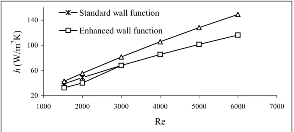
functions for the Standard k-ε turbulence model. Non-equilibrium wall function gives higher average heat transfer coefficients for the RNG k-ε turbulence model simulation. When Re≥3000, the Standard and Enhanced wall functions give very similar results in the calculation of average heat transfer coefficients as shown in Fig. 7.
The friction factor f is known as a good design parameter for the plate fin and tube heat exchangers since it determines the pressure drop across the heat exchanger It is calculated as follows: ) ( 2 f s exit L F U p p f ∞ ∞ − = ρ (12)
In Figs. 8 and 9, the calculated values for the friction factor (f) as a function of the Reynolds number are presented for the Standard k-ε and RNG k-ε turbulence models, respectively. The experimental data of Wang et al. (1997) are also included for the sake of comparison. All numerical model simulation results overestimate the experimental result. It is clearly seen in these figures that the wall function that has close agreement with the experimental data is the Enhanced wall function.
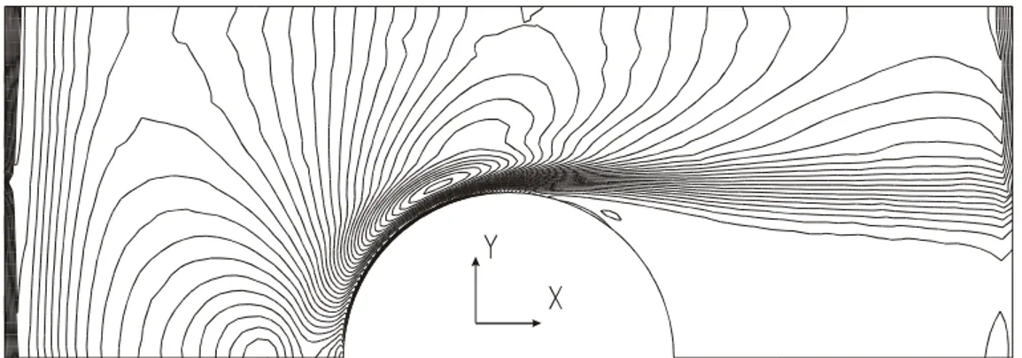
Figure 10 illustrates averaged vorticity contours around the first cylinder at Re = 1500 obtained from RNG k-ε turbulence model simulation. The flow is in the X- direction. The location of the horseshoe vortex system in the forward part of the cylinder is clearly seen. 4 6 8 10 12 14 1000 2000 3000 4000 5000 6000 7000
Re
K
Standard wall function Enhanced wall function Non-equilibrium wall function
Figure 4. Pressure drop coefficient between the inlet and outlet sections of the heat exchanger
as a function of Reynolds number obtained from Standard k-ε turbulence model simulation.
Şekil 4. Isı eşanjörünün giriş ile çıkışı arasındaki basınç kayıp katsayısının Reynolds sayısı ile
4 6 8 10 12 14 1000 2000 3000 4000 5000 6000 7000
Re
KStandard wall function Enhanced wall function Non-equilibrium wall function
Figure 5. Pressure drop between the inlet and outlet sections of the heat exchanger
as a function of Reynolds number obtained from RNG k-ε turbulence model simulation.
Şekil 5. Isı eşanjörünün giriş ve çıkışı arasındaki basınç kayıp katsayısının Reynolds sayısı ile
değişiminin RNG k-ε türbülans modeli simülasyonlarından elde edilen sonuçları.
20 60 100 140 1000 2000 3000 4000 5000 6000 7000 Re h (W/m 2 K)
Standard wall function Enhanced wall function
Figure 6. Heat transfer coefficient as a function of Reynolds number obtained
from Standard k-ε turbulence model simulation.
Şekil 6. Isı transfer katsayısının Reynolds sayısı ile değişiminin Standart k-ε türbülans modeli
simülasyonlarından elde edilen sonuçları.
20 60 100 140 1000 2000 3000 4000 5000 6000 7000 Re h (W/m 2 K)
Standard wall function Enhanced wall function
Figure 7. Heat transfer coefficient as a function of Reynolds number obtained
from RNG k-ε turbulence model simulation.
Şekil 7. Isı transfer katsayısının Reynolds sayısı ile değişiminin RNG k-ε türbülans
0 0.05 0.1 0.15 0.2 0 1000 2000 3000 4000 5000 6000 7000 Re f
Standard wall function Enhanced wall function Non-equilibrium wall function EXP (Wang et al., 1997)
Figure 8. Friction factor as a function of Reynolds number obtained from
standard k-ε turbulence model simulation.
Şekil 8. Sürtünme katsayısının Reynolds sayısı ile değişiminin Standart k-ε
türbülans modeli simülasyonlarından elde edilen sonuçları.
0 0.05 0.1 0.15 0.2 0 1000 2000 3000 4000 5000 6000 7000 Re f
Standard wall function Enhanced wall function Non-equilibrium wall function EXP Wang et al., 1997)
Figure 9. Friction factor as a function of Reynolds number obtained from
RNG k-ε turbulence model simulation.
Şekil 9. Isı transfer katsayısının Reynolds sayısı ile değişiminin RNG k-ε türbülans
modelisimülasyonlarından elde edilen sonuçları.
Figure 10. Averaged vorticity contours around the first cylinder for
Re=1500 obtained from RNG k-ε turbulence model simulation.
Şekil 10. Re=1500 için ilk silindir etrafındaki ortalama girdap dağılımının RNG k-ε
3rd cylinder 4th cylinder
Figure 11. Averaged velocity vectors and corresponding streamline patterns around the third
and the fourth cylinders for Re=1500 obtained from RNG k-ε turbulence model simulation.
Şekil 11. Re=1500 için üçüncü ve dördüncü silindirler etrafındaki ortalama hız vektörleri ve akım
çizgilerinin RNG k-ε türbülans modeli simülasyonlarından elde edilen sonuçları.
Figure 11 shows averaged velocity vectors and corresponding streamline patterns around the third and the fourth cylinders obtained from RNG k-ε turbulence model simulation for Re = 1500. It can be seen that horseshoe vortex system forms upstream of the third and the fourth cylinders and a recirculation region occurs downstream of the fourth cylinder.
CONCLUSIONS
The Standard k-ε and the RNG k-ε turbulence models are employed to determine pressure drop and heat transfer coefficients in
the plate fin and tube heat exchanger flow passage. It is found that heat transfer coefficients increase and pressure drop coefficients decrease as the Reynolds number increases. Simulation results for the Standard k-ε and the RNG k-ε turbulence models show that Non-equilibrium wall function gives higher pressure drop and heat transfer coefficients comparing to the other wall functions. When different wall function results for friction factor are compared with each other, the Enhanced wall function gives better agreement with the experimental data compared with the Standard and the Non-equilibrium wall functions.
REFERENCES
Barsamian, H.R., Hassan, Y.A., 1997, Large Eddy simulation of turbulent crossflow in tube bundles, Nucl. Eng. Des., 172,103-122.
Critoph, R.E., Holland, M.K., Fisher, M., 1999, Comparison of steady state and trasnsient methods for measurement of local heat transfer in plate fin-tube heat exchangers using liquid cristal thermography with radiant heating, Int. J. Heat Mass. Tran., 42, 1-12.
FLUENT DYNAMICS SOFTWARE, 1998, FLUENT (Ver. 5.5).
Goldstein, L.G., Sparrow, E.M., 1976, Experiments on the transfer characteristics of a corrugated fin and tube heat exchanger configuration, J. Heat. Trans.-T. ASME, 98, Feb., 26-34.
Kim, N.H., Yun, J.H., Webb, R.L., 1997, Heat transfer and friction correlations for wavy plate fin- and- tube heat exchangers, Transactions of the ASME, 119, 560-567.
Kundu, D., Skeikh, A.H., Lou, D.Y.S., 1992, Heat transfer in crossflow over cylinders between two parallel plates, Numer. Heat Tr. A-Appl., 114, 558-564.
Lozza, G., Merlo, U., 2001, An experimental investigation of heat transfer and friction losses of interrupted and wavy fins for fin-and-tube heat exchangers, Int. J. Refrig., 24, 409-416.
Madi, M.A., Johns,R..A.,Heikal, M.R., 1998, Performance characteristics correlation for round tube and plate finned heat exchangers, Int. J. Refrig., 21, 7, 507-517.
Mendez, R.R., Sen, M., Yang, K.T., Mcclain, R., 2000. Effect of fin spacing on convection in a plate fin and tube heat exchanger, Int. J. Heat Mass. Tran., 43, 39-51.
Rocha, L.A.O., Saboya, F.E.M., Vargas, J.V.C., 1997, A comparative study of elliptical and circular sections in one- and two- row tubes and plate fin heat exchangers, Int. J. Heat Fluid Fl., 18, 247-252.
Saboya, F.E.M., Sparrow, E.M., 1974, Local and average transfer coefficients for one row plate fin and tube heat exchanger configurations. J. Heat Transfer, Trans. ASME., August: 265-272.
Seshimo, Y., Fujii, M., 1991, An experimental study on the performance of plate fin and tube heat exchangers at low Reynolds Numbers, ASME/JSME Thermal Engineering Proceedings, 4, 449-454.
Shah, R.K., Heikal, M.R., Thonon, B., 1997, Advances in numerical analysis of fluid flow, heat transfer, and flow friction characteristics of compact heat exchanger surfaces, Proceedings, Int. Symposium on Fluid Flow and Heat Transfer, Ankara, Turkey, 68-87.
Tzanetakis, N., Scott, K., Taama, W.M., Jachuck, R.J.J., 2004. Mass transfer characteristics of corrugated surfaces, Appl. Therm. Eng., 24, 13,1865-1875.
Valencia, A., Fiebig, M., Mitra, N.K., 1996, Heat transfer enhancement by longitudinal vortices in a fin- tube heat exchanger element with flat tubes, J. Heat Trans., 118, 209-211.
Wang, C.C., Fu, W.L., Chang, C.T., 1997, Heat transfer and friction characteristics of typical wavy fin- and- tube heat exchangers, Exp. Therm. Fluid Sci., 14, 174-186.
Wung, T.S., Chen, C.J., 1989, Finite analytic solution of convective heat transfer for tube arrays in crossflow: Part I- Flow field analysis, J. Heat Trans., 111, 633-640.
Yan, W.M., Sheen, P.J., 2000, Heat transfer and friction characteristics of fin and tube heat exchangers, Int. J. Heat Mass Trans., 43, 1651-1659.
Zhang, J., Kundu, J., Manglik, R.M., 2004, Effect of fin waviness and spacing on the lateral vortex structure and laminar heat transfer in wavy-plate-fin cores, Int. J. Heat Mass Trans., 47, 1719-1730.