Enhanced directed emission from metamaterial based radiation source
Elena Saenz, Kaan Guven, Ekmel Ozbay, Iñigo Ederra, and Ramon Gonzalo
Citation: Appl. Phys. Lett. 92, 204103 (2008); View online: https://doi.org/10.1063/1.2931027
View Table of Contents: http://aip.scitation.org/toc/apl/92/20
Published by the American Institute of Physics
Articles you may be interested in
Anisotropic metasurface with near-unity circular polarization conversion
Applied Physics Letters 108, 183502 (2016); 10.1063/1.4948594
Adaptable metasurface for dynamic anomalous reflection
Applied Physics Letters 110, 201904 (2017); 10.1063/1.4983782
Ultra-wideband and high-efficiency polarization rotator based on metasurface
Applied Physics Letters 109, 051901 (2016); 10.1063/1.4960355
Polarization conversion of metasurface for the application of wide band low-profile circular polarization slot antenna
Applied Physics Letters 109, 054101 (2016); 10.1063/1.4960198
Experimental realization of negative refraction using one metasurface
Applied Physics Letters 106, 121903 (2015); 10.1063/1.4916369
Realization of spin-dependent splitting with arbitrary intensity patterns based on all-dielectric metasurfaces
Enhanced directed emission from metamaterial based radiation source
Elena Saenz,1,a兲Kaan Guven,2Ekmel Ozbay,2Iñigo Ederra,1and Ramon Gonzalo11
Electrical and Electronic Engineering Department, Public University of Navarra, Campus Arrosadia, E-31006 Pamplona, Spain
2
Nanotechnology Research Center-NANOTAM, Department of Physics, Department of Electrical and Electronics Engineering, Bilkent University, 06800 Ankara, Turkey
共Received 7 December 2007; accepted 25 April 2008; published online 23 May 2008兲
The enhanced directed emission from a metasurface which is illuminated at its resonance frequency by a dipole source is experimentally demonstrated. The metasurface consists of two cutwire layers and a continuous wire layer in between, which exhibits strong magnetic dipole resonance under excitation normal to the plane. The scanned near-field patterns show the confinement of the field in the presence of metasurface, which, in turn, provides an enhanced and directional radiation in the far field. The far-field patterns are obtained by direct measurement and by a far-field transformation of the scanned near field, which are found to be in good agreement. © 2008 American Institute of Physics. 关DOI:10.1063/1.2931027兴
Artificial dielectrics, implemented, e.g., as arrays of wires, have been used for decades as lightweight beam shap-ing elements. It is nowadays well understood that some elec-tromagnetic共photonic兲 crystals simulate the behavior of ho-mogeneous materials with ultralow refractive index near stop-band edges.1,2This observation has led to several stud-ies concerning directive radiating source design using such periodical structures to shape the beam of a low-gain primary radiator.3 It is also known that a slight local change in the period of electromagnetic crystals leads to localized resonant modes which can be used for the realization of devices radi-ating energy in a very narrow angular range.4 Typically, ra-diating sources are placed inside Fabry–Perot resonant cavi-ties formed by removal of rows of wires or dielectric rods in a periodical lattice.5,6 Similarly, partially reflective surfaces in combination with ground planes have been used to create Fabry-Perot-like cavities7 for enhanced radiation purposes. The use of superstrates on top of radiating sources is another well-known gain enhancement tool.8As in the case of de-fected electromagnetic crystal structures5,6 one of the key ideas of different superstrates is to allow radiation from a primary source to spread over a larger radiating aperture, and therefore enhancing the directivity. Recently, very exotic structures such as material covers or superstrates aimed to possess double-negative behavior9–12have been proposed for this aim.13–16
The solution proposed herein is based on the property of metamaterials for enhancing the radiation performance of sources by virtue of their ability to control the propagation 共and suppression兲 of electromagnetic waves. It is conceptu-ally different from the previous topologies, since no cavity or ground plane are required. We employ the metamaterial in the form of a multilayer metasurface that is placed in close proximity to the radiating source acting as superstrate. When working at the transmission pass band of the metasurface, magnetic dipole moments are induced in the superstrate in-clusions which enhance the emission.14–17
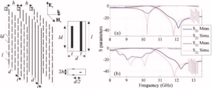
The metasurface that was used in this work is schemati-cally shown in Fig. 1 and has been described in detail in Refs.14–16. It based on the so-called cutwire/wire elements
used in planar left-handed metamaterials,9–12 where the cutwire and wire layers provide negative permeability and negative permittivity, respectively, so that the composite me-dium acts as an effective meme-dium with negative index of refraction. The operation of the metamaterial can be heuris-tically explained in the following manner:16,17 Under normal incident plane-wave excitation, at the resonant frequency 共fr兲, out-of-phase currents are induced in the pairing dipoles that are seated in layers 1 and 3. Therefore, a compensation of the total current in the slab is obtained allowing the inci-dent wave to propagate through the grids. Since the distance h between the layers is very small compared to the wave-length, a closed current loop is formed that creates a strong magnetic dipole moment that produces radiation, i.e., a trans-mission window appears 关see Fig. 1共a兲 兩BW兩S
11=−10 dB
=⌬f / f0= 4%兴. To widen the pass band, a grid of solid wires is placed in between the dipole grids.16 In this case, two modes appear due to the capacitances and mutual coupling between the cutwires and the continuous wires. Since the wires are in the symmetry plane of the cutwires but shifted, the first mode is not disturbed. There are now two possibili-ties for the currents in the grids to cancel each other and by properly choosing the unit cell dimensions both transmission bands can be merged together enlarging the pass band 共8.8–10.3 GHz兲 关see Fig.1共b兲 兩BW兩S
11=−10 dB= 16%兴.
In the present work, the metasurface is illuminated by a dipole source which is placed below the central cutwire of
a兲Electronic mail: [email protected].
FIG. 1.共Color online兲 Schematic representation of the metasurface, and unit cell geometry: top and lateral views. Right panel: the simulated and mea-sured transmission and reflection spectra through 共a兲 the double grid of cutwires and共b兲 in the presence of the continuous wires.
APPLIED PHYSICS LETTERS 92, 204103共2008兲
the metasurface 共see Fig. 3兲. In that case, the currents
in-duced in the cutwires are in phase with the source currents, so that the metasurface can be placed close to the source without loosing radiation efficiency.15Owing to the in-phase oscillation of the metasurface inclusions, uniform illumina-tion of a larger radiating area is obtained and therefore en-hanced emission. The radiation performance of such a con-figuration were tested by means of far-field 共FF兲 measurements and subsequently compared with the near-field共NF兲 measurements.
In order to numerically estimate the gain enhancement, FF measurements of the radiating metasurface integrated to the dipole were performed. Simulations and measurements of the input impedance matching and gain of the dipole source with the superstrate are shown in Fig.2. The gain was calculated by comparing the received power with our source plus metasurface and with a gain-known standard gain horn. A gain enhancement window similar to the transmission one presented in Fig. 1 is observed, but shifted upwards 共9.9–10.7 GHz兲 due to the different excitation of the meta-surface, dipole source instead of plane wave. At 10.5 GHz, an input impedance matching of −17 dB and a gain value of 6.8 dB were measured, which implies a 4.6 dB gain en-hancement with respect to a plain dipole source. Taking into account the overall physical size of the superstrate 共⬃1⫻0.5兲, and by applying G=4/apAphy, 82% aper-ture efficiency 共ap兲 is achieved, ap being the ratio of the effective radiating area to the physical size of the aperture, in this case, the metasurface. Notice that a ground plane is not used in the radiating structure; the metasurface superstrate can effectively confine and direct the radiation in the desired propagation direction.
The NF profile of the radiation gives direct insight on how the coupling between the metasurface and the source affects the resulting radiation performance. Here, the electric field distribution of the dipole was measured by using a NF scanner and was then compared to the one emitted with the
metasurface. The probe, which was a monopole antenna, was mounted over a two-dimensional scanning system and placed /5 far away from the antenna. The distance from the meta-surface to the probe z0 was chosen so that the probe was close enough to detect the surface illumination but out of the reactive NF of the antenna, which is usually taken as/2. Since z0 is smaller than , the sample points ⌬x and ⌬y should be chosen to be smaller than /2兵⌬x,⌬y =/关2
冑
1 +共/z0兲2兴其 in order to satisfy the sampling criteria.18 For a working frequency of 10.5 GHz and z0 =/5, the sampling step should be around /10, and there-fore,⌬x and⌬y were fixed to 3 mm. The size of the meta-surface is ⬃1⫻0.5 and the NF scan area is ⬃3⫻3. The radiated electric field is shown to be along the metal strips and, therefore, the probe was oriented parallel to them. Details of the probe orientation regarding the antenna are shown in Fig. 3. In order to feed the dipole/metasurface structure and detect the field by the probe, a network ana-lyzer共HP8510C兲 was used.The intensity maps of the scanned field, when the dipole was radiating in free space and in the presence of the meta-surface, are shown in Figs. 3共a兲 and3共b兲. Due to the cou-pling between the metasurface and the dipole source, the fr of the dipole is shifted from 9.51 GHz in free space to 10.5 GHz with the metasurface. In the absence of superstrate 共a兲, the regular free space radiation of a dipole is confirmed, i.e., broad beam in the H plane and nulls in the endfire di-rection corresponding with the E plane. When the metasur-face is placed atop the dipole共b兲, the radiated field is con-fined by the superstrate and radiated in the boresight radiation in turn producing the gain enhancement. Moreover, a reduction in the endfire radiation in obtained all around the antenna.
To gain more insight in the electromagnetic response of the metasurface, the NF patterns were measured at the other significant points of the gain curve, i.e., below the gain en-hancement window 共9.51 GHz兲, at the first gain peak 共10.23 GHz兲, at the second gain peak 共10.5 GHz兲, and over the gain enhancement window共11.43 GHz兲. At the frequen-cies that are out of the gain enhancement window关Figs.4共a兲
and4共c兲兴, the metasurface is suppressing the radiation, since the dipole source is operating at the metasurface’s stop band. No magnetic dipole moments are excited and, therefore, no radiation is observed. At 10.23 GHz 关Fig. 4共b兲兴, more uni-form illumination of the metasurface, and therefore, some gain enhancement is obtained, but still the endfire radiation is not completely suppressed. The gain enhancement ob-tained at 10.5 GHz 关Fig.3共b兲兴 is due to the good input im-pedance matching of the antenna as well as the confinement of radiation that is produced by the metasurface.
FIG. 2.共Color online兲 Simulations and measurements of the 共a兲 impedance matching and共b兲 gain of the superstrate configuration.
FIG. 3.共Color online兲 Antenna configurations and scanned field at its fr.共a兲 Dipole radiating in free space; fr= 9.51 GHz. 共b兲 Dipole plus superstrate; 5⫻3 unit cells in the transversal direction, single layer in the propagation direction共out of plane兲; gain peak fr= 10.5 GHz.
FIG. 4.共Color online兲 NF measurements at 共a兲 9.51 GHz, 共b兲 10.23 GHz, and共c兲 11.43 GHz.
Finally, to validate the NF characterization, a NF to FF 共NF-FF兲 transformation18
was performed and compared with the FF results. To reduce the coupling between the probe and the metasurface, the distance z0 was increased to 3. The sampling step was⌬x,⌬y= 8 mm共/3.5兲, which satisfies the sampling criteria 共⌬x,⌬y艋/2兲. The NF scan area was ⬃7.5⫻7.5. The comparison between both results can be seen in Fig.5. The rippled behavior in the NF-FF pattern is due to the limited size of the scanned area and the absence of probe compensation, but still good agreement between both measurements is observed, which corroborates the NF mea-surements.
In conclusion, the enhancement of radiation from a di-pole source with a planar metasurface as superstrate was ex-perimentally demonstrated, where magnetic coupling of the metasurface induces a uniform illumination throughout the superstrate. The NF measurements of the electric field distri-bution on the radiating surface proved the confinement of the
power radiated within the metasurface. This, in turn, reduces the endfire radiation and improves the boresight radiation which comprise significant benefits for antenna applications.
1B. Gralak, S. Enoch, and G. Tayeb,J. Opt. Soc. Am. B 17, 1012共2000兲. 2M. Notomi,Phys. Rev. B 62, 10696共2000兲.
3S. Enoch, G. Tayeb, P. Sabouroux, N. Gurin, and P. Vincent,Phys. Rev.
Lett. 89, 213902共2002兲.
4G. Tayeb and D. Maystre,J. Opt. Soc. Am. A 14, 3323共1997兲. 5B. Temelkuran, M. Bayindir, E. Ozbay, R. Biswas, M. M. Sigalas, G.
Tuttle, and K.-M. Ho,J. Appl. Phys. 87, 603共1997兲.
6R. Biswas, E. Ozbay, B. Temelkuran, M. Bayindir, M. M. Sigalas, and
K.-M. Ho,J. Opt. Soc. Am. B 18, 1684共2001兲.
7A. P. Feresidis and J. C. Vardaxoglou,IEE Proc. Microwaves, Antennas
Propag. 148, 345共2001兲.
8N. G. Alexopoulos and D. R. Jackson,IEEE Trans. Antennas Propag. 32,
807共1984兲.
9V. M. Shalaev, W. Cai, U. K. Chettiar, H. Yuan, A. K. Sarychev, V. P.
Drachev, and A. V. Kildishev,Opt. Lett. 30, 3356共2005兲.
10J. Zhou, L. Zhang, G. Tuttle, T. Koschny, and C. M. Soukoulis,Appl.
Phys. Lett. 88, 221103共2006兲.
11K. Guven, M. D. Caliskan, and E. Ozbay,Opt. Express14, 8685共2006兲. 12J. Zhou, L. Zhang, G. Tuttle, T. Koschny, and C. M. Soukoulis,Phys. Rev.
B 73, 041101共2006兲.
13R. W. Ziolkowski and A. D. Kipple,IEEE Trans. Antennas Propag. 51,
2626共2003兲.
14E. Saenz, I. Ederra, P. Ikonen, S. A. Tretyakov, and R. Gonzalo,J. Opt. A,
Pure Appl. Opt. 9, S308共2007兲.
15E. Saenz, I. Ederra, P. de Maagt, and R. Gonzalo,Electron. Lett. 43, 850
共2007兲.
16P. Ikonen, E. Saenz, R. Gonzalo, and S. A. Tretyakov,IEEE Trans.
An-tennas Propag. 55, 2692共2007兲.
17E. Saenz, P. M. T. Ikonen, R. Gonzalo, and S. A. Tretyakov,J. Appl. Phys.
101, 114910共2007兲.
18Y. T. Looand and S. W. Lee, Antenna Handbook共J. Appel-Hansen, New
York, 1988兲. FIG. 5.共Color online兲 Comparison between the NF-FF transformed
radia-tion pattern and the FF measurements.