IOP Conference Series: Materials Science and Engineering
PAPER • OPEN ACCESS
The development of lab-on-a-chip fabricated from two molds
To cite this article: A. Pramuanjaroenkij et al 2018 IOP Conf. Ser.: Mater. Sci. Eng. 297 0120231234567890‘’“”
8th TSME-International Conference on Mechanical Engineering (TSME-ICoME 2017) IOP Publishing IOP Conf. Series: Materials Science and Engineering 297 (2018) 012023 doi:10.1088/1757-899X/297/1/012023
The development of lab-on-a-chip fabricated from two molds
A. Pramuanjaroenkij1,*, J. Bunta1, J. Thiangpadung1, S. Sansaradee1, P. Kamsopa1, S. Sodsai1, S. Vichainsan1, K. Wongpanit2, T. Maturos3, T. Lomas3, A. Tuantranont3, B. Cetin4, S. Phankhoksoong1 and A. Tongkratoke11Department of Mechanical and Manufacturing Engineering, Kasetsart University, Chalermphrakiat Sakon Nakhon Province Campus, Sakon Nakhon 47000, Thailand 2Department of Animal Science, Faculty of Natural Resources and Agro-Industry, Kasetsart University, Chalermphrakiat Sakon Nakhon Province Campus,
Sakon Nakhon 47000,Thailand
3Nanoelectronics and MEMS Laboratory, National Electronics and Computer Technology Center, 112 Thailand Science Park, Phahonyothin Road,
Khlong Nueng, Khlong Luang, PathumThani 12120,Thailand
4Microfluidics and Lab-on-a-chip Research Group, Mechanical Engineering Department İhsan Doğramacı Bilkent University, Ankara 06800, Turkey * Corresponding Author: E-mail [email protected]
Abstract. Development of diagnostic technique of microfluidic or lab-on-a-chip (LOCs) is
currently of great interest for researchers and inventors for their many advantages. It can be used as a real laboratory was many ways to help to the diagnosis faster. This research aims to develop Polydimethylsiloxane (PDMS) lab-on-a-chip (LOCs) which were produced from different molds; the silicon wafer mold and the stainless mold to investigate the flow of the biological sample as the flow in nanochannels. In addition, this research proposes a means to leakage and the blockage of the channel flow. The experimental results were found that the LOCs casted from the silicon wafer mold sandwiched by both the plasma cleaner machine and H shaped acrylic sheets showed leakages around the electrode areas because the first new electrodes were too thick, the proper thickness of the nickel electrode was at 0.05 millimeters. The LOCs casted from the stainless mold were inserted by the nickel electrodes produced by the from the prototype shaped electroplating process; this LOCs using nickel plated electrodes 2 times to make a groove on the nickel electrode backsides when pouring the PDMS into the LOCs casted from the stainless mold. It was found that PDMS was able to flow under the nickel electrode and the PDMS sheet could stick with the glass slide smoothly. In conclusion, it was possible to develop these LOC designs and new electrode fabrications continually under helps from Micro-Electro-Mechanical system, Thailand National Electronics and Computer Technology Center, since causes of the LOC problems were found, and demonstrated the feasibility of developing the LOCs for chemical detection and disease diagnostics.
1. Introduction
Lab-on-a-chip or LOC devices are miniature laboratories built on a thin glass or plastic chip of several centimeters in dimensions. The polydimethylsiloxane (PDMS) LOC is one of the simple LOC devices [1, 2]. The PDMS LOC chamber is made from polydimethylsiloxane by solven casting and drilling. These small devices can duplicate the specialized functions as their room-sized counterparts in clinical
1234567890‘’“”
8th TSME-International Conference on Mechanical Engineering (TSME-ICoME 2017) IOP Publishing IOP Conf. Series: Materials Science and Engineering 297 (2018) 012023 doi:10.1088/1757-899X/297/1/012023
diagnoses. The advantages of these devices include significantly reduced reagent consumption, short analysis time, automation, and portability [1, 2]. Dielectrophoresis (DEP) is an electrokinetic movement of the neutral particles induced by polarization in non-uniform electric field [2, 3]. When the dielectrophoresis is positive, the particle moves towards the locations with the greatest electric field. On the other hand, if the dielectrophoresis is negative, the particles are pushed from the locations with the greatest electric field [2, 4-5].
Yang et al. [6] introduced a microfluidic device using simple microchannels for continuous real-time blood plasma separation using defibrinated chicken blood as biological samples. Their device as shown in Figure 1 was claimed to separate blood plasma almost 100% when the blood was infused 30 minutes through the device. We noted that their device was designed to separate blood plasma from an initial blood sample of up to 45% inlet hematocrit (volume percentage of cells).
Figure 1. Schematic of the simple-microchannel microfluidic device [6].
Li and Cetin [7] introduced a LOC design of a microfluidic channel with a pair of simple electrodes to perform a continuous separation of particles based on electrical properties using alternating current dielectrophoresis (AC-DEP). Later, Cetin et al.[8] presented a novel, simple LOC device for continuous separation of particles by their sizes based on AC-DEP. They applied the non-uniform electrical field generated by means of embedded asymmetric electrodes inside the LOC device. Cetin and Li [9] also presented the LOC device (Figure 2) which could be used to continuously separate particles and cells based on the AC-DEP properties.Their results showed that white blood cells (WBCs) and 10 mm latex particles could be separated due to their electrical properties even they were in the similar size range.
1234567890‘’“”
8th TSME-International Conference on Mechanical Engineering (TSME-ICoME 2017) IOP Publishing IOP Conf. Series: Materials Science and Engineering 297 (2018) 012023 doi:10.1088/1757-899X/297/1/012023
Kerhoas and Sollier [10] published their critical review on micro-scale blood plasma separation: from acoustophoresis to egg-beaters Lab Chip; providing information about plasma analyses and target applications, existing solutions for micro-scale blood plasma extraction and the approaches to validating specific applications, since lab-on-a-chip devices were continuously developed to clinical markets. The review about DEP in microfluidics technology was published by Cetin and Li [11]; they summarized that DEP could be utilized either by DC-field or AC-field and concluded possible future research directions on DEP research as (i) replacing the bench-top instruments with the microfluidics technology for clinical application, (ii) developing the microfluidics technology to hand-held, point-of-care testing devices (Both the sample preparation and the chemical/biological analysis in one device), (iii) utilizing mechanical micromachining (milling,drilling), microinjection molding techniques [12-13] for LOC fabrication and using the polymer-based conductive materials as electrodes which may lead to inexpensive and massive fabrication of DEP-based microfluidic systems, (iv) integrating the electrorotation analysis with DEP-based systems would outcome robust and practical DEP based clinical instruments, (v) extending the proposed systems to operate with high-conductivity buffer solutions and (vi) manipulating CNTs and nanoparticles in the LOC devices for the development of the bionano/ nanotechnology-based devices and nanomaterial-based sensors.
Zeinali et al. [14] presented two alternative fabrication techniques of a microfluidic device with 3D sidewall electrodes (figure 3); (1) both the mold and the electrodes were fabricated using high precision machining and (2) the mold with tilted sidewalls was fabricated by using high precision machining and the electrodes was deposited on the sidewall by using sputtering together with a shadow mask fabricated by electric discharge machining. They found both fabrication processes were assessed as highly repeatable and robust. They claimed that both methods were complementary with respect to the channel height.
Figure 3. Alternative fabrication techniques of a micro- fluidic device with sidewall electrodes [14]. Tripathi et al. [15] published their research on a simple and efficient passive microfluidic device for plasma separation from pure blood; undiluted blood in the flow rate range of 0.3 to 0.5 ml/min. Ulum et al. [16] presented their study on the wicking and separation characteristics of blood plasma in a cotton thread matrix functioning as a microfluidic thread-based analytical device (μTAD) as shown in Figure 4 using ethylene-diaminetetraacetic acid (EDTA) anticoagulant solution. In this work, the blood of healthy Indonesian thin tailed chicken was selected to be separated. They found that the separation depended on the synergy of three factors, cotton fiber, EDTA anticoagulant and blood platelets (the platelets induced the formation of a fibrin-filter via a partial coagulation process in the EDTA-treated μTAD.
1234567890‘’“”
8th TSME-International Conference on Mechanical Engineering (TSME-ICoME 2017) IOP Publishing IOP Conf. Series: Materials Science and Engineering 297 (2018) 012023 doi:10.1088/1757-899X/297/1/012023
Figure 4. The microfluidic thread-based analytical device [16].
Pramuanjaroenkij et al. [2] presented the reusable Lab-on-a-Chip or LOC fabricated and developed to reduce its investment cost and to ease its operations by applying the LOC introduced by Cetin et al. [8]. In this work, chicken and chicken blood were chosen as the samples to implement two-phase flows with different red-blood-cell shapes. The chicken blood flow represented the viscous two-phase flow with the oval shape particles while the chicken blood flow represented the inadhesive samples with the round particles. Since it was hard to characterize the particle flow in the inadhesive flows, the result pictures were analyzed and presented in terms of color intensities per unit area by using a computer program called "ImageJ". The chicken-blood-flow results were validated with the hematology results which were the hematocrits to find their relationships between the hematocrits and the RBC flows. The normal-health-condition chicken with the standard hematocrits higher than 28% showed the average-different-color intensities per unit area between cathode and anode at 39.485 pixels per unit area while the lower standard hematocrit samples, the hematocrits were lower than 28%, showed the average-different-color intensities at 14.641 pixels per unit area, the lower intensity the lower hematocrit. So the LOC coupled with "Image J" exhibited their capabilities to investigate the chicken blood conditions, especially, this coupled technique consumed less time than the traditional hematology process [2]. Pramuanjaroenkij et al. [17] experimentally studied two types of lab-on-a-chips (LOCs); (1) the reusable Polydimethyl-siloxane (PDMS) LOC; casted on the silicon wafer mold, to improve its performance and (2) the new PDMS LOC casted on the stainless steel mold imported. They solved leakage problem and channel hydrophobic behaviour of the reusable LOC which was sandwiched by H-acrylic plates and flowing the bovine serum albumin (BSA) solution, respectively. They found that the sample flow without the electrical potential (0 volt) was slower than the flow with the 1-volt electrical potential but the flow was stopped when the electrical potential at 5 volts was applied, therefore, the new LOC could prove to be used with the chicken blood with the 1-volt electrical potential.
This research aims to develop Polydimethylsiloxane (PDMS) lab-on-a-chip (LOCs) which were produced from different molds; the silicon wafer mold and the stainless mold to investigate the flow of the biological sample as the flow in nanochannels. In addition, this research proposes a means to leakage and the blockage of the channel flow.
1234567890‘’“”
8th TSME-International Conference on Mechanical Engineering (TSME-ICoME 2017) IOP Publishing IOP Conf. Series: Materials Science and Engineering 297 (2018) 012023 doi:10.1088/1757-899X/297/1/012023
2. Basic Principles of Microfluidics 2.1. Reynolds number
The flow of a fluid through a microfluidic channel can be characterized by the Reynolds number, defined as equation (1)
avg eLV
R
(1) where L is the most relevant length scale.
is the viscosity,
is the fluid density.avg
V
is the average velocity of the flow.
For many microchannels, L is equal to 4/AP where A is the cross sectional area of the channel and P is the wetted perimeter of the channel. Due to the small dimensions of microchannels, the Re is usually much less than 100, often less than 1. In this low Reynolds number regime, flow is completely laminar and no turbulence occurs-the transition to turbulent flow generally occurs in the range of Reynolds number 2000. Laminar flow provides a means by which molecules can be transported in a relatively predictable manner through microchannels. Note, however, that even at Reynolds numbers below 100, it is possible to have momentum-based phenomena such as flow separation.
2.2. Poiseuille’s Law
In such a laminar flow of viscous and incompressible fluid, the pressure drop and the flow rate, as well as the effective resistance might be obtained by using the Poiseuille equation (2).
4
8
r
LQ
P
(2)
where P is the pressure drop.
Q is the volumic flow rate.
L is the length of the channel.
r is the radius of the channel. 3. Experiment Study
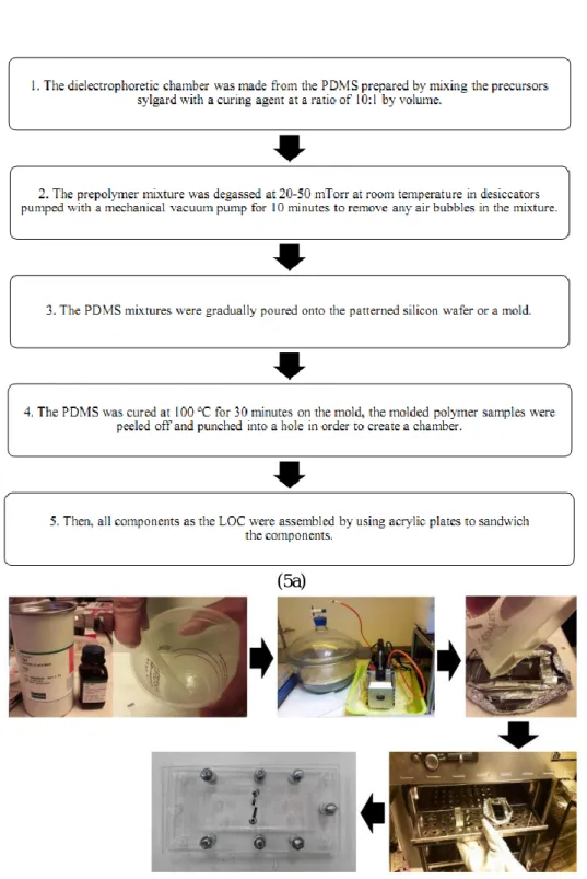
To produce the silicon-wafer casted PDMS LOC, the silicon wafer was patterned by using the negative photo-resist (SU-8 25, MicroChem Co., Newton, MA) technique. The dielectrophoretic chamber was made from the PDMS prepared by mixing the precursors sylgard with a curing agent at a ratio of 10:1 by volume. The prepolymer mixture was degassed at 20-50 mTorr at room temperature in desiccators pumped with a mechanical vacuum pump for 10 minutes to remove any air bubbles in the mixture. The PDMS mixtures were gradually poured onto the patterned silicon wafer or a mold. After the PDMS was cured at 100 oC for 30 minutes on the mold, the molded polymer samples were peeled off and punched into a hole in order to create a chamber. The microelectrodes were inserted into the PDMS electrode chambers manually under the microscope and, then, all components as the LOC were assembled by using acrylic plates to sandwich the components. In each LOC device, there were two inlet reservoirs, two exit reservoirs, channels with 25 micrometers (in z-direction) in height, the main channel with 100 micrometers in width, and two small reservoirs punched on top of the electrodes for the external electrical connections [2, 18-19] as shown on figure 5.
1234567890‘’“”
8th TSME-International Conference on Mechanical Engineering (TSME-ICoME 2017) IOP Publishing IOP Conf. Series: Materials Science and Engineering 297 (2018) 012023 doi:10.1088/1757-899X/297/1/012023
(5a)
(5b)
Figure 5. (5a)The flow diagrams and (5b) the fabrication step for the silicon-wafer casted PDMS LOC.
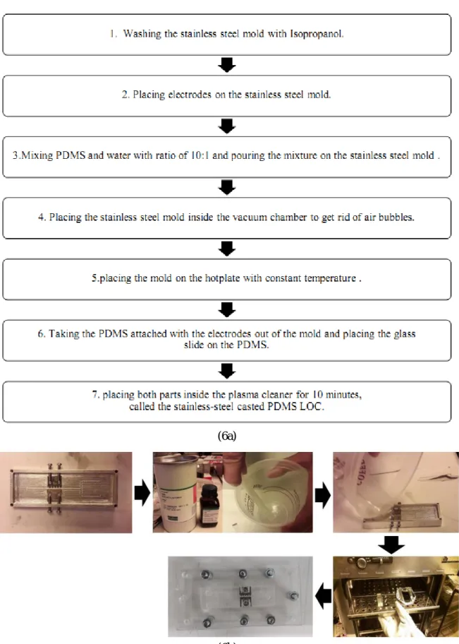
The stainless-steel casted PDMS LOC was casted on the mold imported from Bilkent University, Turkey, there were total of four screws on both sides of the mold; two screws for each side, to hold the electrodes on their positions, control the PDMS flow and to prevent PDMS leakage. The stainless-steel casted PDMS LOC was fabricated at Nanoelectronics and MEMS Laboratory, Thailand National Electronics and Computer Technology Center by following steps; (i) washing the stainless steel mold with Isopropanol, (ii) placing electrodes on the stainless steel mold, (iii) mixing PDMS and water with ratio of 10:1 and pouring the mixture on the stainless steel mold, (iv) placing the stainless steel mold
1234567890‘’“”
8th TSME-International Conference on Mechanical Engineering (TSME-ICoME 2017) IOP Publishing IOP Conf. Series: Materials Science and Engineering 297 (2018) 012023 doi:10.1088/1757-899X/297/1/012023
inside the vacuum chamber to get rid of air bubbles, (v) placing the mold on the hotplate with constant temperature, (vi) taking the PDMS attached with the electrodes out of the mold and placing the glass slide on the PDMS and (vii) placing both parts inside the plasma cleaner for 10 minutes, called the stainless-steel casted PDMS LOC [17] as shown on figure 6.
In this work, there were total of five electrode sets; the first set was for the silicon-wafer casted PDMS LOC and they were prepared by the electroplating technique. The second set was imported with Bilkent University, Turkey, with the stainless steel mold. The third set was produced in Thailand by the electroplating technique. The fourth set was fabricated in Thailand by using the CNC machine. And the fifth set was produced by the double-step electroplating technique. Firstly, the first and third set of electrodes made from nickel by using the traditional electroplating technique as shown on Figure 7. The fourth electrodes were designed and machined by CNC locally in Thailand. There were two electroplating steps in the fifth-electrode fabrication. The first-step electrodes were produced by the traditional electroplating step as processed in the third-electrode fabrication. After that, some parts of the electrodes were taped to allow the nickel to stick on only these parts.Then, the first electrodes were placed on the electrode positions of the silicon-wafer casted LOCs. In the meantime, the second electrodes which were from Bilkent University, the third, fourth and fifth electrodes were placed on the stainless steel mold and the stainless-steel casted LOCs were continued their fabricating processes as mentioned in the previous paragraph.
Finally, the chicken blood was tested inside all LOCs; the silicon-wafer casted LOCs with the first electrodes and the stainless-steel casted LOCs with the second, third, fourth and fifth electrodes. All LOCs were investigated with the chicken blood to find their leakage problems by sandwiching the PDMS and glass-slide parts inside the plasma cleaner.
4. Results and Discussion
The chicken blood was chosen as the biological sample, taken from the chicken by the professional caretaker and prepared by mixing the blood with the ethylenediaminetetraacetic acid (EDTA) as the anticoagulant solution, we already found that the suitable anticoagulant-sample ratio for the chicken sample at 1:1 by volume from our previous work [2, 17].
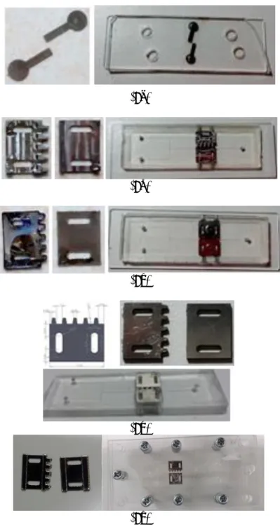
Since the second new electrodes (figure 8(b)) were ready to be used; they were stainless steel plates machined by the micro-CNC machine, we placed these stainless steel electrodes on the mold. Other stainless-steel casted PDMS processes were performed and the stainless-steel casted PDMS was sandwiched with the glass slide inside the plasma cleaner. After we injected the chicken blood sample into the stainless-steel casted LOC reservoir, we found that there was no leakage and we could connect the electrodes with the external electrical circuit to perform electric fields under the 1-voltage electrical-circuit condition. This stainless-steel casted PDMS LOC was proved to be workable and ready to be compared with LOCs with other types of electrodes.
The nickel electrodes for the silicon-wafer LOCs; obtained from the electroplating technique as shown on the left of figure 8(a), were placed on the electrode positions on the PDMS casted from the silicon wafer, the glass slide was placed on top of the first PDMS and electrodes and the silicon-wafer casted LOCs were sandwiched by the plasma cleaner as shown on the right of Figure 8(a). The chicken blood was tested inside the silicon-wafer casted LOCs, we found that leakages surrounding the electrodes and noticed that the electroplated electrodes were thick, the silicon-wafer casted LOCs with the first electrodes were not functioned.
1234567890‘’“”
8th TSME-International Conference on Mechanical Engineering (TSME-ICoME 2017) IOP Publishing IOP Conf. Series: Materials Science and Engineering 297 (2018) 012023 doi:10.1088/1757-899X/297/1/012023
(6a)
(6b)
Figure 6. (6a) The flow diagrams and (6b) the fabrication step for the stainless-steel casted PDMS LOC.
1234567890‘’“”
8th TSME-International Conference on Mechanical Engineering (TSME-ICoME 2017) IOP Publishing IOP Conf. Series: Materials Science and Engineering 297 (2018) 012023 doi:10.1088/1757-899X/297/1/012023
(7a)
1234567890‘’“”
8th TSME-International Conference on Mechanical Engineering (TSME-ICoME 2017) IOP Publishing IOP Conf. Series: Materials Science and Engineering 297 (2018) 012023 doi:10.1088/1757-899X/297/1/012023
(7c)
(7d)
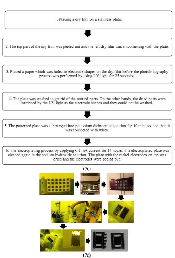
Figure 7. (7a)The flow diagrams and (7b) the fabrication step for the electroplating technique of the first electrodes, (7c)the flow diagrams and (7d) the fabrication step for the electroplating technique of
1234567890‘’“”
8th TSME-International Conference on Mechanical Engineering (TSME-ICoME 2017) IOP Publishing IOP Conf. Series: Materials Science and Engineering 297 (2018) 012023 doi:10.1088/1757-899X/297/1/012023
The electroplating processes were started with placing a dry film on a stainless plate. Then the top part of the dry film was peeled out and the left dry film was smoothen with the plate. We placed a paper which was holed in electrode shapes on the dry film before the photolithography process was performed by using UV light for 25 seconds. After that the plate was washed to get rid of the undried parts. On the other hands, the dried parts were harden by the UV light as the electrode shapes and they could not be washed. The patterned plate was submerged into potassium dichromate solution for 10 minutes and then it was connected with wires. The anode side was also connected with a nickel plate and the cathode side was connected with the stainless steel plate, the nickel dichloride solution was used as the electrolyte solution as shown in figure 6. We induced the electroplating process by applying 0.5 mA current for 17 hours. The electroplated plate was cleaned again in the sodium hydroxide solution. The plate with the nickel electrodes on top was dried and the electrodes were peeled out. We performed these electroplating processes for the first, third and fifth electrodes.
The third nickel electrodes for the stainless-steel LOCs; obtained from the electroplating technique as shown on the left of figure 8(c), were placed on the electrode positions on the stainless steel mold, the PDMS was poured on the mold and the PDMS was casted. We found that, during the PDMS pouring, the electroplated electrodes were floating and moving from their positions because the electrodes were light and not held in their positions. After the glass slide was sandwiched by the plasma cleaner with the PDMS part including the electrodes (The right of figure 8(c)), the chicken blood was tested inside the stainless-steel casted LOCs, we found that there was no leakage but we could not connect the electrodes with the external electrical circuit to perform electric fields because we could not find the certain positions to attached wires. Therefore, the stainless-steel LOCs with the third electrode was unworkable because of the electrode positions. We also discovered that the silicon wafer mold was broken at the channel part, therefore the casted channel did not function as shown in figure 9.
For the fourth electrodes, we designed them as shown on the top left of figure 8(d) and the stainless steel plate were machined according to our design. These machined electrodes were fabricated in Thailand. After the fourth electrodes were delivered, other stainless-steel casted PDMS LOC processes were performed as shown on figure 8(d). The chicken blood sample was investigated in these stainless-steel casted LOCs, we found that there were leakages under the electrode areas even we could connect the electrodes with the external electrical circuit. When we compared the second electrodes with the fourth electrodes, we noticed that there was PDMS attached on patterns on the second electrode backsides and these small PDMS surfaces adjoined well with the glass slide, these small PDMS surfaces played an important role in fabricating the stainless-steel casted LOCs. The backsides of the fourth electrodes were attempted to be milled but the electrodes were broken before the milling process was done. If one could fine a micro-milling machine, this pattern work could be done. Therefore, the last stainless-steel casted LOCs with the fourth electrodes were not workable because of leakage parts underneath the electrodes.
There were two electroplating steps in the fifth-electrode fabrication as shown on figure 8(e). The first-step electrodes were produced by the traditional electroplating step as processed in the third-electrode fabrication. After that, two edge areas along the length of the third-electrodes were taped and the whole electrodes were submerged into the potassium dichromate solution. The tape strips prevented these areas to touch the potassium dichromate solution, when we performed the second electroplating technique, the nickel was electroplated and could adhere on the tape-strip areas while nickel could not stick on made the middle area of the electrodes (the areas with no tape) which was covered by the potassium dichromate solution. The double electroplating technique made a groove on the backside of the fifth electrodes. The fifth electrodes were placed on the stainless mold, when the PDMS was poured on the stainless mold, theses electrodes were in the electrode positions and the PDMS could attach on the back of the fifth electrodes. The PDMS with the double-electroplated electrodes was sandwiched with the glass slides by the plasma cleaner to produce the fifth LOC. The fifth LOC was also experimentally investigated with the chicken blood and found that the chicken blood could flow through the LOC from one end to other ends without any leakages (figure 10).
1234567890‘’“”
8th TSME-International Conference on Mechanical Engineering (TSME-ICoME 2017) IOP Publishing IOP Conf. Series: Materials Science and Engineering 297 (2018) 012023 doi:10.1088/1757-899X/297/1/012023
(8a)
(8b)
(8c)
(8d)
(8e)
Figure 8. (8a)The first, (8b) second, (8c) third, (8d) fourth, and (8e) fifth electrodes.
1234567890‘’“”
8th TSME-International Conference on Mechanical Engineering (TSME-ICoME 2017) IOP Publishing IOP Conf. Series: Materials Science and Engineering 297 (2018) 012023 doi:10.1088/1757-899X/297/1/012023
Figure 9. The broken channel on the first-electrode LOC.
Figure 10. The chicken blood flow inside the workable fifth-electrode LOC. 5. Conclusion
Five new electrodes were fabricated and investigated to apply on two types of LOCs; the silicon-wafer casted PDMS LOC and the stainless-steel casted PDMS LOC. The five sets of the new electrodes consisted of the first sets produced from the nickel electroplating processes for the silicon-wafer casted PDMS LOC, the second sets machined from stainless steel plates at Bilkent University using the micro-CNC machine, the third sets produced from the nickel electroplating processes for the stainless-steel casted PDMS LOC, the fourth sets machined from stainless steel plates in Thailand using the traditional CNC machine the fifth sets also produced from the double-electroplating processes. All five PDMS LOCs were experimentally tested with the chicken blood as biological samples. The silicon-wafer casted PDMS LOC with the first electrodes could not be used with the samples because of its leakages around the electrodes. The stainless-steel casted PDMS LOC with the second electrodes were workable while the stainless-steel casted PDMS LOCs with the third and fourth electrodes were malfunctioned because the third set was misplaced during the PDMS casting process and the fourth electrode surfaces could not adjoin the glass slide surface as close as the second electrode surfaces did. After the problems were indicated, electrode fabrication could be improved. Since we had only one pair of the workable electrodes, the biological sample investigation could not be performed continuously. We have investigated the new technique or the double electroplating process to produce the workable electrodes as in the fifth electrode fabrication. This new technique could help us to produce numerous amount of workable electrodes and we could apply biological samples with these workable LOCs to find health condition-sample flow relationships. These workable LOCs could contribute to animal science with lower cost and less time consumption.
1234567890‘’“”
8th TSME-International Conference on Mechanical Engineering (TSME-ICoME 2017) IOP Publishing IOP Conf. Series: Materials Science and Engineering 297 (2018) 012023 doi:10.1088/1757-899X/297/1/012023
Acknowledgments
The research described in this paper was financially supported by Thermo-Fluid, Material Chemistry and Technology Research Group, Faculty of Science and Engineering and Office of Campus, Kasetsart University, Chalermphrakiat Sakon Nakhon Province Campus, and Kasetsart University Research and Development Institute, Kasetsart University.
References
[1] Li D 2010 Microfluidics Based Microsystems Fundamentals and Applications, Kakaç S, Kosoy B, Li D and Pramuanjaroenkij A eds. (Springer, Netherland) pp 377–397
[2] Pramuanjaroenkij A, Wongpanit, K, Phonong G, Chaiburi B and Kakaç S 2013 Proc. Int. Conf. on
Micro/Nanoscale Heat and Mass Transfer of the ASME (Hong Kong, China) 4
[3] Pohl H A 1978, Dielectrophoretic (Cambridge United Kingdom)
[4] Fu L M, Lee G B, Lin Y H and Yang R J 2004 IEEE/ASME Trans. on Mechatronics 9(2) pp 377–383 [5] Wang X -B, Hughes M P, Huang Y, Becker F F and Gascoyne P R C 1995 Biochimica et Biophysica
Acta 1243 pp 185–194
[6] Yang S, Ündar A, Zahn J D 2006, Lab Chip 6 pp 871–880 [7] Cetin B, Li D 2009 Electrophoresis 30 pp 3124–3133
[8] Cetin B, Kang Y, Wu Z and Li D 2009 Electrophoresis 30 pp 766–772
[9] Cetin, B., Li, D., 2010, Lab-on-a-chip Device for Continuous Particle and Cell Separation Based on Electrical Properties via Alternating Current Dielectrophoresis, Electrophoresis, 31, pp 3035–3043. [10] Kerhoas M K, Sollier E 2013 Lab Chip 13 pp 3323–3346
[11] Kang Y, Cetin B, Wu Z and Li D 2009 Electrochemical Acta 54 pp 1715–1720 [12] Cetin B and Li D 2010 Electrophoresis 32 pp 2410–2427
[13] Jung W C, Heo Y M, Yoon G S, Shin K H, Chang S H, Kim G H and Cho M W 2007Sensors 7 pp 1643–1654
[14] Zeinali S, Cetin B, Oliaei S N B and Karpat Y 2015 Electrophoresis 36 pp 1432–1442
[15] Tripathi S, Kumar Y V B, Agrawal A, Prabhakar A and Joshi S S 2016 Scientific Reports 6 26749 pp 1-15
[16] Ulum M F, Maylina L, Noviana D and Wicaksono D H V 2016 Lab Chip 16 pp 1492–1504 [17] Pramuanjaroenkij A, Jankwan J, Noykuan P, Khammai A, Wongpanit K, Maturos T, Lomas T,
Tuantranont A and Cetin B 2016 Proc. Int. Conf. on Mechanical Engineering of the TSME (Chiang Mai, Thailand)
[18] Pramuanjaroenkij A, Napinij U, Teingtit W, Boonthueng S, Maturos T, Lomas T, Tuantranont A and Kakaç S 2011 Proc. Int. Conf. on Mechanical Engineering of the TSME (Krabi, Thailand) 2 [19] Pramuanjaroenkij A, Thanomsit K, Chaiburi B, Phonong G, Khanaphol A, Phutthasawong W, Maturos T,
Lomas T and Tuantranont A 2012 Proc. Int. Conf.on Mechanical Engineering (Chiang Rai, Thailand)
[20] Bunta J, Thiangpadung J, Sansaradee S 2015 The Comparison Study on Lab-on-a-chip Fabrication from
Different Molds, Senior Project, (Department of Mechanical and Manufacturing Engineering, Faculty
of Science and Engineering, Kasetsart University Chalermphrakiat Sakon Nakhon Province Campus, Thailand)
![Figure 1. Schematic of the simple-microchannel microfluidic device [6].](https://thumb-eu.123doks.com/thumbv2/9libnet/5670955.113554/3.892.147.773.401.609/figure-schematic-of-the-simple-microchannel-microfluidic-device.webp)
![Figure 3. Alternative fabrication techniques of a micro- fluidic device with sidewall electrodes [14]](https://thumb-eu.123doks.com/thumbv2/9libnet/5670955.113554/4.892.123.774.627.729/figure-alternative-fabrication-techniques-fluidic-device-sidewall-electrodes.webp)
![Figure 4. The microfluidic thread-based analytical device [16].](https://thumb-eu.123doks.com/thumbv2/9libnet/5670955.113554/5.892.223.666.170.534/figure-microfluidic-thread-based-analytical-device.webp)