Research Article
NOMA for Multinumerology OFDM Systems
Ayman T. Abusabah
1and Huseyin Arslan
1,21School of Engineering and Natural Sciences, Istanbul Medipol University, 34810 Istanbul, Turkey 2Department of Electrical Engineering, University of South Florida, Tampa, FL 33620, USA
Correspondence should be addressed to Ayman T. Abusabah; [email protected]
Received 23 November 2017; Revised 21 February 2018; Accepted 28 March 2018; Published 9 May 2018 Academic Editor: O˘guz Kucur
Copyright © 2018 Ayman T. Abusabah and Huseyin Arslan. This is an open access article distributed under the Creative Commons Attribution License, which permits unrestricted use, distribution, and reproduction in any medium, provided the original work is properly cited.
Nonorthogonal multiple access (NOMA) is a promising technique which outperforms the traditional multiple access schemes in many aspects. It uses superposition coding (SC) to share the available resources among the users and adopts successive interference cancelation (SIC) for multiuser detection (MUD). Detection is performed in power domain where fairness can be supported through appropriate power allocation. Since power domain NOMA utilizes SC at the transmitter and SIC at the receiver, users cannot achieve equal rates and experience higher interference. In this paper, a novel NOMA scheme is proposed for multinumerology orthogonal frequency division multiplexing system, that is, different subcarrier spacings. The scheme uses the nature of mixed numerology systems to reduce the constraints associated with the MUD operation. This scheme not only enhances the fairness among the users but improves the bit error rate performance as well. Although the proposed scheme is less spectrally efficient than conventional NOMA schemes, it is still more spectrally efficient than orthogonal multiple access schemes.
1. Introduction
Cumulative and incessant demands on new services and applications, in addition to the great expansion in the number of connected devices, have led to a huge data traffic explosion and appearance of different application classes and classifi-cations [1]. Thus, a strong need to boost the expected high data traffic has been recently emerged. Also, since it became obvious that next generation has to support high data rates, applications industry and academia agreed on the necessity of new and flexible radio access technologies (RATs) [2].
Multiple access (MA) techniques play a major role in the overall communication process. Since the first generation up until the fourth generation, MA techniques were distributing the users over the available resources orthogonally. For instance, time division multiple access, frequency division multiple access, code division multiple access, and orthogonal frequency division multiple access (OFDMA) are considered as orthogonal multiple access (OMA) techniques. Eventually, researchers have moved away from utilizing the resources in an orthogonal way to a nonorthogonal one, which they call nonorthogonal multiple access (NOMA) [3].
Power domain NOMA adopts multiplexing multiple users through sharing the same resources at the transmitter (TX). Furthermore, it uses successive interference cancela-tion (SIC) as a multiuser deteccancela-tion technique to separate the users through power differences at the receiver (RX) side. NOMA is considered as a promising multiple access technique for the fifth-generation wireless networks due to massive connectivity, low latency, and high spectral efficiency (SE) [4].
It is shown that, by adopting NOMA with orthogonal frequency division multiplexing- (OFDM-) based method as RAT, multiple users can be allocated on a subcarrier at the same time. However, the cochannel interference (CCI) per subcarrier increases as more users are multiplexed on the same subcarrier, which degrades the system performance [5]. In [6], the authors have studied users’ pairing; then they concluded that NOMA outperforms OMA especially with users whose channel conditions are more distinctive, which is practically difficult to occur.
Power control/allocation has been studied in many works [7]. To guarantee the fairness among NOMA users, more power is required for users with poor channel conditions
user 1 user 2 user 3 FFT N 1 0.8 0.6 0.4 0.2 0 Normalized Bandwidth Po w er 2 0 −2 −4
(a) Carrier representation for conventional NOMA at the RX end
FFT 2N user 1 user 2 user 3 Normalized Bandwidth 1 0.8 0.6 0.4 0.2 0 Po w er 2 0 −2 −4
(b) Carrier representation for proposed NOMA at the RX end
CP + user 3 user 2 user 1 Time F req uenc y T BNIN
(c) Time representation for conventional NOMA at the TX end
CP + user 1 user 3 user 2 Time F req uenc y 2T T BNIN
(d) Time representation for proposed NOMA at the TX end
Figure 1: Signals superposition in time and frequency domains.
and less power for users with better channel conditions [8]. However, if the users have similar channel conditions, OMA can guarantee better fairness and conventional power domain NOMA cannot strictly guarantee the users’ quality of service (QoS) targets [9], which could be critical for some scenarios with strict fairness constraints.
In this work, we propose an OFDM based NOMA scheme. The scheme utilizes the numerology concept to reduce the constraints associated with the conventional NOMA schemes. Simply, the users utilize different subcarrier spacings, wide subcarriers, and narrow subcarriers. A three-user scenario is considered in this paper. In the conventional scheme, the three users are supposed to share the same subcarriers as shown in Figure 1(a), while in the proposed scheme one user is assigned narrower and less frequently spaced subcarriers as illustrated in Figure 1(b).
The subcarriers configuration of the proposed scheme is characterized by the fact that the wide subcarrier users are fully overlapped within the same wide subcarriers and make a zero crossing at the peaks of the other wide subcarriers. Furthermore, the narrow subcarriers do not impose any interference at the peaks of wide subcarriers, that is, by avoiding the transmission on the half of narrow subcarriers. As a result, the wide subcarriers are not affected by any external interference. On the other hand, an interference is imposed by the tails of the wide subcarriers on the peaks of the narrow subcarriers.
Even though the narrow subcarriers share the bandwidth with the wide subcarriers, the detection, of wide subcarrier users, is independent of narrow subcarrier users; therefore, SIC can be used to detect the wide subcarrier users based on their power differences. On the other hand, the narrow subcarriers are detected once the interference imposed by wide subcarriers is eliminated.
By assigning one of the users narrower subcarriers, we reduce the amount of CCI imposed on the wide subcarrier users. Furthermore, the interference imposed on the narrow subcarrier user can be easily canceled by eliminating the wide subcarrier signals, which enhances the bit error rate (BER) performance for each user.
The narrow subcarrier user has an extra degree of free-dom (DOF) as its power level is independent of the detection process; that is, it is not restricted to the wide subcarrier users and does not affect their detection process. In other words, the SIC process does not depend on the power level of the narrow subcarriers which grants more flexibility for power assigning. Based on that, the proposed scheme has the advantage of providing a fairer rate allocation to the users compared with the conventional scheme especially when the channel conditions of the users are similar.
The subcarriers configuration of Figure 1(b) can be simply accomplished by composing the symbols of wide subcarrier users synchronously in the time domain, that is, each with a length of one OFDM symbol slot. Then, the extended
symbol, that is, narrow subcarrier user, is added. However, a novel structure is adopted for the transmission. As shown in Figure 1(d), the OFDM symbol slots of wide subcarrier users are orthogonally constructed and then the extended symbol of narrow subcarrier user is added. In this case, the wide subcarrier users are composed at the RX end and the proposed subcarrier configuration is obtained. In both transmission structures, the resulting signal consists of two OFDM symbol slots and the utilized resources are the same.
To achieve this purpose, a fast Fourier transform (FFT) operation, with the length of two OFDM symbol slots, is performed at the RX end. By doing this, the wide subcarrier users are multiplexed at the RX end. Extending the length of FFT window at the RX end allows us to equalize the channel using one cyclic prefix (CP) [10], which is a good solution to increase the SE even with an absolute OFDMA system.
The rest of the paper is organized as follows: Section 2 presents the signal configuration of the proposed scheme. Problem description, features, and potentials for our tech-nique are provided in Section 3. The system model for con-ventional multicarrier NOMA scheme is given in Section 4. The design analysis is provided in Section 5. Simulation results are shown in Section 6. Finally, Section 7 concludes our paper.
2. Signal Configuration
The frequency and time representations, for conventional NOMA scheme, are shown in Figures 1(a) and 1(c), respec-tively. Three different power signals are multiplexed utilizing the same resources, where each signal constitutes one OFDM symbol slot; then a CP is appended. Therefore, the SE is expected to be doubled 3 times compared with OFDMA system without considering the CP redundancy.
On the other hand, in proposed NOMA, one of the users (user-2) is assigned narrower and less frequent subcarriers as illustrated in Figure 1(b), which simply multiplies the symbol duration by two as depicted in Figure 1(d). Since the new structure uses only𝑇 seconds out of a possible 2𝑇, the SE, defined as bps/Hz, is halved for the wide subcarrier users. Meanwhile, as the total energy budget is the same, the power used by wide subcarrier users is twice as before. As the SE increases logarithmically with power, this increase does not compensate for the .5 loss in the SE; thus, the overall SE improvement over OFDMA is greater than 1 but strictly less than 1.5.
As mentioned earlier, the subcarriers’ configuration in Figure 1(b) can be obtained if both symbols of user 1 and user 3 share the first half of user 2 symbol. However, in Figure 1(d), user 1 and user 3 are constructed orthogonally at the TX. In this case, the subcarriers’ configuration of the proposed scheme is accomplished at the RX end where the wide subcarrier users (user 1 and user 3) are multiplexed by adopting an extended FFT operation.
In Figure 1(d), user 3 symbol is multiplexed with the first half of user 2 symbol and user 1 does the same with the second half. This can be seen from Figure 1(b) as well, where user 2 has a contribution from user 1 and user 3 at the peaks. Note that, user 1 and user 3 are orthogonal with respect to each
other at the TX side. However, processing them together at the RX side, that is, by using an extended FFT window, makes them overlapping and therefore nonorthogonal. As the basic NOMA concept based on multiplexing the users at the TX utilizing the same resources, the proposed scheme can be considered as a half NOMA.
The key advantage of using larger FFT window size at RX is the capability of equalizing the channel using one CP for the whole OFDM symbols and thus increasing the SE. This property can be even used for a pure OFDMA system. For example, in the absence of user 2 in Figure 1(d), the system becomes an OFDMA system. Then, if FFT operation, with the length of two OFDM symbols, is performed at the RX, the transmitted symbols are composed and one CP can be used for equalization rather than two. In our case, the composed signals are detected in power domain and user 2 is able to share the other users’ resources without introducing any extra interference.
Note that user 2 signal (narrow subcarriers) makes a zero crossing with the other signals (wide subcarriers) at the peaks. This can be clearly concluded from frequency domain repre-sentation. The same result is not obvious from time domain representation. In Section 5, it is proven mathematically that, by adopting an extended FFT window size at the RX end, the wide subcarrier users are multiplexed although they are assigned different OFDM symbol slots at the TX and the narrow subcarrier users do not affect their detection process.
3. Problem Description
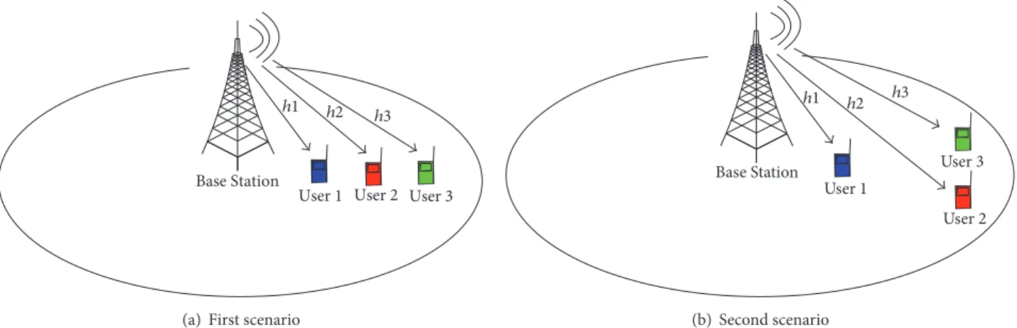
To describe the features of our proposed scheme, two scenar-ios are considered. The first scenario appears in Figure 2(a) where three downlink users have distinctive channel condi-tions|ℎ|, while the second scenario appears in Figure 2(b), where two users have similar channel conditions; that is, two users are at the cell edge and one user is close to the base station (BS).
In the case of the users whose channel conditions are similar, like the second scenario, either we assign similar power allocation (PA) to achieve the fairness and, therefore, SIC cannot work properly due to its inherent nature which depends on power differences for separation, or we assign different PA which leads explicitly to unfairness distribution.
3.1. Conventional NOMA (CN). If users have distinctive|ℎ|
as represented in Figure 2(a), under perfect channel state information assumption at the BS, achieving the fairness can be ensured through a proper PA. Furthermore, degradation in the performance due to the number of assigned users is expected. For instance, user 3 signal has to be detected with the presence of user 2 and user 1 signals by considering them as a noise, which degrades the BER performance.
In the second scenario, user 2 and user 3 experience the same channel effect. Therefore, if the fairness is a system requirement, both users have to be assigned similar PA. However, the natural work of SIC depends on the power differences to facilitate the separation process. Thus, with similar PA, the internal interference cannot be avoided and the performance can be extremely degraded.
Base Station
h1 h2 h3
User 1 User 2 User 3
(a) First scenario
Base Station h1 h2 h3 User 1 User 2 User 3 (b) Second scenario
Figure 2: Two different user distribution scenarios: (a)|ℎ1,𝑤| > |ℎ2,𝑤| > |ℎ3,𝑤| and (b) |ℎ1,𝑤| > (|ℎ2,𝑤| = |ℎ3,𝑤|).
3.2. Proposed NOMA (PN). According to the first scenario,
by assigning user 2 narrow subcarriers, we reduce the interference imposed on user 1 and user 3 signals. Thus, SIC process becomes easier since it has to differentiate two signals rather than three based on their power differences. Actually, the narrow subcarrier user is selected so that the other users, that is, wide subcarrier users, obtain more distinctive channel conditions. Besides, the PA of user 2 is determined independently which grants more flexibility for the system design.
This becomes very beneficial for the second scenario where achieving the fairness is an issue. As mentioned before, user 2 and user 3 cannot be paired as they have similar channel conditions. Nevertheless, if user 2 is assigned narrow subcarriers, user 3 and user 1 can be paired and a proper PA is determined. Naturally, the PA of user 2 is not restricted by the other users.
4. Conventional NOMA System Model
Conventional multicarrier downlink NOMA system is for-mulated by considering𝐼 downlink users around a BS as shown in Figure 2. Users are distributed randomly and served by one BS and the total bandwidth𝐵totconsists of𝑁scnumber of orthogonal subcarriers in frequency domain. Transceivers are supposed to be equipped with one antenna, and𝐼 users share𝑁scOFDM subcarriers through superposition coding.
The BS assigns different power levels depending on users’ conditions in order to achieve the fairness in the system and provide the capability of detection at the RX side using SIC. So, high power is assigned to the poor users, that is, far users, and low power to ones whose channel conditions are good. In other words, NOMA exploits the heterogeneity of users’ distribution and then allows the separation in the power domain [11].
The BS is transmitting the signal𝑥𝑖,𝑤to the𝑖th user (𝑖 = {1, 2, . . . , 𝐼}) on the 𝑤th subcarrier (𝑤 = {1, 2, . . . , 𝑁sc}) with
transmission power𝑃𝑖,𝑤, and, then, the received signal by user 𝑖 on subcarrier 𝑤 is given by [12] as follows:
𝑦𝑖,𝑤= ℎ𝑖,𝑤∑𝐼
𝑢=1√𝑃𝑢,𝑤
𝑥𝑢,𝑤+ 𝑧𝑖,𝑤, (1)
where 𝑧𝑖,𝑤 represents the additive white Gaussian noise (AWGN) for the𝑖th user on subcarrier 𝑤 with a zero mean and𝜎𝑖,𝑤2 variance, that is,𝑧𝑖,𝑤 ∼ N(0, 𝜎2𝑖,𝑤), and ℎ𝑖,𝑤denotes the channel gain between the BS and the received user at the𝑤th subcarrier including both effects of large and small scale fading. Path loss and shadowing are considered as small fading effects. On the other hand, block Rayleigh is adopted for large-scale fading.
Without loss of generality, the channels are sorted as |ℎ1,𝑤|2> |ℎ
2,𝑤|2> ⋅ ⋅ ⋅ > |ℎ𝑖,𝑤|2> ⋅ ⋅ ⋅ > |ℎ𝐼,𝑤|2> 0. For a given
subcarrier, a user who enjoys a better downlink channel quality can decode and remove the CCI from a user who has a worse downlink channel quality by employing SIC [5]; thus, user 𝑖 enjoys a better channel quality than user (𝑖 + 1). At the𝑖th user, if SIC is carried out perfectly, then achieving the fairness follows Shannon’s equation [13], where the achievable rate of the𝑖th user for 𝐵totHz system bandwidth at the RX side is given by 𝑅𝑖= 𝐵sc 𝑁sc ∑ 𝑤=1 log2(1 + SINR𝑖,𝑤) , SINR𝑖,𝑤= ( 𝑃𝑖,𝑤ℎ𝑖,𝑤 2 ℎ𝑖,𝑤2∑𝑖−1𝑢=1𝑃𝑢,𝑤+ 𝜎𝑖,𝑤2 ) , (2)
where SINR𝑖,𝑤 is the instantaneous signal-to-interference-plus-noise ratio by user𝑖 on the 𝑤th subcarrier and 𝐵sc = 𝐵tot/𝑁scis the subcarrier bandwidth. Note that if the strongest
user, that is, user 1, decodes and cancels all other users’ signals successively, then the achievable data rate is given by𝑅1 = 𝐵sc∑sc𝑤=1log2(1 + 𝑃1,𝑤|ℎ1,𝑤|2/𝜎21,𝑤).
5. Signal Representation and Design Analysis
This section considers the design analysis of our proposed scheme. The mathematical model of the proposed scheme is established. The time domain signal in Figure 1(d) is formulated. Then, it is shown that, by adopting FFT operation with a length of two OFDM symbols at the RX side, the wide subcarrier users are composed although they are orthogo-nally transmitted.
Generation of wide subcarrier signals can be done using an inverse fast Fourier transform (IFFT) process with a length of𝑁 samples. On the other hand, narrow subcarrier signals can be also generated using IFFT process with a length of𝑀 = 𝑄𝑁 samples, where 𝑄 is the ratio between the two different subcarrier spacings or the two different symbol lengths.
According to Figure 1(b), user 1 and user 3 signals are generated using IFFT with𝑁 points, while user 2 signal is generated utilizing IFFT with𝑀 = 2𝑁 points. It is worth mentioning that, to avoid direct interference with wide sub-carriers, we do not use all of the narrow subcarriers for trans-mission. In our example, narrow-odd subcarriers are used for user 2 data transmission while narrow-even ones are filled with zeros using subcarrier mapping (SM).
An OFDM transmission symbol, of wide subcarrier user, is given by the𝑁 point complex modulation sequence
𝑥𝑤𝑎(𝑛) = √𝑃𝛼𝑎IFFT(𝑋𝑤𝑎) = 1 𝑁√𝑃𝛼𝑎 𝑁−1 ∑ 𝑘=0 𝑋𝑤𝑎(𝑘) ⋅ 𝑒𝑗2𝜋𝑛𝑘/𝑁, for𝑛 = 0, 1, . . . , 𝑁 − 1, 𝑎 = 0, 1, . . . , 𝐴, (3)
where𝑋𝑤𝑎(𝑘) is the complex modulated symbol of 𝑎th user on𝑘th subcarrier; that is, 𝐴 is the number of wide subcarrier users, 𝛼𝑎 is the assigned PA factor to the 𝑎th user, and ∑𝐴𝑎=1𝑃𝛼𝑎 is the amount of power that is specified for wide subcarrier users.
In a similar way, the OFDM transmission symbol, for narrow subcarrier user, is given by the 𝑀 point complex modulation sequence 𝑥nr𝑏(𝑚) = √𝑃𝛽𝑏IFFT(̂𝑋𝑏) = 1 𝑀√𝑃𝛽𝑏 𝑀−1 ∑ 𝑙=0 ̂ 𝑋𝑏(𝑙) ⋅ 𝑒𝑗2𝜋𝑚𝑙/𝑀, for𝑚 = 0, 1, . . . , 𝑀 − 1, 𝑏 = 0, 1, . . . , 𝐵. (4) ̂ 𝑋𝑏(𝑙) ={{ { 𝑋nr𝑏( 𝑙 − 1 𝑄 ) , 𝑙 = 𝑄𝑘 + 1, (𝑙 = 1, 3, . . . , 𝑀 − 1) 0, o.w., (5)
where ̂𝑋𝑏(𝑙) is the complex modulated symbol of 𝑏th user on 𝑙th subcarrier after SM; that is, 𝐵 is the number of narrow subcarrier users,𝛽𝑏is the assigned PA factor to the𝑏th user, ∑𝐵𝑏=1𝑃𝛽𝑏is the amount of power that is specified for narrow
subcarrier users,𝐼 = 𝐴 + 𝐵 is the total number of users, and the maximum assigned power from the BS to all users is𝑃 = ∑𝐴𝑎=1𝑃𝛼𝑎+∑𝐵𝑏=1𝑃𝛽𝑏; that is,𝐵 = 0 represents the conventional NOMA scheme case.
The wide subcarrier signals (𝑥𝑤) are assigned different time slots to form one block𝑥𝑥𝑤with a length of𝑀 samples. Thereafter, the narrow subcarrier signals (𝑥nr) are added
together forming another block𝑥𝑥nrwhich is already with a length of𝑀 samples. Finally, the resultant blocks are added synchronously to produce one block 𝑠 with a length of 𝑀 samples for the transmission; this process can be expressed as follows:
𝑠 = 𝑥𝑥𝑤+ 𝑥𝑥nr,
𝑥𝑥𝑤= [𝑥𝑤1, . . . , 𝑥𝑤𝐴]𝑀=𝐴𝑁, 𝑥𝑥nr=∑𝐵
𝑏=1
𝑥𝑛𝑟𝑏. (6) According to the proposed scheme in Figure 1,𝐴 = 2, 𝐵 = 1, 𝑀 = 2𝑁, and 𝑄 = 2. So (6) can be written as follows:
𝑥𝑥𝑤= [𝑥𝑤1, 𝑥𝑤2]2𝑁,
𝑥𝑥nr= [𝑥nr1]𝑀=2𝑁. (7) By assuming𝑚 = 𝑛 + 𝑞𝑁, (4) can be expressed as follows:
𝑥nr(𝑛 + 𝑞𝑁) = 1 𝑀 𝑁−1 ∑ 𝑘=0√𝑃𝛽1 𝑋nr(𝑄𝑘+ 1) ⋅ 𝑒𝑗2𝜋(𝑛+𝑞𝑁)(𝑄𝑘+1)/𝑀, for𝑛 = 0, 1, . . . , 𝑁 − 1, 𝑞 = 0, 1, . . . , 𝑄 − 1. (8)
Since𝑄 = 2, the first half and second half of 𝑥nrsignal can be represented by setting𝑞 to 0 and 1, respectively:
𝑥nr(𝑛) = 𝑀1 𝑁−1∑ 𝑘=0√𝑃𝛽1 𝑋nr(𝑄𝑘+ 1) ⋅ 𝑒𝑗2𝜋𝑛(𝑄𝑘+1)/𝑀, for 𝑞 = 0, 𝑥nr(𝑛 + 𝑁) = 𝑀1 𝑁−1∑ 𝑘=0√𝑃𝛽1 𝑋nr(𝑄𝑘+ 1) ⋅ 𝑒𝑗2𝜋(𝑛+𝑁)(𝑄𝑘+1)/𝑀, for 𝑞 = 1, 𝑥nr(𝑛 + 𝑁) = −𝑥nr(𝑛) . (9)
Thus, the second half of the signal𝑥nris just a reversal copy of the first half because of odd subcarriers usage. From (9), the transmitted signal𝑠 in (6) can be expressed as follows:
𝑠 (𝑟) ={{ {
𝑥𝑤1(𝑟) + 𝑥nr1(𝑟) , 0 < 𝑟 < 𝑁 − 1
𝑥𝑤2(𝑟) − 𝑥nr1(𝑟) , 𝑁 < 𝑟 < 2𝑁 − 1, (10) where𝑟 represents the composed signal sample index (𝑟 = {0, 1, . . . , 𝑀 − 1}).
After composing the signals, to avoid intersymbol inter-ference and enable frequency domain equalization (FDE) at the RX, a copy from the resultant tail is appended as a CP where its duration has to be larger than the maximum excess delay of the channel.
At the RX end and after removing the CP, FFT operation, with a length of𝑀 = 2𝑁 points, is performed as follows:
𝑆 (V) =𝑀−1∑
𝑟=0𝑠 (𝑟) ⋅ 𝑒
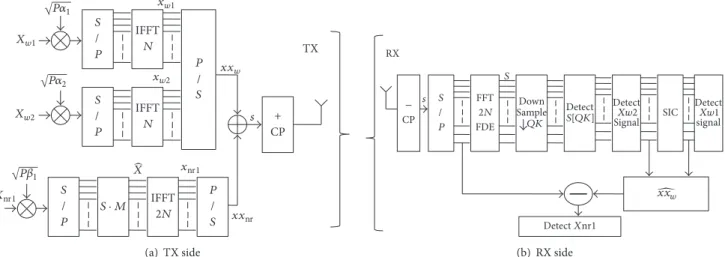
S / P IFFT N P / S IFFT 2N P / S TX s S / P IFFT N S / P Xw1 Xw2 Xnr1 √P1 √P1 √P2 CP + S · M X xw1 xw2 xnr1 xxw xxnr (a) TX side − CP S / P FFT 2N FDE Detect S[QK] Detect Xw2 Signal SIC s Detect Xw1 signal S Detect Xnr1 RX Down Sample QK xxw (b) RX side
Figure 3: Transceiver design for proposed NOMA scheme adopting three downlink users.
where𝑆 are the received complex symbols after FFT opera-tion. Afterwards, FDE takes the responsibility to get rid of channel’s sparsity where single tap equalization is available. To compute the output on the even and odd subcarriers, we assume thatV = 𝑄𝑘 + 𝑞, and, then, (11) can be represented as
𝑆 (𝑄𝑘 + 𝑞) =𝑁−1∑ 𝑟=0 (𝑥𝑤1(𝑟) + 𝑥nr1(𝑟)) ⋅ 𝑒−𝑗2𝜋𝑟(𝑄𝑘+𝑞)/𝑄𝑁 +2𝑁−1∑ 𝑟=𝑁 (𝑥𝑤2(𝑟) − 𝑥nr1(𝑟)) ⋅ 𝑒−𝑗2𝜋𝑟(𝑄𝑘+𝑞)/𝑄𝑁. (12)
By setting𝑞 = 0 and assuming 𝑧 = 𝑟 − 𝑁 for the second part of (12), then, the output on even subcarriers is proven to be
𝑆 (𝑄𝑘) = √𝑃𝛼1𝑋𝑤1(𝑘) + √𝑃𝛼2𝑋𝑤2(𝑘) . (13)
Explicitly, (13) proves that although𝑋𝑤1 and𝑋𝑤2signals are constructed orthogonally at the TX, they are multiplexed by utilizing larger FFT window at the RX side. In addition, (13) ensures the absence of narrow subcarriers contribution to wide subcarriers; thereafter, SIC separates the wide subcarrier signals based on power differences.
User 1 and user 3 signals are constructed again; then, the reconstructed signal𝑥𝑥̂𝑤is subtracted from the received signal𝑠 with a view to detect user 2 signal. Transceiver block diagram is given in Figure 3 for the proposed NOMA scheme.
6. Performance Evaluation
In this section, we evaluate the performance of proposed NOMA scheme through simulation. System parameters are presented in Table 1.
6.1. BER. The BER performance is supposed to be enhanced
by performing proposed NOMA due to many reasons. Mainly, wide subcarrier users experience lower number
Table 1: Simulation parameters.
Parameter name Value
Number of wide subcarriers (𝑁) 64
Number of narrow subcarriers (𝑀) 128
Modulation type QPSK
Total system bandwidth 5 MHz
Total power 10 dBm
The first scenario|ℎ𝑖,𝑤|2/𝜎2𝑖,𝑤 20 dB, 17 dB, 0 dB for𝑖 = 1, 2, 3
The second scenario|ℎ𝑖,𝑤|2/𝜎𝑖,𝑤2 20 dB, 0 dB, 0 dB, for𝑖 = 1, 2, 3
of interferer users. Moreover, the interference imposed on narrow subcarrier user can be eliminated by detecting and canceling wide subcarrier users and utilizing the unused narrow subcarriers. Furthermore, the narrow subcarrier user can enjoy any power level. Thus, the BER performance is enhanced significantly. Note that the SINR values are considered at the RX side after FFT process.
The SINR𝑐𝑖,𝑤 values utilizing conventional NOMA scheme for user 1, user 2, and user 3 on subcarrier𝑤, with successful decoding and no error propagation assumption, are given by SINR𝑐1,𝑤= (𝛼1𝑃 ℎ1,𝑤 2 𝜎2 1,𝑤 ) , SINR𝑐2,𝑤= ( 𝛼2𝑃 ℎ2,𝑤 2 ℎ2,𝑤2𝛼1𝑃 + 𝜎22,𝑤 ) , SINR𝑐3,𝑤= ( 𝛼3𝑃 ℎ3,𝑤 2 ℎ3,𝑤2(𝛼1+ 𝛼2) 𝑃 + 𝜎3,𝑤2 ) , (14)
while SINR𝑝𝑖,𝑤values utilizing proposed NOMA scheme are expressed as follows:
SINR𝑝1,𝑤= (𝛼1𝑃 ℎ1,𝑤
2
𝜎2
SINR𝑝2,𝑤= (𝛽1𝑃 ℎ2,𝑤 2 𝜎2 2,𝑤 ) , SINR𝑝3,𝑤= ( 𝛼2𝑃 ℎ3,𝑤 2 ℎ3,𝑤2𝛼1𝑃 + 𝜎3,𝑤2 ) . (15) Using the same PA for both schemes, we can notice from (14) and (15) that the first user experiences the same SINR values, while a big enhancement, in SINR values, is noticeable for the second and third user utilizing proposed NOMA.
6.2. Fairness Factor (𝐹). To evaluate the fairness level for
conventional and proposed NOMA we define the factor𝐹 as in [14], where𝐹 measures the equality of users’ rate 𝑅 for a given system and it is given by
𝐹 = (∑
𝐼
𝑖=1𝑅𝑖)2
𝐼 ∑𝐼𝑖=1(𝑅𝑖)2. (16) For instance, if all users get the same amount of𝑅, then the value𝐹 will be close to 1.
The goal of PA mechanism is to maximize the sum capacity under a fairness constraint for NOMA systems. The optimization problem is formulated as
max 𝛼𝑎,𝛽𝑏 𝐵sc 𝐼 ∑ 𝑖=1 𝑁sc ∑ 𝑤=1 log2(1 + SINR𝑖,𝑤) s.t: ∑𝐼 𝑖=1 𝑁sc ∑ 𝑤=1𝑃𝑖,𝑤≤ 𝑃 𝑃𝑖,𝑤≥ 0, ∀𝑖, ∀𝑤 𝐹 = 𝐹, (17)
where𝐹 is the target fairness index in the network. The PA coefficients (𝛼𝑎, 𝛽𝑏) are obtained through exhaustive search using algorithm 1 in [15].
According to the first scenario, the optimal PA coefficients utilizing conventional NOMA and proposed NOMA schemes are equal to[𝛼1𝛼2𝛼3] = [0.01 0.15 0.84] and [𝛼1𝛽2𝛼2] = [0.08 0.36 0.56], respectively. On the other hand, based on the second scenario, the optimal PA coefficients utiliz-ing conventional NOMA and proposed NOMA are found to be [𝛼1𝛼2𝛼3] = [0.02 0.39 0.59] and [𝛼1𝛽2𝛼2] = [0.13 0.34 0.53], respectively.
Based on the obtained optimal PA coefficients, the BER performance is evaluated. The normalized channel gains (|ℎ𝑖,𝑤|2/𝜎2
𝑖,𝑤) are set as in Table 1 and the fairness index𝐹 is
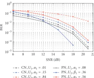
assumed to be 0.7. The individual BER for the first and the second scenarios are shown in Figures 4 and 5, respectively. Using the optimal PAs obtained for the second scenario, the fairness level, of conventional and proposed NOMA schemes, is evaluated as depicted in Figure 6. The results show clear dominance of proposed NOMA over conventional NOMA in terms of BER and fairness level.
SNR (dB) 22 20 18 16 14 12 10 8 6 10−5 10−4 10−3 10−2 10−1 100 BER CN, U1, 1= .01 CN, U2, 2= .15 CN, U3, 3= .84 PN, U1, 1= .08 PN, U2, 1= .36 PN, U3, 2= .56
Figure 4: BER performance utilizing the optimum PA for
conven-tional and proposed NOMA in the first scenario,𝐹 = 0.7.
SNR (dB) 22 20 18 16 14 12 10 8 6 10−5 10−4 10−3 10−2 10−1 100 BER CN, U1, 1= .02 CN, U2, 2= .39 CN, U3, 3= .59 PN, U1, 1= .13 PN, U2, 1= .34 PN, U3, 2= .53
Figure 5: BER performance utilizing the optimum PA for
conven-tional and proposed NOMA in the second scenario,𝐹 = 0.7.
0. (1= .13, 1= .34, 2= .53) #. (1= .02, 2 = .39, 3= .59) 0. (1= .02, 2 = .39, 3= .59) #. (1= .13, 1= .34, 2= .53) 0.45 0.5 0.55 0.6 0.65 0.7 0.75 0.8 0.85 Fa ir n es s Fa ct o r 2 3 4 5 6 7 8 9 10 1 SNR (dB)
Figure 6: Fairness level of conventional and proposed NOMA utilizing the optimum PA for the second scenario.
#., (U1, 1= .01) , (U2, 2= .15) , (U3, 3= .84) 0., (U1, 1= .08) , (U2, 1= .36) , (U3, 2= .56) OMA,P1= P2= P3 5 10 15 20 0 SNR (dB) 2 3 4 5 6 7 SE (b ps/H z)
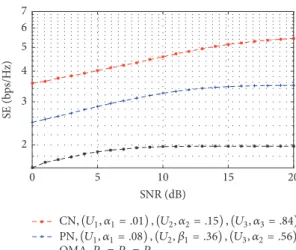
Figure 7: Average spectral efficiency adopting conventional NOMA, proposed NOMA, and OMA using the optimum PA for the first scenario.
6.3. Spectral Efficiency (SE). The spectral efficiency 𝜂𝑖 =
𝑅𝑖/𝐵tot represents the amount of the carried data over the available resources. In [16], it is proven that the conventional NOMA schemes can offer a better SE than OMA. In con-ventional NOMA, the SE is expected to improve dramatically since three users utilize the available resources, that is, time and frequency units. Unfortunately, this comes at a price of unguaranteed QoS and loss of fairness. On the other hand, although proposed NOMA offers less SE than conventional NOMA due to additional time unit usage, that is, two time slots, it still provides superior SE compared with OMA. In particular, the superior SE in proposed NOMA arises from the capability of the narrow subcarrier user to share the available resources in addition to CP reduction between OFDM symbols.
The first scenario in Figure 2(a) is considered in the evaluation of the average SE for OMA, conventional NOMA, and proposed NOMA. For OMA, the bandwidth𝐵totand the total power𝑃 are split equally between the assigned users. The SE performance is illustrated in Figure 7.
It is obvious from Figure 7 that the SE of proposed NOMA is decreased compared to conventional NOMA; however, it is still more spectrally efficient than OMA.
7. Conclusion
In this work, some of the NOMA-OFDM system based problems have been addressed by employing numerology concept cleverly. More DOF are given to one of the composed users by assigning narrower subcarriers. Based on this DOF, the constraints associated with the conventional NOMA schemes have been reduced and the BER performance has been improved too. Furthermore, the proposed method has proven its superiority in affording a fairer rate allocation to the users compared to conventional method.
A new methodology of multiplexing the users, in power domain, has been implemented by adopting a larger FFT window at the RX end. As a result, the guard durations
between OFDM symbols became unnecessary. Thus, our proposed scheme is more spectrally efficient than OMA schemes.
Conflicts of Interest
The authors declare that there are no conflicts of interest regarding the publication of this paper.
Acknowledgments
The authors thank Khawar Hussain, Research Assistant, for assistance and comments that greatly improved the manuscript.
References
[1] U. L. Rohde, A. K. Poddar, I. Eisele, and E. Rubiola, “Next generation 5G radio communication NW,” in Proceedings of
the 2017 Joint Conference of the European Frequency and Time Forum and IEEE International Frequency Control Symposium ((EFTF/IFC), pp. 113–116, Besanc¸on, France, July 2017.
[2] J. G. Andrews, S. Buzzi, and W. Choi, “What will 5G be?” IEEE
Journal on Selected Areas in Communications, vol. 32, no. 6, pp.
1065–1082, 2014.
[3] L. Dai, B. Wang, Y. Yuan, S. Han, C. I, and Z. Wang, “Non-orthogonal multiple access for 5G: solutions, challenges, oppor-tunities, and future research trends,” IEEE Communications
Magazine, vol. 53, no. 9, pp. 74–81, 2015.
[4] Z. Ding, Z. Zhao, M. Peng, and H. V. Poor, “On the Spectral Efficiency and Security Enhancements of NOMA Assisted Multicast-Unicast Streaming,” IEEE Transactions on
Communi-cations, vol. 65, no. 7, pp. 3151–3163, 2017.
[5] Y. Sun, D. W. K. Ng, Z. Ding, and R. Schober, “Optimal joint power and subcarrier allocation for full-duplex multicarrier non-orthogonal multiple access systems,” IEEE Transactions on
Communications, vol. 65, no. 3, pp. 1177–1191, 2017.
[6] Z. Ding, P. Fan, and H. V. Poor, “Impact of User Pairing on 5G Nonorthogonal Multiple-Access Downlink Transmissions,”
IEEE Transactions on Vehicular Technology, vol. 65, no. 8, pp.
6010–6023, 2016.
[7] S. Timotheou and I. Krikidis, “Fairness for Non-Orthogonal Multiple Access in 5G Systems,” IEEE Signal Processing Letters, vol. 22, no. 10, pp. 1647–1651, 2015.
[8] S. M. R. Islam, N. Avazov, O. A. Dobre, and K.-S. Kwak, “Power-Domain Non-Orthogonal Multiple Access (NOMA) in 5G Systems: Potentials and Challenges,” IEEE Communications
Surveys & Tutorials, vol. 19, no. 2, pp. 721–742, 2017.
[9] Z. DIng, X. Lei, G. K. Karagiannidis, R. Schober, J. Yuan, and V. K. Bhargava, “A Survey on Non-Orthogonal Multiple Access for 5G Networks: Research Challenges and Future Trends,” IEEE
Journal on Selected Areas in Communications, vol. 35, no. 10, pp.
2181–2195, 2017.
[10] J.-Y. Chouinard, X. Wang, and Y. Wu, “MSE-OFDM: A new OFDM transmission technique with improved system perfor-mance,” in Proceedings of the 2005 IEEE International
Confer-ence on Acoustics, Speech, and Signal Processing, ICASSP ’05, pp.
III865–III868, USA, March 2005.
[11] A. Benjebbour, Y. Saito, Y. Kishiyama, A. Li, A. Harada, and T. Nakamura, “Concept and practical considerations of non-orthogonal multiple access (NOMA) for future radio access,” in
Proceedings of the 2013 21st International Symposium on Intel-ligent Signal Processing and Communication Systems, ISPACS 2013, pp. 770–774, Japan, November 2013.
[12] Z. Wei, D. W. K. Ng, J. Yuan, and H.-M. Wang, “Opti-mal Resource Allocation for Power-Efficient MC-NOMA with Imperfect Channel State Information,” IEEE Transactions on
Communications, vol. 65, no. 9, pp. 3944–3961, 2017.
[13] C. E. Shannon, “Communication in the Presence of Noise,”
Proceedings of the IRE, vol. 37, no. 1, pp. 10–21, 1949.
[14] R. K. Jain, D. M. W. Chiu, and W. R. Hawe, “A quantitative measure of fairness and discrimination for resource allocation in shared computer system,” vol. 38, pp. 20-21, Eastern Research Laboratory, Digital Equipment Corporation, Hudson, Mass, USA, 1984.
[15] T. Manglayev, R. C. Kizilirmak, and Y. H. Kho, “Optimum power allocation for non-orthogonal multiple access (NOMA),” in Proceedings of the 10th IEEE International Conference on
Application of Information and Communication Technologies, AICT 2016, Azerbaijan, October 2016.
[16] P. Sedtheetorn and T. Chulajata, “Spectral efficiency evaluation for non-orthogonal multiple access in Rayleigh fading,” in
Proceedings of the 18th International Conference on Advanced Communications Technology, ICACT 2016, pp. 747–750, kor,
International Journal of
Aerospace
Engineering
Hindawi www.hindawi.com Volume 2018Robotics
Journal of Hindawi www.hindawi.com Volume 2018 Hindawi www.hindawi.com Volume 2018Active and Passive Electronic Components VLSI Design Hindawi www.hindawi.com Volume 2018 Hindawi www.hindawi.com Volume 2018
Shock and Vibration
Hindawi
www.hindawi.com Volume 2018
Civil Engineering
Advances inAcoustics and VibrationAdvances in
Hindawi
www.hindawi.com Volume 2018
Hindawi
www.hindawi.com Volume 2018
Electrical and Computer Engineering Journal of Advances in OptoElectronics Hindawi www.hindawi.com Volume 2018
Hindawi Publishing Corporation
http://www.hindawi.com Volume 2013 Hindawi www.hindawi.com
The Scientific
World Journal
Volume 2018 Control Science and Engineering Journal of Hindawi www.hindawi.com Volume 2018 Hindawi www.hindawi.com Journal ofEngineering
Volume 2018Sensors
Journal of Hindawi www.hindawi.com Volume 2018 Machinery Hindawi www.hindawi.com Volume 2018 Modelling & Simulation in Engineering Hindawi www.hindawi.com Volume 2018 Hindawi www.hindawi.com Volume 2018 Chemical EngineeringInternational Journal of Antennas and Propagation International Journal of Hindawi www.hindawi.com Volume 2018 Hindawi www.hindawi.com Volume 2018 Navigation and Observation International Journal of Hindawi www.hindawi.com Volume 2018