M.Sc. THESIS
JULY 2017
NONLINEAR ANALYSIS OF STEEL FRAMES CONSIDERING LATERAL TORSIONAL BUCKLING EFFECT
Thesis Advisor: Asst. Prof. Dr. Mutlu SEÇER
İZMİR KATİP ÇELEBI UNIVERSITY GRADUATE SCHOOL OF NATURAL AND APPLIED SCIENCES
Ertuğrul Türker UZUN
İZMİR KATİP ÇELEBİ UNIVERSITY GRADUATE SCHOOL OF NATURAL AND APPLIED SCIENCES
JULY 2017
NONLINEAR ANALYSIS OF STEEL FRAMES CONSIDERING LATERAL TORSIONAL BUCKLING EFFECT
M.Sc. THESIS Ertuğrul Türker UZUN
(Y140104009)
Department of Civil Engineering
TEMMUZ 2017
İZMİR KÂTİP ÇELEBİ ÜNİVERSİTESİ FEN BİLİMLERİ ENSTİTÜSÜ
ÇELİK ÇERÇEVELERİN YANAL BURULMALI BURKULMA ETKİSİ DİKKATE ALINARAK DOĞRUSAL OLMAYAN ANALİZİ
YÜKSEK LİSANS TEZİ Ertuğrul Türker UZUN
(Y140104009)
İnşaat Mühendisliği Ana Bilim Dalı
v
Assoc. Prof. Dr. Erkan DOĞAN ... Manisa Celal Bayar University
Thesis Advisor : Asst. Prof. Dr. Mutlu SEÇER ... İzmir Katip Çelebi University
Jury Members : Prof. Dr. Lütfullah GÜNDÜZ ... İzmir Katip Çelebi University
Ertuğrul Türker UZUN, a M.Sc. student of IKCU Graduate School of Natural and Applied Sciences, successfully defended the thesis entitled “NONLINEAR ANALYSIS OF STEEL FRAMES CONSIDERING LATERAL TORSIONAL BUCKLING EFFECT”, which he prepared after fulfilling the requirements specified in the associated legislations, before the jury whose signatures are below.
Date of Submission : 11 July 2017
vii FOREWORD
I would like to thank my supervisor Asst. Prof. Dr. Mutlu SEÇER, who endlessly helped me with his extensive knowledge and experience.
I would like to thank my mother, Aysun UZUN, my father, Hakan UZUN, my sister, Şebnem UZUN, and of course other family members, especially my grandfather and grandmother for their continuous support and trust in evey area of my life. Thanks for always being there for me, believing in me, and motivating me to set out on my own path.
I am very thankful to Zahide ÇETİN, who helped me with endless support at every stage of my work.
Lastly, I would like to thank my great friends in our departments for motivational contributions for this thesis project.
July 2017 Ertuğrul Türker UZUN (Civil Engineer)
xi TABLE OF CONTENTS Page FOREWORD ... vii TABLE OF CONTENTS ... xi ABBREVIATIONS ... xiii LIST OF SYMBOLS ... xv
LIST OF TABLES ... xvii
LIST OF FIGURES ...xix
SUMMARY ... xxii ÖZET... xxiii 1. INTRODUCTION ... 25 1.1. Topic ...25 1.2. Aim ...25 1.3. Scope ...26 2. LITERATURE REVIEW ... 26
2.1. Researches about Nonlinear Analyses and Lateral Torsional Buckling...27
2.2. Literature Evaluation ...34
3. ANALYSIS METHODS ... 35
3.1. Nonlinear Analysis of Steel Frames ...35
3.1.1. First-order elastic-plastic analysis ... 36
3.1.2. Second-order elastic-plastic analysis ... 38
4. LATERAL TORSIONAL BUCKLING ... 40
4.1. Methods of Stability Analysis ...40
4.2. Uniform Torsion of Thin-Walled Open Sections ...41
4.3. Non-Uniform Torsion of Thin-Walled Open Sections ...42
4.4. Lateral Buckling of Beams ...44
4.4.1. Simply supported beam under pure bending ... 44
4.5. Design of Members Subjected to Lateral Torsional Buckling Effect ...46
4.5.1. Australian Standard – (AS 4100) ... 46
4.5.2. American Design Specification – (AISC 360-10 / LRFD) ... 47
4.5.3. British Standard – (BS 5950-1: 2000) ... 49
4.5.4. European Standard – European Code 3 (EN 1993-1-1) ... 50
4.5.5. Turkish Steel Design Code – (TSDC-2016) ... 51
4.5.6. Turkish Standard according to plastic theory – (TS 4561) ... 52
4.6. Considering Lateral Torsional Buckling Effects in Nonlinear Analysis Steps 53 5. NUMERICAL EXAMPLES ... 55
5.1. Comparison of Lateral Torsional Buckling Effect According to Design Specifications ...55
5.2. Nonlinear Analysis of Fix Supported Beam under Uniformly Distributed Load 61 5.3. First-Order Elastic-Plastic Analysis of One Story Side-Sway Prevented Frames ...63
xii
5.5. Second-Order Elastic-Plastic Analysis of Two Stories and Two Spans Frame 67
5.6. Second-Order Elastic-Plastic Analysis of Three Stories and Two Spans Frame 69
5.7. Analysis of Simply Supported Beam with Different Unbraced Length
Conditions ... 71 5.8. First-Order Elastic-Plastic Analysis of Multi-Story Frame ... 73 5.9. Solution Details for Second-Order Elastic-Plastic Analysis of One Story and One Span Frame ... 75
5.9.1. Nonlinear analysis of one story and one span frame ignoring lateral torsional buckling effect... 78 5.9.2. Nonlinear analysis of one story and one span frame considering lateral torsional buckling effect... 82 5.9.3. Second-Order Elastic-Plastic Analysis of One Story and One Span Frame Considering Braces in Out-of-Plane Directions ... 86 5.10.Second-Order Elastic-Plastic Analysis of Two Stories and One Span Frame 88 5.11.Second-Order Elastic-Plastic Analysis of Three Stories and One Span Frame
90
6. CONCLUSION ... 94 REFERENCE ... 97 CURRICULUM VITAE... 101
xiii ABBREVIATIONS
AISC : American Institute of Steel Construction
AS : Australian Standard for the Design of Steel Structures BS : British Standards Institution
EC : Eurocode
FEM : Finite Element Method
LRFD : Load Resistance Factor Design LTB : Lateral Torsional Buckling TS : Turkish Standard
xv LIST OF SYMBOLS
B1: multiplier to account for P-δ effects, determined for each member subject to
compression and flexure, and each direction of bending of the member
B2: multiplier to account for P-Δ effects, determined for each story of the structure
and each direction of lateral translation of the story
bf: width of the flange
Cb: lateral torsional buckling moment modification factor Cm: coefficient assuming no lateral translation of the frame Cw: warping constant
E: modulus of elasticity of steel
Fy: specified yield stress of the steel fy: yield strength
G: shear modulus
GKT: section torsional stiffness (TS 4561) h: section height
ho: distance between the flange centroids It: torsional constant (EN 1993-1-1)
Iy: moment of inertia taken about weak axis iy: radius of gyration about weak axis
Iz: second moment of area about the minor axis (EN 1993-1-1) Iw: warping constant (EN 1993-1-1)
J: torsional constant
Lb: length of the unbraced segment of the member Lp: length limits
Lr: length limits
LKr: length of the part that the element can freely twist laterally (TS 4561) M: bending moment
Mx: maximum major axis moment (BS 5950) Mb: buckling resistance moment (BS 5950)
Mlt: first-order moment due to lateral translation of the structure only, (Nmm). Mn: bending moment strength taken into account for lateral torsional buckling Mnt: first-order moment with the structure restrained against lateral translation,
(Nmm)
Mp: plastic moment capacity
Mr: required second-order flexural strength, (Nmm) ML: larger end moment
MS: smaller end moment
Mmax: maximum moment for the unbraced length of the member MA: moment at 0.25 of the unbraced length of the member MB: moment at 0.5 of the unbraced length of the member MC: moment at 0.75 of the unbraced length of the member
MD: critical elastic moment for lateral torsional buckling (TS 4561) Mkr: maximum bending moment (TS 4561)
Mx: bending moment in the laterally connected section adjacent to the plasticized
xvi
M: bending moment in section (TS 4561) Mp: plastic moment
Mb: nominal member moment capacity (AS 4100) Ms: nominal section moment capacity (AS 4100) Moa: reference buckling moment (AS 4100)
N: axial force (TS 4561)
Ne: Euler buckling load (TS 4561)
NKr: maximum axial force (TS 4561)
η: ratio of the distance between the load impact point and the center of gravity to the half-height of the section (TS 4561)
L: length of the beam between points which have lateral restraint (EN 1993-1-1) LE: effective length between points of restraint (BS 5950)
P: axial force
Pel: Euler buckling load = 2EI / ( KL )2
Plt: first-order axial force due to lateral translation of the structure only, (N) Pnt: first-order axial force with structure restrained against lateral translation, (N) Pstory: total vertical load supported by the story, (N)
Pe,story: elastic critical buckling strength for the story in the direction of translation
being considered, (N), determined by sides-way buckling analysis.
Py: squash load
r: radius of the section
ry: radius of gyration about weak axis
Sx: elastic section modulus about the strong axis tb: section flange thickness
tf: thickness of the flange tw: thickness of the web
Zx: plastic section modulus about the strong axis Wex: elastic section modulus about strong axis Wy: section modulus (EN 1993-1-1)
αLT: imperfection factor (EN 1993-1-1) αm: moment modification factor (AS 4100) αs: a slenderness reduction factor (AS 4100) ψ: end moment ratio
β: end moment ratio
βw: a constant, changed according to section type as plastic, compact,
semi-compact or slender section type (BS 5950)
mLT: equivalent uniform moment factor (BS 5950)
σa: yield limit of steel material (TS 4561) χLT: reduction factor (EN 1993-1-1) γM1: partial safety factor (EN 1993-1-1) v: a slenderness factor (BS 5950)
xvii LIST OF TABLES
Page Table 5.1 : Ultimate load parameter and decreasing in load carrying capacity for two
stories and two spans frame. ...68
Table 5.2 : Ultimate load parameter and decreasing in load carrying capacity for three stories and three spans frame. ...71
Table 5.3 : Load carrying capacity of simply supported beam. ...72
Table 5.4 : Ultimate load parameter and decreasing in load carrying capacity for three stories and three spans frame. ...75
Table 5.5 : W12x30 section properties. ...76
Table 5.6 : First load parameter and control values. ...79
Table 5.7 : Second load parameter and control values...81
Table 5.8 : Third load parameter and control values. ...81
Table 5.9 : Fourth load parameter and control values. ...82
Table 5.10 : First load parameter and control values. ...83
Table 5.11 : Second load parameter and control values. ...83
Table 5.12 : Third load parameter and control values. ...84
Table 5.13 : Fourth load parameter and control values. ...85
Table 5.14 : Ultimate load parameter and decreasing in load carrying capacity for one story and one span frame. ...87
Table 5.15 : Ultimate load parameter and decreasing in load carrying capacity for two stories and one span frame. ...90
Table 5.16 : Ultimate load parameter and decreasing in load carrying capacity for three stories and one span frame. ...93
xix LIST OF FIGURES
Page
Figure 3.1 : General analysis types of framed structures [12]. ...36
Figure 3.2 : Bilinear interaction curve. ...37
Figure 3.3 : Procedure for second-order analysis using B1-B2 method [44]. ...39
Figure 4.1 : Lateral displacement and twisting of the simply supported I-beam subjected to bending moments [45]. ...40
Figure 4.2 : Simply supported I-beam (a) subjected to twisting moment (b) warping of I-section under uniform twisting moment. ...41
Figure 4.3 : St. Venant shear stress distribution due to uniform torsions in an I-section. ...42
Figure 4.4 : A cantilever beam subjected to a twisting moment at the free end. ...43
Figure 4.5 : Moment and shear developed at the fixed-end cross section of an I-section due to non-uniform torsion ...43
Figure 4.6 : Nominal flexural strength and unbraced length graphic under lateral torsional buckling for I-shaped members. ...47
Figure 5.1 : Simply supported I-shaped member under linear moment gradient. ...56
Figure 5.2 : Lateral torsional buckling with LTBeam [54] ...56
Figure 5.3 : Lateral torsional buckling with FE Analysis [55] ...56
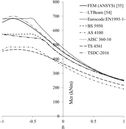
Figure 5.4 : End moment ratio (β) and Mcr for doubly symmetric I-beam with Lb = 8 m. ...57
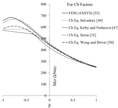
Figure 5.5 : End moment ratio (β) and Mcr for doubly symmetric I-beam with Lb = 8 m considering Cb factors. ...58
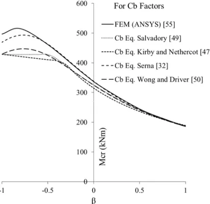
Figure 5.6 : End moment ratio (β) and Mcr for doubly symmetric I-beam with Lb = 10 m. ...58
Figure 5.7 : End moment ratio (β) and Mcr for doubly symmetric I-beam with Lb = 10 m considering Cb factors. ...59
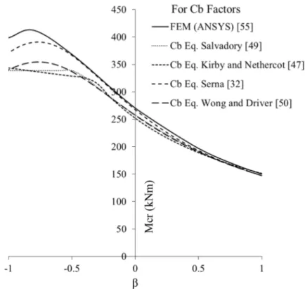
Figure 5.8 : End moment ratio (β) and Mcr for doubly symmetric I-beam with Lb = 12 m. ...59
Figure 5.9 : End moment ratio (β) and Mcr for doubly symmetric I-beam with Lb = 12 m considering Cb factors. ...60
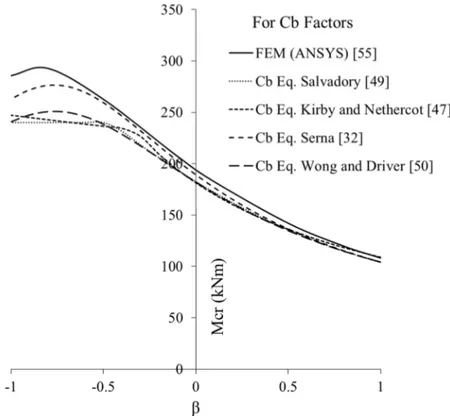
Figure 5.10 : End moment ratio (β) and Mcr for doubly symmetric I-beam with Lb = 16 m. ...60
Figure 5.11 : End moment ratio (β) and Mcr for doubly symmetric I-beam with Lb = 16 m considering Cb factors. ...61
Figure 5.12 : Fixed end beam. ...62
Figure 5.13 : Fixed end beam analysis results...62
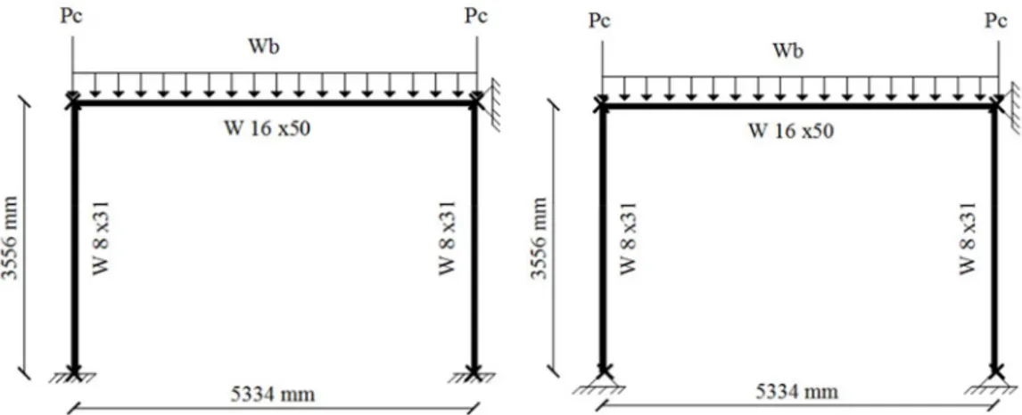
Figure 5.14 : Single-story frame with fix support and pin support. ...63
Figure 5.15 : Load parameter – beam midpoint vertical displacement of single-story frame with fix supports. ...64
Figure 5.16 : Order of plastic hinge formations (a) for fix support frame (b) for pin support frame. ...64
xx
Figure 5.18 : Peak point lateral displacements and load parameters of Ziemann
frame. ... 66
Figure 5.19 : Order of plastic hinge formations (a) lateral torsional buckling ignored (b) lateral torsional buckling considered. ... 66
Figure 5.20 : Two story and two span frame. ... 67
Figure 5.21 : Peak point lateral displacements and load parameters of two stories and two spans frame. ... 68
Figure 5.22 : Order of plastic hinge formations (a) lateral torsional buckling ignored (b) lateral torsional buckling considered. ... 68
Figure 5.23 : Three stories and two spans frame. ... 69
Figure 5.24 : Peak point lateral displacements and load parameters of three stories and two spans frame. ... 70
Figure 5.25 : Order of plastic hinge formations (a) lateral torsional buckling ignored (b) lateral torsional buckling considered. ... 70
Figure 5.26 : Simply supported beams with different unbraced conditions. ... 72
Figure 5.27 : Multi-story frame (a) braced from joints (b) braced from joints and midpoints of the beams. ... 73
Figure 5.28 : Multi-story frame analysis results. ... 74
Figure 5.29 : Order of plastic hinge formations (a) lateral torsional buckling ignored (b) lateral torsional buckling considered. ... 74
Figure 5.30 : One story and one span frame. ... 75
Figure 5.31 : Sections of one story and one span frame. ... 76
Figure 5.32 : One story and one span frame analysis results. ... 85
Figure 5.33 : Out of plane motion prevented from (a) only joints (b) mid-point of the beam (c) three points of the beam for one story frame. ... 86
Figure 5.34 : Peak point lateral displacements and load parameters of one story and one span frame. ... 87
Figure 5.35 : Out of plane motion prevented from (a) only joints (b) mid-point of the beam (c) three points of the beam for one story frame. ... 88
Figure 5.36 : Peak point lateral displacements and load parameters of two stories and one span frame. ... 89
Figure 5.37 : Order of plastic hinge formations (a) lateral torsional buckling ignored (b) lateral torsional buckling considered. ... 89
Figure 5.38 : Out of plane motion prevented from (a) only joints (b) mid-point of the beam (c) three points of the beam for one story frame. ... 91
Figure 5.39 : Peak point lateral displacements and load parameters of three stories and one span frame. ... 92
Figure 5.40 : Order of plastic hinge formations (a) lateral torsional buckling ignored (b) lateral torsional buckling considered. ... 92
xxii
NONLINEAR ANALYSIS OF STEEL FRAMES CONSIDERING LATERAL TORSIONAL BUCKLING EFFECT
SUMMARY
The use of nonlinear analysis methods is widely preferred to determine the realistic behavior of the structures through the computer technologies developed in recent years. However, the stability problems that significantly affect the structure behavior are often neglected in nonlinear analysis and in computer programs that are frequently used to the realization of these analyses. Lateral torsional buckling behavior, which is one of the stability problems, is considered to be neglected in many studies using nonlinear analysis methods in the literature. As a result, the realistic behavior of the structures cannot be achieved, the designs are carried out that the structures can carry much more load than the foreseen load carrying capacities.
Due to the necessity of achieving realistic behavior of the structures in this study, the steel frames are selected which are previously neglected in the literature for the calculation of lateral torsional buckling behavior and analyzed by nonlinear analysis methods. The steel frames are analyzed with and without considering lateral torsional buckling effect and their effect on the structure behavior are shown. Approaches presented in the regulations have been used in the analyses.
The analysis taking into account the lateral torsional buckling effect is first carried out on a single element and followed by the nonlinear analysis steps of the steel frames. The results of the analysis are given comparatively and significant effects of lateral torsional buckling on the load carrying capacity of the structure have been demonstrated. Besides, out-of-plane motions are prevented by lateral supports, the frames with different frame span lengths and floor heights are also examined. Also, TSDC and TS 4561 regulations are compared in the results of this study.
It has been observed that lateral torsional buckling reduces the load carrying capacity of the structures significantly in all the frames examined by the nonlinear analysis methods. Moreover, order of plastic hinge formations occurred in steel frames has changed and displacement capacities of frames have decreased because of the lateral torsional buckling effect. Horizontal displacements can be avoided with sufficient lateral support. Thus, the lateral torsional buckling effect can be eliminated. According to the obtained analysis results, it is concluded that lateral torsional buckling is very important in determining the actual behavior of the structures and that it should be taken into account in the analyses.
Keywords: Nonlinear analysis, lateral torsional buckling, steel frame, out-of-plane motion
xxiii
ÇELİK ÇERÇEVELERİN YANAL BURULMALI BURKULMA ETKİSİ DİKKATE ALINARAK DOĞRUSAL OLMAYAN ANALİZİ
ÖZET
Yapı davranışının gerçeğe yakın şekilde belirlenmesinde doğrusal olmayan analiz yöntemlerinin kullanılması, son yıllarda gelişen bilgisayar teknolojileri doğrultusunda yaygın olarak tercih edilmektedir. Ancak, yapı davranışını önemli ölçüde etkileyen stabilite problemleri çoğu zaman doğrusal olmayan analizlerde ve bu analizlerin gerçekleştirilmesinde sıklıkla kullanılan bilgisayar programlarında ihmal edilmektedir. Stabilite problemlerinden biri olan yanal burulmalı burkulma davranışı da literatürde doğrusal olmayan analiz yöntemlerini kullanan birçok çalışmada bu stabilite probleminin ihmal edildiği kabulü yapılarak gerçekleştirilmiştir. Bunun sonucu olarak, yapıların davranışı gerçeğe yakın şekilde temsil edilememekte, yapıların öngörülen yük taşıma kapasitelerinden çok daha fazla yük taşıyabileceğine yönelik tasarımlar gerçekleştirilmektedir.
Yapıların gerçeğe yakın davranışına ulaşılması gerekliliğinden dolayı bu çalışmada daha önce literatürde yanal burulmalı burkulma davranışını hesaplarda ihmal edildiği ve doğrusal olmayan analiz yöntemleriyle incelenen çelik çerçeveler seçilmiştir. Çelik çerçeveler yanal burulmalı burkulma etkisi hesaplarda dikkate alınarak ve alınmaksızın analiz edilerek bunun yapı davranışı üzerine etkileri gösterilmiştir. Bu analizlerin gerçekleştirilmesinde yönetmeliklerde sunulan hesap yaklaşımları kullanılmıştır.
Yanal burulmalı burkulma etkisini dikkate alan analizler ilk olarak tek bir eleman üzerinde ardından çelik çerçevelerin doğrusal olmayan analiz adımlarında dikkate alınmıştır. Analiz sonuçları karşılaştırmalı olarak verilmiş ve yanal burulmalı burkulmanın yapının yük taşıma kapasitesine olan önemli etkileri gösterilmiştir. Bunun yanında, yanal burulmalı burkulmayı etkileyen farklı düzlem dışı hareketlerin önlendiği durumlar, farklı çerçeve açıklık uzunluğuna ve kat yüksekliğine sahip çelik çerçeveler incelenmiştir. Ayrıca, Çelik Yapıların Tasarım, Hesap ve Yapım Esasları ve TS 4561 standardı bu çalışmanın sonuçlarında karşılaştırılmıştır.
Doğrusal olmayan analiz yöntemleri ile incelenen tüm çerçevelerde yanal burulmalı burkulmanın yapının yük taşıma kapasitesinde önemli oranda azalmaya neden olduğu görülmüştür. Ayrıca, çelik çerçevelerde oluşan plastik mafsal noktaları değişmiş ve çerçevelerin yer değiştirme kapasitelerinde yanal burulmalı burkulma etkisinden dolayı azalma olmuştur. Uygulanacak yeterli yanal desteklerle yer değiştirmelerin önlenebildiği ve sonucunda yanal burulmalı burkulma etkisinin giderilebildiği sonucuna varılmıştır. Elde edilen analiz sonuçlarına göre yanal burulmalı burkulmanın yapıların gerçek davranışının belirlenmesinde oldukça önemli olduğu ve analizlerde dikkate alınması gerektiği sonucuna varılmıştır.
Anahtar Kelimeler: Doğrusal olmayan analiz, yanal burulmalı burkulma, çelik çerçeve, düzlem dışı hareket
25 1. INTRODUCTION
1.1. Topic
Determining the realistic behavior of structures is an important parameter for structural engineering problems. Nonlinear analyses play a significant role for design purpose since strength and stability of the whole structure can be represented in terms of applied load and monitored displacements. Nonlinear analysis methods have computational cost and require highly trained engineers unlike linear analysis. However, in recent years, nonlinear analysis of structural steel frames becomes popular among researchers and design engineers with parallel to the development in the computer technology [1]. After these developments process, it is seen that stability conditions of the structures are also important parameter for determining the realistic behavior of the structures. In order to get the realistic results, structural stability problems have to be considered in the nonlinear analysis steps. Lateral torsional buckling is also a one the most important stability problems for slender steel structures. Therefore, lateral torsional buckling behavior should be investigated from many perspectives accounting several conditions for determining the effects on the member behavior.
In this study, nonlinear analysis of steel frames is aimed to be investigated with and without considering lateral torsional buckling behavior. A methodology based on the regulation approaches is proposed for improving nonlinear analysis of steel frames considering lateral torsional buckling.
1.2. Aim
Contemporary design codes necessitate ways to determine realistic behavior of structures. Nonlinear analyses are used extensively for design purpose since strength and stability of the whole structure can be represented. In nonlinear analyses, some assumptions for stability issues are made to ensure the unrestricted plastic
26
redistribution of moments between the frame members. In this study, a methodology is presented for improving nonlinear analysis of steel frames considering lateral torsional buckling.
The aim of the research is determining the realistic behavior of the steel frame structures and showing the importance of stability conditions on steel structure behavior using nonlinear analysis methods considering the lateral torsional buckling effect.
1.3. Scope
Nonlinear analysis methods of steel structures gained importance parallel to the development of the computing technology. Researchers and design engineers aimed to use nonlinear analysis in structural steel frames and tried to contribute to the literature in order to model the realistic structural behavior. Studies focused more on improving the methods of nonlinear analysis and various analysis techniques are developed [2]. On the other hand, stability of the steel frames are limited by checking the single member behavior and this is investigated based on member local failures. Within this scope, selected steel frames from the literature are investigated considering lateral torsional buckling in nonlinear analysis steps. Moreover, out-of-plane motions have been prevented from different length of the beam members in the analyses. Likewise, different design code approaches on lateral torsional buckling calculations are examined and the results are compared.
2. LITERATURE REVIEW
Studies related with nonlinear analysis methods and lateral torsional buckling behavior are presented in the literature. Studies examined in the literature review are given in chronological order. During this review, nonlinear analysis methods and lateral torsional buckling behavior are generally investigated separately and their effects on each other are not frequently considered. Evaluation of these studies are presented.
27
2.1. Researches about Nonlinear Analyses and Lateral Torsional Buckling Giberson [3] modeled nonlinear behavior of structural steel frames with using an end-spring model to establish the elasto-plastic stiffness equation of a beam element accounting yielding of the section.
El-Zanaty et al. [4] investigated inelastic behavior of multistory, planar steel frames. Different forms of formulation were used for stability and strength analysis. A method to compute elastic buckling loads for multistory frames were discussed. A general approach to the elastic and inelastic nonlinear analysis of multistory frames were presented and finite element formulation was developed. Also, the features of the elastic-plastic response of frames for first and second order analyses were presented. Banarjee and Raveendra [5] defined a new incremental direct solutions of two-dimensional problems of elasto-plasticity. A new direct numerical solution scheme comparable to the variable stiffness method used in the finite element analyses has been developed and applied to a number of standard plasticity problems. Analysis results were similar to the variable stiffness formulation of the finite element method. Shi and Atluri [6] studied on the elasto-plastic large deformation analysis of space frames. Complementary energy approach was the basis of work. In order to show accuracy and efficiency of the approaches, both quasi-static and dynamic loading were used when examined the numerous examples. A suppose stress approach and a plastic-hinge method were employed to get explicit expressions for the tangent stiffness matrix. For large deformations of practical interest it is essential to use a single element to model each member of the space-frame. According to the analysis results, this procedure was exact in analyzing large deformation inelastic response of frames. Gharpuray and Aristizabal-Ochoa [7] introduced a simplified nonlinear computer algorithm. This algorithm consisted of a simplified second-order elastic-plastic analysis in which the effects of bowing and the incremental part of the stiffness matrix in each member were neglected. Because of these two simplifications and as expected, load-deflection curves predicted by the proposed algorithm were slightly stiffer than those obtained by the exact second-order elastic-plastic analysis, particularly near the collapse load. The predicted collapse loads were slightly overestimated and the corresponding deflections were slightly underestimated by the proposed algorithm. It is expected that in structures with very flexible members and connections (hinged) and
28
subjected to large axial loads, the effects of bowing and the incremental part of the element stiffness matrix could become substantial and, therefore, an exact second-order analysis might become necessary.
Haldar and Nee [8] proposed an efficient second-order finite element-based method. Geometric and material nonlinear behavior of steel frames with nonlinear flexible connections and local plasticity effects were considered in this method. An obvious form of the tangent stiffness matrix of the structure was obtained that makes the proposed method extremely efficient in nonlinear analysis. The unique feature of the proposed method is that since the tangent stiffness had an explicit form and could easily be modified to consider different factors, it was extremely efficient.
Clarke et al. [9] studied on the advanced analysis. Some aspects of the inclusion of residual stresses, geometrical imperfections and capacity factors in advanced analysis were examined. An advanced analysis based on the finite element method and utilizing a distributed plasticity formulation was developed and used to perform numerical studies of the behavior of simple structural elements and frames. It was concluded that it was no longer necessary to perform member or section capacity checks with advanced analysis, because the effects of the material and geometrical imperfections and of the material and geometrical nonlinearities have already been included in the analysis.
Kim and Chen [10] presented three practical advanced analysis procedures for a two-dimensional braced steel frame design. These procedures could be used to assess realistically both strength and behavior of a structural system and its individual members in a direct manner. Also, the procedures incorporated the refined plastic-hinge concept for spread of plasticity together with practical modeling for geometric imperfections. Although the current LRFD method does not consider the effect of the weak column leaning on the stronger column, but the proposed methods were done. Liew et al. [11] concerned with second-order plastic hinge analysis of three-dimensional frame structures. They developed a computer program which used to predict accurately the elastic flexural buckling load of columns and frames by modelling each physical member as one element. It could also be used to predict the elastic buckling loads associated with axial torsional and lateral torsional instabilities, which were essential for predicting the nonlinear behavior of space frame structures.
29
Chan [12] was addressed to a review and summary of the work conducted on the non-linear analysis and design of steel frames in the past few decades from the vision of the current computer age.
Choi and Kim [13] developed optimal design of steel frame with using practical nonlinear inelastic analysis. To capture second-order effects associated with P-δ and P-Δ moment, stability functions were used to minimize modeling and solution time. The Column Research Council tangent modulus concept was used to account for gradual yielding due to residual stresses. A softening plastic hinge model was used to represent the degradation from elastic to zero stiffness associated with development of a hinge. A direct search method was used for minimum weight optimization. The practical nonlinear inelastic analysis overcame the difficulties due to incompatibility between the elastic analysis of the structural system and the limit state member design in the conventional LRFD method.
Zieman [14] described a modification to the second-order inelastic hinge method that could produce the accuracy of more sophisticated plastic zone methods in the analysis of in-plane behavior of compact doubly symmetric sections. To overcome the shortcomings of the elementary plastic hinge method, a modified tangent modulus approach was presented. It was demonstrated that a second-order inelastic hinge analysis could provide results in close agreement with those of a more sophisticated and computationally expensive plastic zone analysis.
Zhou and Chan [15] investigated the plastic hinge approach which can occur at the ends or any position along the element length. A member was divided into many elements in order to approximate the location of a plastic hinge. To describe the formation of a plastic hinge along an element in a member at the ultimate limit state, a single element capable of modeling the P-δ effect as well as the formation of the plastic hinge was needed. This work adopted a simple concept of superimposition of triangular deflected shapes due to the formation of plastic hinge to the fifth order deflection shape for elastic deflection to yield the final deflection of the element, the plastic point wise equilibrium polynomial element. After that, Chan and Zhou [16] extended previous study on geometrically nonlinear analysis of skeletal structures combined geometrically and material nonlinear analysis of slender frames using a single element per member. Three plastic hinges were allowed to form in an element with two at the two ends and one at the location of maximum combined stress due to
30
axial force and moment in the proposed element. The formulation was capable of conducting an elastoplastic buckling analysis of a beam column modeled by one element per member, which was not available in literature before.
Kim et al. [17] developed an automatic design method of steel frames using practical nonlinear analysis. The geometric nonlinearity was considered by the use of stability functions. A direct search method was used as an automatic design technique in the study. The member with the largest unit value was replaced one by one with an adjacent larger member selected in the database. The practical nonlinear analysis and the automatic design method were combined. This contribution provided much benefit to practicing engineering.
Yoo and Choi [18] proposed a new method of inelastic buckling analysis in order to determine the critical load of steel frames. This inelastic analysis was based on the concept of modified bifurcation stability using a tangent modulus approach and the column strength curve. The validity and applicability of the proposed inelastic buckling analysis were evaluated alongside elastic buckling analysis and refined plastic hinge analysis. The results revealed that the proposed inelastic buckling analysis suitably evaluated the critical load and failure modes of steel frames, and could be a good alternative for the evaluation of critical load in the design of steel frames.
Thai and Kim [19] developed a practical advanced analysis software which can be used for nonlinear inelastic analysis of space steel structures. The software employed the stability functions and the refined plastic hinge model to minimize modeling and computational time. The generalized displacement control method was adopted to solve the nonlinear equilibrium equations.
Saffari et al. [20] developed a new nonlinear method based on Homotopy Perturbation Method and was applied to elasto-plastic analysis of steel plane frames. The method developed here was applied to plane frames in which elastic perfectly plastic behavior was assumed for structural material while conventional plastic hinges of zero length were used to model plasticity effect. According to analysis results, it was showed that developed method was used for elasto-plastic analysis of structures, using various yield criteria for steel elements, less iteration was required to reach solution, and convergence was achieved very fast.
31
Doan-Ngoc et al. [21] presented a new beam-column element for nonlinear analysis of planar steel frames under static loads. The second-order effect between axial force and bending moment and the additional axial strain due to the element bending were incorporated in the stiffness matrix formulation by using the approximate seventh-order polynomial function for the deflection solution of the governing differential equations of a beam-column under end axial forces and bending moments in a correlational context. The analysis results of numerical examples proved that and the developed program from the proposed correlational element was capable of accurately predicting the nonlinear behavior of structural members and frames under the static loads.
On the other hand, previous studies considering lateral torsional buckling which is one of the stability problems has been investigated. In this part, progresses related with the lateral torsional buckling are presented with theoretical and experimental studies. Dux and Kitipornchai [22] carried out a series of experiments on the buckling of simply supported laterally continuous I-beams to investigate the influence of major axis moment gradient on the capacity of inelastic beams in the inelastic range. Nine beams were tested in three groups, each group having a different predominant moment gradient. Points of load application were prevented from moving laterally and twisting. The results demonstrate that capacity is a function of moment gradient. Beams with the less severe gradients were able to sustain higher moments than could much stockier beams in uniform bending.
Pandey and Sherbourne [23] presented a more accurate solution for the elastic, lateral torsional buckling of I-beams under unequal end moments which incorporates accurately the effects of moment gradient, lateral end restraint, and beam slenderness. The proposed analytical model was used to derive new parametric expressions for moment modification and effective length factors as design aids. This research successfully demonstrated that the conditions of loading and support directly influence warping and torsional modes, which, in turn, control the critical moment of the combined mode. The effective length factor was also found to be very useful in the limit states design of beams.
Kemp [24] described a model in order to assess the maximum moment and available inelastic rotation prior to strain weakening due to the interactive local flange and web
32
buckling and lateral-torsional buckling. The results of 44 tests on I-shaped steel beams under pure flexure and 14 tests on similar specimens under combined bending and simulated axial force were executed. The rotation capacities measured in these tests were examined in terms of standard local and lateral buckling parameters as well as the proposed model.
Helwig et al. [25] conducted finite element buckling analyses of singly symmetric I-shaped girders subjected to transverse loading applied at different heights on the cross section. For single-curvature bending, the finite element results showed that traditional values of moment gradient factors can be used to estimate the buckling capacity of singly symmetric girders. Moreover, the finite element results demonstrated that the height of load application on the cross section has a significant effect on the buckling capacity.
Trahair and Pi [26] summarized a series of investigations into the behavior, analysis and design of members subjected to combined torsion and bending because of torsion was generally ignored by designers. Steel torsion members might be designed for local buckling or plastic collapse.
Papangelis et al. [27] presented a computer program for or the elastic flexural torsional buckling analysis of a wide range of beams, beam-columns, and plane frames. It was designed to assist designers to implement the method of design by buckling analysis which is permitted in modern structural steel design standards, either explicitly or implicitly. This computer program makes a first-order elastic analysis of the in-plane behavior of the frame, and then uses the results of this in a finite element analysis of the elastic flexural torsional buckling of the frame out of its plane. The program also uses the method of design by buckling analysis to design beams.
Suryoatmono and Ho [28] studied on the equations for evaluating the moment-modification factor (Cb) because the equations which presented in AISC 1994 [29]
edition given incorrect results for some moment diagrams. From the results, it was shown that the equations for evaluating the Cb factor in both editions (1986 [30] and
1994 [29]) of the AISC Specifications were not accurate for some of the cases considered in this paper. Therefore, instead of using one single equation for any moment diagram, alternative equations for evaluating the Cb factor for each loading
33
Lim et al. [31] investigated the elastic lateral torsional buckling of I-beams under linear moment gradient that very precisely incorporates the effects of moment gradient and various end restraints. The elastic critical buckling moments were obtained independently by using the Bubnov–Galerkin method and the finite element method. According to analysis results, alternative equations were proposed in order to evaluate the moment gradient correction factor with considering end restraint conditions. Serna et al. [32] focused on the equivalent uniform moment factor which is used to compute the elastic critical moment. Results obtained using both finite elements and finite differences. The new values refer to the equivalent uniform moment factor for linear moment distributions, uniform distributed loading and concentrated load with two and one end moments. All these cases have been solved considering all possible end support conditions: no prevention to lateral bending and warping; prevention to lateral bending and warping; and prevention to lateral bending or prevention to warping. The results show that warping prevention leads to a significant increase in the coefficient. The paper has presented a closed-form expression to obtain the equivalent uniform moment factor for any moment distribution.
Aydin [33] developed a stiffness matrix for the elements of framed systems which are under constant axial force and moment. The procedure presented here considers the second-order effects due to the axial forces on the bars which are used to calculate the critical buckling loads of the framed system. This approach provides more accurate and dependable results than the energy methods.
Taras and Grenier [34] proposed a new analytical description of buckling curves for lateral torsional buckling. The proposal made in this paper represented a clear improvement of the accuracy and consistency of the analytical description of lateral torsional buckling curves.
Bradford and Pi [35] investigated the lateral-torsional buckling of a pin-ended circular arch with a uniform thin-walled cross section that was subjected to a uniform radial load. It was demonstrated by comparisons with the FE results that the solution provided good predictions for the lateral torsional buckling loads of both shallow and deep arches.
Wu and Mohareb [36] developed a finite element formulation for the lateral torsional buckling analysis of plane frames with moment connections consisting of two pairs of
34
welded plate stiffeners. The study developed a joint finite element, which accurately quantifies the partial warping restraint provided by common moment connections to adjoining members framing at right angles. The new element provided a more accurate representation of the joint stiffness than the continuous warping deformation assumption.
Kucukler et al [37] presented a stiffness reduction approach utilizing linear buckling analysis with developed stiffness reduction functions for the lateral torsional buckling assessment of steel beams. The proposed method was verified against the results obtained through nonlinear finite element modelling. The proposed stiffness reduction method obviated the need for using lateral torsional buckling assessment equations and considers the influence of the development of plasticity on the response of steel beams, so offering a realistic and practical means of design.
Ozbasaran et al. [38] presented an alternative design procedure for lateral torsional buckling of cantilever I-beams which aims to simplify the calculation of critical loads and design moments. It was seen that the presented design curve was in good agreement with mentioned steel design codes.
2.2. Literature Evaluation
Having examined the literature about nonlinear analysis, nonlinear analysis is a key issue determining the realistic behavior of structures. Previously, nonlinear analysis methods were complex and time consuming for researchers. However, developments in the computer technology make it easy and help to use it widely in the structural analysis among the structural engineers. In this development process, it is observed that not only nonlinear analysis procedures but also structural stability behavior has significant influence on the design of structures.
In order to determine realistic behavior of structures, nonlinear analyses and structural stability conditions have to be considered together in the analyses. In which, lateral torsional buckling is one of the most important stability problems for especially slender steel structures. However, after examining the literature works, it is seen that this stability problem is not considered in nonlinear analysis steps. Consequently, lateral torsional buckling behavior is investigated from many perspectives accounting several conditions for determining the effects on the member behavior but this works are
35
generally performed on a single member scale. Moreover, effects of lateral restraints on torsional and flexural buckling of members are examined for elastic and inelastic ranges. Additionally, moment factors of beams, geometric imperfection effects and curved members are discussed and influences on the member behavior are focused. Also, approaches using finite elements and experimental studies are performed to evaluate lateral torsional buckling behavior.
As a conclusion, both subjects of nonlinear analyses and lateral torsional buckling have progressed separately and there were limited works linked to each other. Therefore, need to use lateral torsional buckling effect in the nonlinear analyses has been the basis of this study.
3. ANALYSIS METHODS
In this study, nonlinear analysis methods are used to determine behavior of steel frames considering lateral torsional buckling. For this purpose, various structural steel design standards are used to determine the design parameters.
3.1. Nonlinear Analysis of Steel Frames
Many of the nonlinear formulations of steel structures presented in the literature are based on the displacement method, for its relative ease in implementation [39]. Nonlinearities in structures exist in two forms, these are geometrical and material nonlinearities. Geometric nonlinearities gives P-Δ effects which is directly reflected in second-order analysis. Material nonlinearities emerge when material yield or stress-strain behavior shows nonlinear characteristics. In which, two models of material nonlinear frame analyses arise depending on the degree of the accuracy. These are concentrated plasticity (plastic hinge) model and distributed plasticity (plastic zone) model. Plastic hinge model ignores the progressive yielding that takes place in cross section, likewise, plastic zone method takes into consideration the spread of yield in the cross section. In plastic hinge method, yielding is also assumed to be concentrated in a small region of zero length, generally termed as the plastic hinge. Although the plastic zone approach yields results that are very close to the reality, it is limited to use
36
due to the difficulties that modeling systems have in modeling and the resolution time of these models is very long. Therefore, a popular approach for modelling nonlinear behavior of steel frames is concentrated plastic hinge method.
In nonlinear analysis of steel frames, the load parameter leading to the formation of the first plastic hinge is computed. After determining the location and load parameter of first plastic hinge, member is assumed to remain elastic except at places where zero length plastic hinges are allowed to form. Plasticity is formulated based on the members cross sectional constitutive model that represents the plastic interaction between the axial force and the bending moments. Plastic hinges are located when the section internal forces exceed the plasticity criterion. This is repeated in step by step manner until losing of mechanism of behavior or stability of the structure. Nonlinear analysis of steel frames aims to determine the global behavior of structures instead of isolated member checks that linear analysis methods uses. For steel structures, the plastic interaction curve representing full yielding of the cross section is expressed by the design codes. A graphical comparison of the load-deflection behavior of a plane frame with using previously mentioned conditions are given in Figure 3.1.
Figure 3.1 : General analysis types of framed structures [12]. 3.1.1. First-order elastic-plastic analysis
First-order elastic-plastic analysis is one of the most basic type of nonlinear analyses and effects of the change of geometry are ignored in this analysis. This method models the effects of section yielding under incremental loading. Consequently, it does not
37
consider second-order stability effects [40]. The plastic limit load can be gained directly by a simple elastic-plastic analyses. An elastic-plastic hinge idealization of the cross section behavior is used in the formulation of first-order elastic-plastic analysis. Members in a structure are assumed to be fully elastic prior to the formation of the plastic hinges. Perfectly plastic hinges are used to account the inelastic behavior by inserting in the member where the full plastic strength is reached.
According to AISC 360-10 LRFD [41], cross section’s plastic strength is defined using (3.1) and (3.2). 8 1 0 9 y p P M . P M for y 0 2 P . P (3.1) 1 0 2 y p P M . P M for y 0 2 P . P (3.2)
Relation between (3.1) and (3.2) is given in Figure 3.2 and this curve is called as the bilinear interaction curve. The average I-shapes accounting AISC 360-10 LRFD [41] interaction equations is plotted.
Figure 3.2 : Bilinear interaction curve.
Moment and normal force are written according to load parameter and (3.3) and (3.4) are used;
Mi1Mi p M (3.3)
38
Obtained values from (3.3) and (3.4) are inserted in (3.1) or (3.2). There are two cases [42];
For 1.case 0 2
y P
.
P , load parameter is decided using (3.5);
9 9 8 9 8 p p p i i p p p M P M P M P p M P M P (3.5) For 2.case 0 2 y P .
P , load parameter is decided using (3.6);
2 2 2 p p p i p i p p P M M P P M p P M P M (3.6) After every hinge is formed, joint displacements and internal forces of members are calculated using (3.7), (3.8) and (3.9), respectively.
p1 1 p2 2 (3.7) ... pi i
M p M1 1 p2 M2 ... p Mi i (3.8)
P p1 P1 p2 P2 (3.9) ... p Pi i
Total load parameters are calculated until the structure reach ultimate load carrying capacity. (3.10) is used in order to calculate ultimate load parameter of the structure. 1 2 3 1 n p n i i p p p p ... p p
(3.10) Plastic moment and normal force capacity are defined in (3.11) and (3.12). These are used in the nonlinear analysis steps.Mn Mp FyZx (3.11) Pp FyA (3.12) 3.1.2. Second-order elastic-plastic analysis
Second-order elastic-plastic analysis takes account of geometry changes which are associated with the increase of P-Δ effects (sway deflection) [40]. Moreover, the effect of the geometric changes of the frame and frame elements on the equilibrium equations can be calculated by considering the second-order theory. For second-order analysis
39
of steel structures, stability functions, geometric stiffness matrices and iterative vertical loads and fictitious horizontal load practical calculation approaches can be used. In TSDC-2016 [43] and AISC 360-10 [41], the moment coefficients method, also known as the B1 - B2 method, is used for practical second-order analysis. In the
moment coefficients method, the internal forces obtained from the analysis of the first-order analysis are increased indirectly with certain coefficients by the second-first-order effects. In this method, the effects of element shape changes (P-δ) and system displacement effects (P-Δ) are taken into consideration. In Figure 3.3, procedure for second-order analysis is given.
Figure 3.3 : Procedure for second-order analysis using B1-B2 method [44].
The effect of the geometric changes of the frame and frame elements on the equilibrium equations can be calculated by considering the second-order theory. (3.13) (3.14), (3.15) and (3.16) are presented in AISC 360-10 [41];
Mr B M1 nt B M2 lt (3.13) 2 r nt lt P P B P (3.14) 1 1 1 m r el C B P P (3.15) 2 1 1 1 story e ,story B P P (3.16)
40 4. LATERAL TORSIONAL BUCKLING
There are three major fields which are related with the stability designs of steel frame structures. These are global buckling, local buckling and structural instability due to the plastic hinge formation. Lateral torsional buckling is a form of global buckling and it is focused in this part. Lateral torsional buckling is a behavior which is one of the instability conditions induced by the compressed flange of unrestrained beam subjected to bending around the major axis. If a beam reaches the critical moment value under the applied load or moment, this beam may expose to lateral torsional buckling failure. The critical moment is a function of lateral and torsional stiffness. This is affected by the boundary conditions, unbraced length, material nonlinearities, load pattern and dimensions of the member cross section. If a beam is under the influence of lateral torsional buckling, it experiences simultaneous in-plane displacement, lateral displacement and twisting because of bending. Lateral displacement and twisting of the simply supported beam under the bending moment considering lateral torsional buckling behavior is shown in Figure 4.1.
Figure 4.1 : Lateral displacement and twisting of the simply supported I-beam subjected to bending moments [45].
4.1. Methods of Stability Analysis
Understanding of structural stability conditions have not been achieved exactly and ignored mostly in the analysis of steel structures. Therefore, design engineers have encountered a number of failures because of the lack of understanding these stability
41
requirements. Beams are one of the main structural members and resist the applied load by bending and shearing actions. Open cross sections like I-shape beams have very low torsional rigidities and their resistance to torsional instability is very limited. As a result of this, they are mainly vulnerable against lateral torsional buckling effect. There are two types of torsional rigidity that might exist in a member with thin plate cross section. They are uniform torsion and non-uniform torsion [45].
4.2. Uniform Torsion of Thin-Walled Open Sections
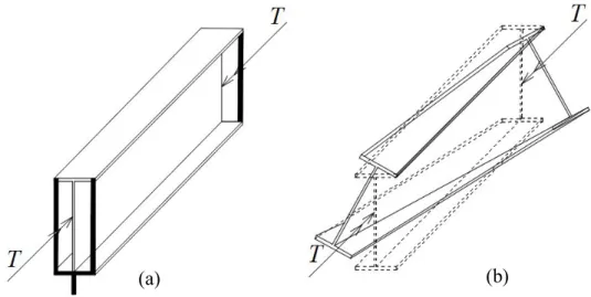
A simply supported beam under an equal and opposite twisting moment is shown in Figure (4.2). Under this condition, the twisting moment along the length of the member is constant and a uniform torsion occur in the beam member, it is showed in Figure 4.2 (a). Also, warping of the cross section arise because of this torque. Figure 4.2 (b) illustrates warping of I section beam under uniform twisting moment.
Figure 4.2 : Simply supported I-beam (a) subjected to twisting moment (b) warping of I-section under uniform twisting moment.
Warping of all the cross sections is unrestrained for simply supported beam and this is caused twisting moment by applied torque T. Torque is also attacked only by shear stresses developed in the cross section of beam member. These stresses act parallel to the edge of the component plates of the cross section, as shown in Figure 4.3.
42
Figure 4.3 : St. Venant shear stress distribution due to uniform torsions in an I-section.
These shear stresses are called St. Venant shear stresses. The torsion is related with these shear stresses and is stated to as St. Venant torsion, Tsv. The St. Venant torsion
expressed in (4.1) is also referred to as uniform or pure torsion. d / dz is the rate of twist. sv d T GJ dz (4.1)
4.3. Non-Uniform Torsion of Thin-Walled Open Sections
A cantilever beam subjected to a torque T is shown in Figure 4.4. This torque is applied at the free end of the beam. At the fixed end, warping is prevented but at the free end, warping is free. Therefore, the applied torque is resisted merely by St. Venant torsion at the free end. As a result of this, in addition to St. Venant torsion, there exists another type of torsion known as warping restraint torsion in the cross section. There are also axial stress in addition to shear stress because the cross section is prevented from warping. These axial stresses occur at the fixed end of the beam. Emerged these axial stresses in the two flanges creates a pair of equal moments. These moments are called as the bi-moment Mf which act oppositely in each of these two planes of the flanges.
43
Figure 4.4 : A cantilever beam subjected to a twisting moment at the free end. The bending moment Mf in either the top or the bottom flange is calculated as (4.2).
There are also occurred the shear forces V in both flanges and opposite directions associated with the bending moment. (4.3) is used to calculate the shear forces. These arisen bending moments and shear forces are illustrated in Figure 4.5.
2 2 f f f d u M EI dz (4.2) 3 3 f f f f dM d u V EI dz dz (4.3)
Figure 4.5 : Moment and shear developed at the fixed-end cross section of an I-section due to non-uniform torsion
44
This pair of shear forces create a couple acting on the cross section. The resulting torsion, which is referred to as non-uniform torsion Tw, is given by (4.4). h is the
distance between the shear forces.
T
w
V h
f (4.4)Non-uniform torsion can also be written as (4.5)
2 3 3 3 3 2 w f w h d d T EI EC dz dz (4.5) In which, warping constant of the I-section, Cw is decided to use (4.6). It is important
that warping constant is different for each of the cross section.
2 2 f w I h C (4.6)
When the member is twisted and the applied twisting moment is resisted by St. Venant torsion and warping restraint torsion, the internal twisting moment T equals to (4.7).
T
T
sv
T
w (4.7)The internal twisting moment can be defined as (4.8) considering (4.1) and (4.5).
3 3 w d d T GJ EC dz dz (4.8)
4.4. Lateral Buckling of Beams
If a beam is bent about its axis of greatest flexural rigidity, out-of-plane bending and twisting may occur when the applied load reaches its critical value, unless the beam is provided with a necessary lateral support. The following situations are mentioned and examined by Chen and Lui [45].
4.4.1. Simply supported beam under pure bending
When a simply supported I- section beam subjected to a couple of equal and opposite end moments, in addition to St. Venant torsion, there is also a warping restraint torsion. The external moments at any cross section are given in (4.9), (4.10) and (4.11) for each axis.
45
Mx'( ext ) Mx( ext ) M0 (4.9) My'( ext ) Mx( ext ) M0 (4.10)
z'( ext ) x( ext ) 0
du du
M M M
dz dz
(4.11) The corresponding internal resisting moments are also given in (4.12), (4.13), and (4.14) for each axis.
2 2 x'(int) x d v M EI dz (4.12) 2 2 y'(int) y d u M EI dz (4.13) 3 3 z'(int) w d d M GJ EC dz dz (4.14) The corresponding external and internal moments for an I-beam according to axes are given in (4.15), (4.16), and (4.17), respectively.
2 0 2 0 x d v EI M dz (4.15) 2 0 2 0 y d u EI M dz (4.16) 3 0 3 0 w d d du GJ EC M dz dz dz (4.17) The first equation is not interested in the calculations because it describes the in-plane behavior of the beam before lateral buckling. Therefore, the lateral-torsional buckling behavior of beam can be gained from the combination of the last two equations. This combining equation is given in (4.18).
2 4 2 0 4 2 0 w y M d d EC GJ EI dz dz (4.18)
By solving this equation considering the simply supported conditions, the critical moment can be calculated as (4.19) [46].
46 2 2 1 w ocr y EC M EI GJ L L GJ (4.19)
Describing equation (4.19) is supposed that the in-plane deflection has no effect on the lateral torsional buckling behavior of the beam. This can be justified if the major axis flexural rigidity is greater than the minor axis flexural rigidity. However, if flexural rigidities of major and minor axis are of the same of order of magnitude, the effect of bending in the vertical plane direction may be important and should be considered in calculating Mcr. This solution is more complicated and an approximate solution was
given by Kirby and Nethercot [47] in (4.20).
2 2 1 1 y w ocr y x EI GJ EC M L ( I / I ) L GJ (4.20) According to this formula, lateral torsional buckling never happens in circular cross sections or square box sections in which all the component plates have the same thicknesses. This formula also indicates that lateral torsional buckling occurs when the load is applied on the plane of weak axis.
4.5. Design of Members Subjected to Lateral Torsional Buckling Effect 4.5.1. Australian Standard – (AS 4100)
Australian steel design standard AS 4100 [48] gives nominal member moment capacity under lateral torsional buckling with (4.21).
Mb m sMs Ms (4.21) αm and αs factors are calculated according to (4.22) and (4.23).
2 2 2 2 3 4 1 7 2 5 m m . M . M M M (4.22) 2 0 6 s 3 s s oa oa M M . M M (4.23)
47
Ms is nominal section capacity, Moa is reference buckling moment which is obtained
from elastic analysis of simply supported beams under a uniform bending moment and is given in (4.24). 2 2 2 2 y w oa e e EI EI M GJ l l (4.24)
4.5.2. American Design Specification – (AISC 360-10 / LRFD)
AISC 360-10 [41] specification presents an approach for checking the lateral torsional buckling effects for the steel frame members. This approach is classified into subcategories considering unbraced length limits and the section features such as section type, modulus of elasticity, elastic and plastic section modulus.
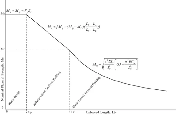
For beams of compact sections, there are two possible types of failure: (1) plastic yielding, (2) lateral torsional buckling. The design curve is shown in Figure 4.6.
Figure 4.6 : Nominal flexural strength and unbraced length graphic under lateral torsional buckling for I-shaped members.
The unbraced length limits are given in (4.25) and (4.26) according to AISC 360-10 [41] specification : p 1 76 y y E L . r F (4.25)
![Figure 3.1 : General analysis types of framed structures [12]. 3.1.1. First-order elastic-plastic analysis](https://thumb-eu.123doks.com/thumbv2/9libnet/3709198.24928/36.892.228.602.622.953/figure-general-analysis-framed-structures-elastic-plastic-analysis.webp)
![Figure 4.1 : Lateral displacement and twisting of the simply supported I-beam subjected to bending moments [45]](https://thumb-eu.123doks.com/thumbv2/9libnet/3709198.24928/40.892.135.704.621.892/figure-lateral-displacement-twisting-supported-subjected-bending-moments.webp)