Additive Manufacturing of Anatomical Models from
Computed Tomography Scan Data
Y. Gür∗
Abstract: The purpose of the study presented here was to investigate the
manu-5
facturability of human anatomical models from Computed Tomography (CT) scan
6
data via a 3D desktop printer which uses fused deposition modelling (FDM)
tech-7
nology. First, Digital Imaging and Communications in Medicine (DICOM) CT
8
scan data were converted to 3D Standard Triangle Language (STL) format by using
9
InVaselius digital imaging program. Once this STL file is obtained, a 3D physical
10
version of the anatomical model can be fabricated by a desktop 3D FDM printer.
11
As a case study, a patient’s skull CT scan data was considered, and a tangible
ver-12
sion of the skull was manufactured by a 3D FDM desktop printer. During the 3D
13
printing process, the skull was built using acrylonitrile-butadiene-styrene (ABS)
14
co-polymer plastic. The printed model showed that the 3D FDM printing
technol-15
ogy is able to fabricate anatomical models with high accuracy. As a result, the skull
16
model can be used for preoperative surgical planning, medical training activities,
17
implant design and simulation to show the potential of the FDM technology in
med-18
ical field. It will also improve communication between medical stuff and patients.
19
Current result indicates that a 3D desktop printer which uses FDM technology can
20
be used to obtain accurate anatomical models.
21
Keywords: 3D printing, rapid prototyping, CT scan data, anatomical modelling,
22
FDM.
23
1 Introduction
24
Rapid Prototyping (RP) is an Additive Manufacturing (AM) technology rapidly
25
developed throughout the 1980’s and 1990’s. Additive manufacturing allows to
26
make prototypes or parts quickly on demand and any design modifications can be
27
made without adding extra cost [1, 2, 3, 4, 5, 6]. MakerBot® company intended
28
to democratize the rapid prototyping technology by offering an open source 3D
29
∗Balikesir University, Mechanical Engineering Dept., Cagis Campus 10145, Balikesir/TURKEY.
FDM printer called MakerBot. The printer uses open filament system and as a
30
raw material ABS and Polylactic Acid (PLA) plastic filament [7]. 3D printers are
31
going to affect every face of life because any complex or customized parts can be
32
fabricated in a short period of time and with less waste of material and lower carbon
33
emission [8].
34
The following rapid prototyping techniques are the most commonly used systems.
35
These are stereolithography (SL), selective laser sintering (SLS), (FDM), ink jet
36
printing (IJP), laminated object manufacturing (LOM), 3D printing (3DP), and
37
multi jet modelling (MJM) [9,10].
38
FDM technology is a layered additive manufacturing process which uses
thermo-39
plastic material such as ABS and PLA to produce concept models, functional
pro-40
totypes, manufacturing aids and low volume end-use parts. The FDM process
be-41
gins by slicing 3D CAD data into layers. Then the data is transferred to a desktop
42
3D printer. The thermo-plastic material is uncoiled slowly and extruded through
43
heated extrusion nozzle. The material is precisely laid down upon the precedent
44
layers. Following each sequence the building platform is lowered down by the
45
thickness of one layer while the extrusion nozzle continues to move in a horizontal
46
X-Y plane. The process is repeated, adding layer upon layer, until the object is
47
finished (see Fig. 1).
48
In this step, travel movements of the extrusion nozzle and if necessary support
49
structure to hold the part upright position on the building platform and to support
50
leaky connections, overhangs, cavities and bridges, are also generated. Once the
51
part is completed these support scaffoldings can be removed off by hand. The
52
slicing information is then exported to “gcode” or “x3g” file format that 3D FDM
53
printer can understand to print the model. FDM technology is used in a wide range
54
of industries such as automotive, aerospace, industrial design, consumer
electron-55
ics, fashion, food and even in medical world [11].
56
Van Nunen et al. [12] fabricated stereolithographic skull models for five patients to
57
be used in the surgical planning and as a result they demonstrated that the models
58
had improved communication to kins and supported the training of residents. Sinn
59
et al. [13] are also used SL method for craniofacial surgery because it provides
60
highly accurate models and additional information in treatment planning. But they
61
mentioned that stereolithograpic process added extra cost for the procedure and
62
this is to be a hindrance to its widespread acceptance in clinical pratice. D’Urso
63
et al. [14] fabricated the biomodels by using SLS method. They also reported that
64
biomodelling is facilitated diagnosis, operative planning and communications
be-65
tween medical stuff and patients. On contrary, they pointed out that manufacturing
66
time and cost are high. Sailer et al. [15] manufactured 20 patient’s craniofacial
67
biomodels with selective laser melting method and they mentioned that main
dis-68
advantage of the process is expensiveness and the models are thin and fragile and
69
when the models are taken apart and reassembled for simulation purposes the
orig-70
inalty of the model is definitively lost. A 3D desktop printer costs around $1000 is
71
used in this study. The cost of consumable material used for the production of parts
72
is so cheap and 1kg filament of ABS is as low as $29. 1: 2 scaled model of the
73
skull can be produced in 6 hours. Anatomical skull models previously fabricated
74
with variety of additive manufacturing methods but in this study, as a new, the skull
75
model is manufactured with FDM technology both in a short period of time and
76
very cheaply.
77
2 Building the anatomical model
78
The term “CT scan” is a representation of multiple X-ray images of structures of
79
a human body on a display. The word “tomography” comes from the Greek word
80
“tomos” which means slice and the word “graphein” means write [16]. It is
pos-81
sible to manufacture three dimensional tangible examples of anatomical models
82
of human body with the developments in medical based modelling technologies.
83
Anatomical model of a human body organ can be generated by collating of attained
84
CT scan data. These digital models can be manufactured with rapid prototyping
85
methods and these tangible models can be used for preoperative planning,
nosis, therapy choices, teaching purposes, surgical simulation and medical device
87
prototyping. These physical models could be very useful for planning very
com-88
plex surgeries. Moreover, it is quite easy to manufacture a customized implant if
89
there is 3D tangible anatomical model of a human organ [17].
90
In this paper, the manufacturability of anatomical models from 2-D DICOM CT
91
scan data via converting those to 3D STL data by a desktop 3-D FDM printer is
92
evaluated. A case study is also enclosed to show that how intangible digital
medi-93
cal data comes to life as a tangible object through the FDM method. The geometry
94
of the anatomical skull is quite complicated and cannot be manufactured with
clas-95
sical cutting processes such CNC milling or extremely difficult to produce because
96
it has intricate details. In this point rapid prototyping technology can be
help-97
ful. Fabricated anatomical physical model of a skull facilitate surgery planning,
98
rehearsal of the operation by marking, drilling, cutting and so on without having
99
time pressure. Having physical object in hand is not only useful for communication
100
between medical personnel but also useful for presentation of the operation details
101
with the patient and its kin [10].
102
The process of manufacturing of anatomical models from CT scan data via 3D
103
FDM printer has six steps. They are;
104
• Data acquisition via CT Scan,
105
• Generating a 3D model from CT scan data and solid, shell or hollow CAD
106
design of the model,
107
• Exporting the CAD model to STL file format,
108
• Slice the model into layers, generate the travel movements and support
struc-109
ture if necessary,
110
• 3D print the anatomical model,
111
• Remove the support material and apply finishing process [18, 19, 20].
112
2.1 Data acquisition via CT scan
113
As input data, a conventional hospital CT scanner’s data are used. For the
pur-114
pose of medical visualization, CT scan can provide detailed information about the
115
anatomical structure in a layered format. First step generating a correct anatomical
116
skull model is to strip bone structure from CT scan data. CT scans of an anonymous
117
patient’s skull are obtained. The thickness of the slices of the CT scan is 1 mm in
118
average. Size of DICOM data files are 515 Kbytes.
2.2 3D modelling of the skull from CT scan data
120
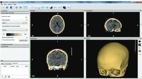
160 DICOM files are processed in InVesalius v3.0 software during the skull
strip-121
ping process (see Fig. 2). InVesalius, which is a multi-platform free and open
122
source software package for visualization and medical imaging, is used for
elim-123
ination of soft tissues and stripping of skull bone structure [21]. In order to strip
124
the skull structure from soft tissues correctly threshold value is chosen as 246.
125
InVesalius has exporting facility of 3D models as STL file format that is rapid
126
prototyping’s standard data transmission format to fabricate physical object of an
127
anatomical model by using a rapid prototyping technology. The “.STL” file is
fur-128
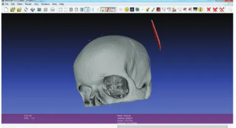
ther processed in open source MeshLab processing and editing of unstructured 3D
129
triangular meshes software in order to remove floating substances not attached to
130
the anatomic model and for smoothing (See Fig. 3) [22].
131
Figure 2: Skull stripping in InVesalius medical image program.
3 Manufacturing the anatomical model
132
The anatomical skull model is printed on a Flashforge Creator dual extruder 3D
133
FDM printer in the department of mechanical engineering of Balikesir University.
134
Its dimensions are 467 x 320 x 381 mm and small enough to use on a desktop in an
135
office room. Building volume of the printer is 225x145x150 mm. Layer thickness
136
can be changed between 250 µm and 100 µm. As a building material either ABS
137
(C8H8)x(C4H6)y(C3H3N)z) or biodegradable PLA (C3H4O2)nthermo plastics can
138
be used. It uses open filament system and works with filaments 1.75 mm in
diame-139
ter. Open source ReplicatorG 0040 or MakerBot® MakerWare™ v2.4 can be used
Figure 3: Removing of floating substances not attached to the anatomic model in MeshLab.
as slicing software. MakerBot® MakerWare™ program support “.STL” file format
141
and can load it without any problem [23]. MakerWare™ 3D printing software is
142
used for pre-processing and slicing of the anatomical model. Initially, the skull
143
model is located on the build platform, scaled to 1:2, and orientated. In the slicing
144
step of the anatomical model, MakerWare™ slices the 3D model into finite
num-145
ber of layers. For this study, 344 layers have been generated by the MakerWare™
146
software (see Fig. 4).
147
The thickness of the each layer for the model is 150 µm. This slicing step not only
148
contains slicing procedure but also consists of generating travel movements for the
149
extrusion nozzle and model support structure that holds the model upright
posi-150
tion and prevent the leaky connections, overhangs, bridges, internal cavities. The
151
anatomical model requires support structure because it has overhangs, bridges,
cav-152
ities, and delicate details (see Fig. 4). For the creation of the model 23 gr (including
153
support material) ABS thermo plastic was used and building time took 10 hours.
154
The building platform of the 3D printer is heated to 110oC before printing because
155
ABS plastic does not stick on to the building platform even though platform is
cov-156
ered with kapton tape which adheres to ABS very well and prevents ABS parts from
157
warping. On the other hand, the extrusion nozzle heated up to 230oC in order to
158
make flow the ABS plastic smoothly. During the printing process, extrusion nozzle
159
moves along the X-Y axis and the building platform goes down in Z axis. The skull
160
model fabricated in the department of mechanical engineering of the University of
Figure 4: Slicing of the skull in MakerWare™ slicing - printing software.
Balıkesir is presented in Fig. 5. Following the production of the anatomical model,
162
support structures removed by hand.
163
4 Conclusion
164
The main goal of this study was to validate the manufacturability of anatomical
165
models from 2D DICOM individual CT scan data via converting those 3D STL
166
data by a desktop 3D FDM printer. The case study showed that intangible digital
167
medical data also comes to life as a tangible object through the FDM method.
168
Even though anatomical skull models previously fabricated with variety of additive
169
manufacturing methods, the cost of the models was high and fabrication time was
170
longer than the FDM one. Moreover, approved materials, which can be sterilized,
171
are available for medical use in FDM technology [24]. In this study, as a new, the
172
skull model is manufactured with FDM technology both in a short period of time
173
and very cheaply. Seeing this bio-model by the patients can help them to improve
174
their understanding of the surgical operation.
175
It can be concluded that rapid prototyping in medicine is an emerging technology
176
and has enormous potential for variety of medical applications like preoperative
177
planning, diagnosis, therapy choices, teaching purposes, surgical simulation and
178
medical device prototyping. However it is not used in everyday clinical practices
179
yet because of its current limitations such as the time that needed for producing
180
a 3D anatomical object and very important in emergency cases. Fabrication time
181
ranges between couple of hours to couple of days. Of course this is no acceptable
182
for emergency cases. But in near future it will increase its utilization in medical
183
field hugely and also academic research activities will expand.
184
Acknowledgement: The author acknowledges the funding by the Balıkesir
Uni-185
versity’s Scientific Research Projects Unit through the Project No: Mak.BAP: 2013.
186
0003, Tracking Number: 33.100.2013.0001.
187
References
188
1. Hull, C. W. (1986) U.S. Patent 4,575,330 (Publication Date: 3/11/1986; Fil-ing Date 8/8/1984). http://www.google.com/patents/US4575330.
2. Lim, C. S., Chua, C. K. & Leong, K.F. (2003) Rapid Prototyping, World Scientific, Second edition.
3. Cooper, K. G. (2001) Rapid Prototyping Technology, Selection and Applica-tion, Marcel Dekker Inc.
4. Crawford, S. (2013) http://computer.howstuffworks.com/3-d-printing1.htm/ 5. Rosen, D.; Gibson, I. & Stucker, B. (2010) Additive Manufacturing
Tech-nologies, Springer.
6. Knill, O. & Slavkovsky, E. (2013) Cornel University Library, arXiv:1306. 5599[math.HO].
7. Rosen, D. E. (2014) Retrieved from Commercial Observer. http://commer-cialobserver. com/2012/05/makerbot-industries-to-print-anything-and-every thing-at-one-metrotech/ (05.09.2014).
8. Rowan, D. (2011) Retrieved from WIRED Business Future Shock. http:// www.wired.com/2011/05/3d-printing-an-industrial-revolution-in-the-digital-age/ (05.09.2011)
9. Kruth, J. P., Leu, M. C. & Nakagawa, T. (1998) Annals of the CIRP, 47, 2, 525-540.
10. Giannatsis, J. & Dedoussis, V. (2009) Int. J. Adv. Manuf. Technol., 40, 116-127.
11. Berman, B. (2012) Business Horizons, 55, 155-162.
12. Van Nunen, D. P. F., Janssen, L. E., Stubenitsky, B. M., Han, K. S. & Mu-radin, M. S. M. (2014) Journal of Cranio-Maxillo-Facial Surgery, 42, 959-965.
13. Sinn, P. D., Cillo Jr, J. E. & Miles, B. A. (2006) The Journal Of Craniofacial Surgery, 17, Number 5 869-875.
14. D’Urso, P. S., Atkinson, R. L., Lanigan, M. W., Earwaker, W. J., Bruce, I. J., Holmes, A., Barker, T. M., Effeney, D. J. & Thompson, R. G. (1998) British Journal of Plastic Surgery, 51, 522-530.
15. Sailer, H. F., Haers, P. E., Zoilikofel, C. P. E., Warnke, T., Carls, F. R. & Stucki, P. (1998) Int. J. Oral Maxillofac. Surg., 27, 327-333.
16. Computed Tomography, (2014) http://www.fda.gov/Radiation-Emitting Prod-ucts/ RadiationEmittingProductsandProcedures/MedicalImaging/MedicalX-Rays/ucm115317.htm, Last accessed: 20.6.2014
17. Berce, P., Chezan, H. & Balc, N. (2005) ESAFORM 2005 Conference, Cluj-Napoca, Romania, 697-682.
18. Palousek, D. & Rosicky, F. (2014) Rapid Prototyping Journal 20/1, 27–32. 19. Marcincin, J. N., Marcincinova, L. N., Barna, J. & Janak, M. (2012) Tehniˇcki
Vjesnik19, 3, 689-694.
20. Gür, Y. (2013) East of West West of East International Balkans Conference, 5-8, June 2013, Prizren/Kosovo, 66.
21. InVesalius v3.0 (2014) http://www.cti.gov.br/invesalius/, Last accessed on 24.06.2014
22. MeshLab (2014) Visual Computing Lab – ISTI –CNR, http://meshlab.source forge.net/
23. MakerBot® MakerWare™ (2014) 3D printing software. Retrieved from http://www.makerbot.com/support/makerware/documentation/slicer/
24. Gebhardt, A. (2011) Understanding Additive Manufacturing, Carl Hanser Verlag, Munich, E-Book-ISBN 978-3-446-43162-1.