Investigation on Braze Joint Strength and Microstructure of
Ti-CP with Ag and Ti Base Filler Alloys
E. Ganjeh, H. Khorsand
Material Division, Faculty of Mechanical Engineering, K. N. Toosi University of Technology, Tehran, Iran
H. Sarkhosh
Faculty of Biomedical Engineering, Amirkabir University of Technology, Tehran, Iran
M. Ghaffari
Institute of Material science and National Nano Research Laboratory (UNAM), Bilkent University, Bilkent, 06800, Ankara, Turkey
H. Sabet
Assistant Professor, Metallurgical Department, Islamic Azad University - Karaj Branch, Karaj, Iran
E.H. Dehkordi
Associate Professor, Faculty of Engineering, University of Applied and Scientific shahr-e-kord, Iran
Abstract
This research investigates influences of brazing parameters (brazing alloy, temperature and time) on microstructures and mechanical properties of a commercially pure (CP) titanium sheet which is brazed with CBS 34 (Ag-based) and STEMET 1228 (Ti-based) braze-filler foils. Brazing was performed in a conventional inert furnace at temperature ranges of 800-870°C and 10-30 minutes for holding times. Qualities of the brazed joints were evaluated by ultrasonic testing, and then, microstructure and phase constitution of the bonded joints were analyzed by means of metallography, scanning electron microscope (SEM), and X-ray diffraction (XRD). Mechanical properties of brazed joints were evaluated by shear testing. Diffusion of titanium from substrate to filler alloy developed a strong reaction between them. A number of phases such as TiCu, Ti2Cu, TiAg, Ag-Zn solid solution matrix (for Ag-based
brazed samples) and Ti2Cu, (Ti,Zr)2Ni, Zr2Cu (for Ti-based
brazed samples) have been identified. The optimum brazing parameters were achieved at a temperature of 870 °C-20 min for CBS 34 and 870 °C-30 min for STEMET 1228. The specimen using STEMET 1228 braze alloy demonstrates best bonding strength (equal to Ti-CP tensile strength).
Key words:
Titanium, Furnace brazing, Microstructure, Mechanical properties, Intermetallic compounds
Introduction
Titanium and its alloys play an important role in many modern industries (especially, in aerospace and gas turbine engines), due to good strength to density ratio, low density, high creep, and fatigue and corrosion resistance [1-5]. Many titanium joining methods, including solid-state welding, brazing, and fusion welding, have been developed. Among those, brazing
technology has been extensively applied in aerospace manufacturing [5]. While welding is the typical joining method for titanium, vacuum brazing is an option in areas that are difficult to access for welding as well as areas near other nonmetallic materials, such as ceramics.
Brazing is widely applied in aerospace manufacturing for brazed titanium honeycombs structure in heat exchangers [5]. Titanium is a very reactive material and a stable oxide layer forms rapidly on its surface. At temperatures above 500 °C, oxidation resistance of titanium decreases rapidly and the metal becomes highly susceptible to embrittlement by oxygen, nitrogen and hydrogen. So in titanium welding it is subjected to oxidation [1].
Advantages of titanium brazing in comparison with welding are: lower usage energy and heat input, decrease of residual stress, lighten weight structure and absence of heat affected zone (HAZ). In titanium brazing technology, it is preferred that brazing temperature does not exceed the α-β transformation temperature (usually 880-910 °C) to preserve the original microstructure and mechanical property of Ti base metal [1-3,6]. With decreasing of time or temperature of brazing, erosion of the substrate and excessive growth of intermetallic phase at interface will be significantly decreased or eliminated [Kang, 2009 #63]. The most suitable [4] brazing fillers for titanium alloy brazing are silver, titanium and zirconium based alloys.
There are several drawbacks of silver-based brazing alloys such as low resistance to corrosion and their low strength at high temperature [5]. Ti or Zr based alloy systems have been considered as best choice for filler metals for the brazing of Ti and its alloys, especially for joints that need to be operated at high temperatures and in a highly corrosive environment. The technique of brazing in titanium is a significant factor [7]. Furnace brazing in an inert gas or vacuum atmosphere is an ideal industry process for titanium brazing. Many investigations of brazing CP-Titanium with Ti and Ag based filler alloys have been done by furnace brazing [8-10]. IBSC 2012: Proceedings from the 5th International Brazing and Soldering Conference
April 22–25, 2012, Las Vegas, Nevada, USA R. Gourley and C. Walker, editors
Copyright 2012 ASM International® and American Welding Society® All rights reserved
Ti-based eutectic filler alloy was used for furnace titanium brazing was made by K. Matsu and partners [10]. The best results for Ti-37.5Zr-15Cu-10Ni as filler foil was at 880°C and 30 min for temperature and time of brazing, respectively. Shear strength obtained was 235 MPa. With increasing of brazing temperature, reaction of base metal with melt filler alloy will be further and establish a thinner intermetallic layer. A. Elrefaey el at [9] evaluated effect of brazing time and temperature on microstructure and mechanical properties of Ti-CP in vacuum furnace by Incusil-ABA (Ag–27.2Cu– 12.5In–1.25Ti, wt.%), as the brazing alloy foil. High values of shear strength have been achieved at a temperature of 750°C (92.3MPa) at holding time of 90 min. Several Ti-Cu intermetallic compounds formation was the main cause for lowering the strength.
These works focus on brazing pure titanium in argon atmosphere as an inert gas to evaluate the effect of processing changes (brazing alloy, temperature and time) on microstructure and mechanical properties. We investigated the joint mechanical properties by shear testing and the microstructure at the brazed joint by ultrasonic testing, LOM and SEM-EDS. Afterwards, fracture surfaces were analyzed with XRD.
Materials and Design of experiments
The base metal used in this work was 1.5 mm thick Ti-CP. The 50 µm-thick Ti-based (Ti-27Zr-14Cu-13Ni), and 85 µm-thick Ag-based (Ag-20Cu-22Zn-24Cd) have been selected as brazing alloys. Single lap shear specimens were brazed with overlapping 4.5 mm (3T) according to JIS Z 3192 [11] standard by mean of wire-cutting machine (
Fig. 1). The parent metals were firstly polished with SiC papers up to 600 grit and subsequently cleaned by an ultrasonic bath using acetone. The brazing foils were cleaned in acetone before brazing and then sandwiched between the
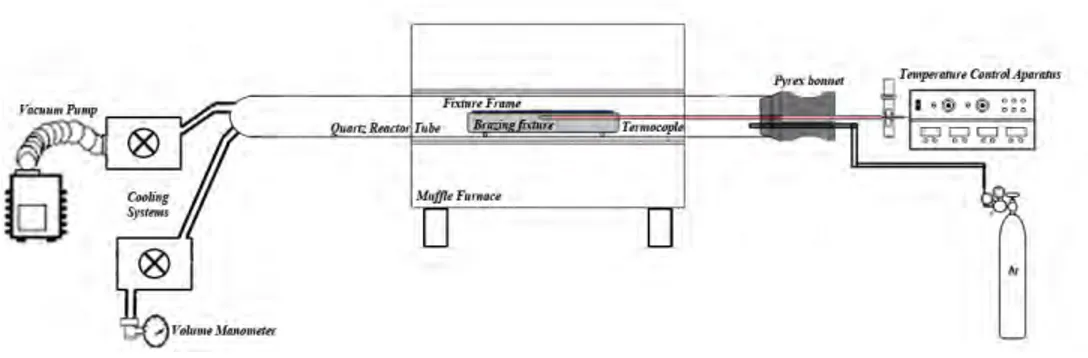
overlapped areas of the parent metals and carefully placed into an inert furnace. Schematic of inert furnace brazing (Iranian patent number: 72122) which used in this research is illustrated in Fig. 2. At first, the chamber was evacuated for about 10 min and then purged with high purity argon gas at a static flow which was controlled by volume manometer. Thermocouple (type K) connected to the samples proximity to the lap joint area. Heating in the furnace was achieved by heating a 2500 W high power furnace. Heating and cooling during the brazing cycles were carried out at 65 °C/min. The high cooling rate was achieved by introducing argon gas during the cooling part of the brazing cycle.
Symbol Designation Dimension (mm)
W1 Width of test piece 15
W2 Width of parallel part 10
L Length of test piece ~100
P Length of parallel part 20
T Thickness of test piece 1.5
R Radius of shoulder part 10 min
C Clearance 0.01 – 0..3
F Lap Length 3T
Fig. 1. Dimensions and assembly of brazed samples for shear test.
Fig. 2. Schematic of inert atmosphere furnace for brazing.
The ultrasonic test was carried out by using a probe of focusing type generating a longitudinal wave of 22 MHz in frequency. Measurements were performed on thickness measurement “Krautkramer Branson” according to AWS C3.8 [12] developed at the Iran air organization with a standard CL3 DL (Transducer: Alpha, Aerotech) which was attached to the surface of the brazed joint. Standard grinding and polishing
sample preparation procedure was applied [13] and Kroll’s reagent was used to evaluate the microstructures by light optical microscope. The cross-section of the brazed specimens was examined using a VEGA/TESCAN scanning electron microscope equipped with an energy dispersive spectrometer (EDS) for element distribution analysis. Equinox 3000 (Inel, France) X-ray diffractometer (XRD) was applied for fracture
analysis of selected furnace brazed specimens. The shear test was performed using a Zwick/Reoll Hct 400/25 dynamic testing machine with a constant crosshead speed of 0.5 mm/min. At least two shear test specimens were performed for each brazing condition. Failure analysis of the brazed specimen after the shear test was investigated using the SEM.
Results and discussion
Microstructure observations
According to ultrasonic testing, sound joint was obtained without any voids or cracks along joints which brazed at temperatures of 850°C and 870°C (samples brazed with CBS 34) and 870°C (samples brazed with STEMET 1228) as demonstrated in Table 1.
Table 1. Results of ultrasonic tests for brazed joints
Braze alloy (wt %) Temp. (◦C) Time (min) Layer Thickness (mm) Joint Thickness (mm) Results CBS 34 800 20 1.51 1.51 Rej. 850 10 1.5 3.05 Acc. 850 20 1.54 3.07 Acc. 870 10 1.5 3.11 Acc. 870 20 1.5 3.01 Acc. STEMET 1228 850 10 1.49 1.49 Rej. 850 20 1.5 1.5 Rej. 870 10 1.52 3.03 Acc. 870 20 1.45 3.09 Acc. 870 30 1.5 3.04 Acc.
According to Table 1, samples which brazed at 800°C with CBS 34 and 850°C with STEMET 1228 are rejected. Therefore, our study focused for accepted samples.
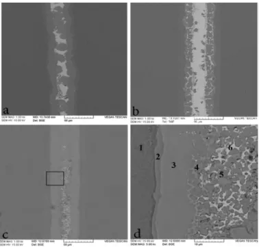
Fig. 3 shows SEM backscattered electron images (BEIs) of furnace brazed with STEMET 1228 at 870°C. Moreover, a quantitative overview of the chemical analysis (EDS) in atomic percent for different regions is provided in Table 2.
Fig. 3. SEM-BEIs of the brazed joints at 870 °C for 10 (a) and (b) 30 min with STEMET 1228
Table 2. Chemical analyses at regions shown in Fig. 3
Symbol Chemical analyses, at. %
Probable Phase
Ti Zr Ni Cu
1 93 2 2 3 α-Ti
2 87 5 3 5 (α-Ti ) + (Ti,Zr)2Ni + (Ti,Zr)2Cu
3 52 12 19 17 (Ti,Zr)Cu2, (Ti,Zr)2Ni,
(Ti,Zr)2Cu
I 80 12 5 3
Ti-Zr solid solution (rich in Cu and Ni)
II 83 10 4 3
III 70 20 8 2
This photograph denotes the microstructure has been uniform in element distribution when brazing time has increased. These characteristics are related to atomic diffusion phenomena such as isothermal solidification and solid-state diffusion during brazing [6, 14]. As a result of Fig. 3 (a), region 2 is a eutectoid microstructure containing Ti and a small amount of Ni, Cu and Zr are responsible for developing α-Ti with Ti2Ni and Ti2Cu. These phases should be the results
of the reaction of dissolving elements of base metal with Cu, Ni and Zr elements of the liquid filler metal. Region 3 is a central brazed layer which its composition is almost identical with that of the original filler metal. A primary crystal of Ti-Zr solid solution was formed at the filler metal side of the interface. As brazing time increased, filler metal layer (central region) disappeared and only a primary crystal and an aciculate microstructure were observed at the interface. This microstructure was formed by isothermal solidification, and caused diffusion of elements with lower melting point Zr, Cu and Ni into the base metal [15]. Similar microstructure was observed on the brazed joint with Zr-13.8Ti-10Ni-12.5Cu-22.5Be (at.%) alloy at 800°C for 10 min [6]. Consequently, brazing at 870°C, 30 min would promote formation of coarse acicular Widmanstätten structure.
Fig. 4 exhibits SEM BEIs and the EDS chemical analysis results of the Ti joints with CBS 34 brazing filler foil. Different layers of Ti-Cu intermetallic compounds appeared
between the brazed alloy and titanium substrate which their thickness increased after the brazing time or temperature had
been prolonged. According to layers chemical analysis illustrated in
Table 3 and the Cu–Ti and Ti-Ag phase diagrams shown in Fig. 5, titanium diffusion from titanium side toward the braze metal and diffusion of Ag and Cu from braze alloy to titanium substrate were the main controlling factor to build these intermetallic phases. As it is shown in
Fig. 4 (a, b), with increasing of temperature and time, the Ag solid solution matrix was contracted owing to the release of Cu to form more intermetallic phases with Ti.
Fig. 4 (c, d) shows interfacial reaction layers like β-Ti, Ti2Cu and TiCu formed at higher brazing time and were thick
which labeled with 1, 2 and 3 respectively. Formation of region 1 is owing to the solubility of Ag in α-Ti is much lower than that in β-Ti (Fig. 5a). Therefore, Ti2Cu and TiCu which
formed at higher brazing time, were thick and consumed most of the copper in the brazed zone. Also these phases are developed when Ti-CP vacuum brazed with Ag–27.2Cu– 12.5In–1.25Ti filler foil [9].
According to Zn-Cu phase diagram, solubility of Zn in Cu is 39-32.5 wt.% at temperature range of 454-902°C. Titanium and cadmium are proffered to solute in silver to form Ag solid solution matrix. Therefore by increasing temperature and time of brazing, these elements would dissolve in each other. afterwards excessive Ti and Zn atoms were expelled from Ag-matrix and generate intermetallic compounds like TiCu and Ti2Cu (labeled 4 and 5 in
Fig. 4d) but surrounded by silver and zinc solid solution matrix. Indeed, the shape of TiCu phase would change from continuous layer to globular particles with increasing of temperature or time. Region 6 is a poorer Ag-Zn solid solution matrix in contrast with region 5 which contain Ti2Cu
intermetallic compound.
Mechanical properties
Table 4 shows the mechanical properties of brazed specimens with various brazing conditions. The testing results revealed that shear strength of the specimens which brazed with STEMET 1228 at 870 °C increases with increasing brazing
Fig. 4. SEM BEIs of brazed joints: (a) 850 °C - 20 min; (b) 870 °C - 10 min; (c) 870 °C - 20 min and (d) closer view of
the rectangular area in (c) with CBS 34.
Table 3. Chemical analyses at regions shown in Fig. 4.
Symbol Chemical analyses, at. % Probable
Phase Ti Ag Cu Zn Cd 1 90 6.3 2 1.4 0.3 β-Ti 2 60.48 1.29 31 6.13 1.11 Ti2Cu 3 49.3 2.46 42.8 4.9 0.64 TiCu 4 22 39.2 22.5 13.9 2.42 TiCu rich in Ag-matrix 5 41.3 16.7 27.2 11.8 2.99 Ti2Cu rich in Ag-Zn matrix 6 42.3 12.8 25.5 14.8 1.67 Ti2Cu rich in Ag-matrix
Fig. 5. Binary alloy phase diagrams; (a) Ti–Ag, (b) Ti-Cu.
time, and the joints were fractured in the base metal for the brazing time of 30 min. However, increasing the brazing time or temperature led to more wetting, interaction or mutual diffusion at the interface which reflected high strength of the joint. From a microstructural point of view, the change of joint strength with the brazing parameters was to a large extent dependent on the joint microstructure. Therefore, it is concluded that brazed joint in this brazing condition has equal strength with base metal. However, as the brazing time has been lowered, the central brazed layer would remain in the brazed joint, and the brazed joints with low strength (186.2 MPa) were fractured in central brazed layer. These results have good agreement with furnace brazing of CP with Ti-37.5Zr-15Cu-10Ni as a filler alloy at 880°C, 30 min [10]. It was found from these results that the central brazed layer consisting of brittle intermetallic compounds, such as (Ti,Zr)Cu2, (Ti,Zr)2Ni and (Ti,Zr)2Cu, caused low shear
strengths of the joints. Therefore, to obtain the sufficient shear strengths for brazing Ti-CP with STEMET 1228, eliminating of the central brazed layer consisting of brittle intermetallic compounds is needed.
Shear strength of CBS 34 brazes joints revealed a general tendency to increase with an increase in holding time and brazing temperature. Best mechanical properties were achieved at a temperature of 870°C and at a holding time of 20
min where they were 164.2 MPa shear strength and 5.6% elongation. So, attained optimum shear strength is 63% of base metal. The maximum shear strength is approximately twice the strength reached by A. Elrefaey el at. [9]. The thickness and type of the reaction layer and intermetallic phases in between
the substrate and brazed alloy are critical factors in determining the strength of the joints. Titanium mainly reacted
with copper in all joints and formed almost the same kinds of Ti–Cu intermetallic phases. It is obvious in
Fig. 4 (a-d) that with an increase in brazing temperature or time, the thickness of layers increased. It is suggested that the shear strength of the joint was influenced by the formation of the required reaction layer to achieve good strength for the brazed joint. Increasing the temperature to 870°C led to an increase in the thickness of interaction layers, especially at a
holding time of 20 min. The main cause of increasing of shear strength and also elongation, belong to the nature of
microstructure (
Fig. 4d). Formation of hard intermetallic compound like TiCu and Ti2Cu in a ductile Ag-Zn solid solution matrix,
create a metal matrix composite which reinforced with TiCu and Ti2Cu. Indeed, These intermetallic compounds act as
second-phase particles which prevent moving of dislocation or slip planes. Small second-phase particles distributed in a ductile matrix are a common source of alloy strengthening. Furthermore, globular shape of these precipitations is another reason for increasing shear strength [16].
Finally, mechanical properties which were achieved from shear tests revealed that brazing of Ti-CP with STEMET 1228 has more strength in compare with brazing Ti-CP with CBS 34. Also, it was reported earlier by many researchers [4, 17, 18].
Table 4- Results of the shear tests for the samples brazed with STEMET 1228 and CBS 34 Braze alloy (wt %) Temp. (◦C) Time (min) average shear strength (MPa) Elongatio n (%) STEMET 1228 850 10 38.5 2 850 30 121 5.1 870 10 186.2 12 870 30 261.7 22 CBS 34 850 10 111 4.9 850 20 114.8 5 870 10 128 5 870 20 164.2 5.6
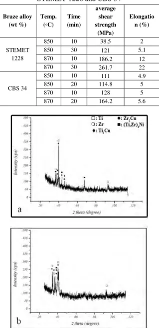
Fig. 6. XRD from fractured surfaces with STEMET 1228 at (a) 850°C, 20 min (a) and 870°C, 10 min (b).
Furthermore, to confirm the presence of different phases especially those directly at the fracture surface, XRD from fractured surfaces which brazed by STEMET 1228 at brazing
temperatures of 850 °C – 20 min and 870 °C - 10 min were analyzed as it is shown
Fig. 6. Several intermetallic compounds such as Ti2Cu, Zr2Cu
and (Ti,Zr)2Ni were detected and confirmed by XRD analysis
depending on the employed brazing parameters. According to Fig. 6b, peak intensity of the intermetallic phases (such as Ti2Cu) in specimen brazed at 870 °C – 10 min were lower than
the specimen brazed at 850 °C – 20 min (
Fig. 6a) which represented decline of this phases. Therefore lowering brittle intermetallic compounds such as Ti2Cu is
reason for increased joint strength. Hence, inordinate formation of brittle intermetallic phases (copper-based) was mainspring of fracture.
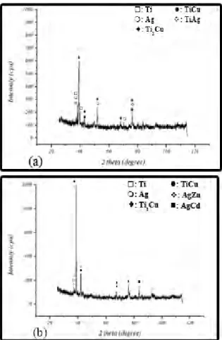
Fig. 7 shows the presence of Cu–Ti intermetallic compounds such as TiCu and Ti2Cu in an Ag-Zn solid solution
matrix at the fracture surface. For a specimen brazed at 850 °C – 20 min, TiCu brittle intermetallic phase was found at the fractured surface. The existence of Ti2Cu phase and Ag-Zn
solid solution matrix in the specimen brazed at 870 °C – 20 min leads to the occurrence of cleavage fracture instead of the brittle-dominated fracture type, as was observed in the specimen brazed at 850 °C.
Fig. 7. XRD from fractured surfaces with CBS 34 at brazing temperatures of 850°C (a) and 870°C (b) for 20 min
Conclusions
Commercially pure titanium has been successfully brazed using STEMET 1228 and CBS 34 in an inert gas furnace. The microstructural evolution and bonding strength were experimentally assessed. The conclusions are summarized as follows:
1- For the STEMET 1228 brazed specimen, Ti2Cu, Zr2Cu and
(Ti,Zr)2Ni interfacial reaction layer(s) are observed in the
brazed region. The furnace brazed joint at 870°C, 30 min demonstrates the highest average shear strength of 261.7 MPa, which was equal to strength of base metal. With increasing the brazing temperature and/or time, the average shear strength of the joint is increased due to excessive diffusion of alloying elements on filler to base metal and developing Widmanstätten microstructure.
2- For the CBS34 brazed specimen, Ag-rich matrix, interfacial Ti2Cu, TiCu and AgZn are found in the joint.
These phases were detected and confirmed by XRD analysis depending on the employed brazing parameters. The highest average shear strength was achieved at 870 °C, 20 min, which was about 164.2 MPa,
3- Excessive growth of interfacial TiCu and Ti2Cu phase in
brazed joint greatly deteriorates shear strength of the brazed joint.
4- In general, the shear strength of STEMET 1228 brazed joint is much higher than that of CBS34 brazed specimen.
Acknowledgements
The authors would like to appreciate the faculty of aerospace engineering, advanced materials and nanotechnology research laboratory of K.N.T.U and the air-line of Islamic republic of Iran (Iran Air) for cooperation and providing the experimental facilities. Also they are grateful to physical and mechanical properties laboratory faculty of biomedical engineering at AUT.
References:
[1] Donachie, M. j., TITANIUM: A Technical Guide, 2, (ASM, 2000). pp.
[2] Lutjering, G., et al., Titanium, 2, (Springer, 2007). pp. [3] Leyens, C., et al., Titanium and Titanium Alloys Fundamentals and Applications, (WILEY-VCH Verlag GmbH, 2003). pp.
[4] Shapiro, A. E., et al., "Brazing Of Titanium At Temperatures Below 800°C: Review And Prospective Applications," Proceedings of 8th International Conference in Brazing, High Temperature Brazing and Diffusion Welding, Aachen, Germany, 2007, pp. 254–267.
[5] Shapiro, A., et al., "State Of The Art Of Titanium-Based Brazing Filler Metals," Welding Journal Vol. (October 2003), pp. 36-43.
[6] Lee, J. G., et al., "Low-temperature brazing of titanium by the application of a Zr–Ti–Ni–Cu–Be bulk metallic glass (BMG) alloy as a filler," Intermetallics, Vol. 18, (2010), pp. 70–73.
[7] Schwartz, M. M., Brazing, 2 ed., (ASM, 2003). pp. 10-50. [8] Kang, D. H., et al., "Partially alloyed filler sheet for brazing of Ti and its alloys fabricated by spark plasma sintering method," Materials Science and Engineering A, Vol. 527, (2009), pp. 239–244.
[9] Elrefaey, A., et al., "Effect of brazing parameters on microstructure and mechanical properties of titanium joints," Journal of Materials Processing Technology, Vol. 209, (2009), pp. 4842–4849.
[10] Matsu, K., et al., "Titanium Brazing for Manufacturing Titanium Heat Exchangers," The Preliminary Program for 3rd International Brazing And Soldering Conference (IBSC), San Antonio, April 23-26, 2006, pp. 70-78.
[11] JISZ3192, "Methods for tension and shear tests for brazed joint," 1988
[12] AWSC3.8, "Recommended practice for ultrasonic inspection of brazed joints," 1997
[13] Metals Handbook, Vol 9: Metallography and Microstructures, (ASM, 1998). pp. 968-973.
[14] Hong, I. T., et al., "Microstructural evolution and shear strength of brazing C103 and Ti–6Al–4V using Ti–20Cu– 20Ni–20Zr (wt.%) filler metal," International Journal of Refractory Metals & Hard Materials, Vol. 24, (2006), pp. 247–252.
[15] Lee, J. G., et al., "Intermetallic formation in a Ti–Cu dissimilar joint brazed using a Zr-based amorphous alloy filler," Intermetallics, Vol. 18, (2010), pp. 529–535.
[16] Dieter, G. E., Mechnical Metallurgy, three, (Mc Graw hill, USA, 2001). pp. 295-310.
[17] MacDonald, W. D., et al., "Transient liquid phase bonding," Annual Reviews Material Science, Vol. 22, (1992), pp. 23-46.
[18] Huang, X., et al., "Activated Diffusion Brazing Technology for Manufacture of Titanium Honeycomb
Structures — A Statistical Study," Supplement To The Welding Journal, march 2004, pp. 73-81.