A New Signaling Scheme for Underwater Acoustic
Communications
Ahmad ElMoslimany
⇤, Meng Zhou
⇤, Tolga M. Duman
⇤†, Antonia Papandreou-Suppappola
⇤ ⇤Arizona State University, School of Electrical, Computer and Energy Engineering, Tempe, AZ 85287 †Bilkent University, Dept. of Electrical and Electronics Engineering, TR-06800, Bilkent, Ankara, TurkeyAbstract—Underwater Acoustic (UWA) communications has attracted a lot of interest in recent years motivated by a wide range of applications. Different signaling solutions have been developed to date including non-coherent communications, phase coherent systems, multi-input multi-output (MIMO) solutions and multi-carrier based approaches. In this paper, we develop a novel UWA communications paradigm using biomimetic signals. In our scheme, digital information is mapped to the parameters of a class of biomimetic signal set and at the receiver an estimator to obtain the parameter values is utilized. To facilitate this, we develop analytical signal models with nonlinear instantaneous frequencies matching mammalian sound signatures in the time-frequency plane. We provide suitable receiver structures, and present decoding results using data recorded during the Kauai Acomms MURI 2011 (KAM11) UWA communications experi-ment.
I. INTRODUCTION
Technological advances over the years have made UWA communications under a variety of settings, such as different depths or frequencies, a reality [1], [2]. These advances in technology happened due to the fact that in recent years UWA communications gained a lot of attention as their applications began to shift from military to commercial arena, e.g., remote control in off-shore oil industry, pollution monitoring in envi-ronmental systems, manned and unmanned oceanographic ex-ploration, dive rescue missions and diving safety, etc. Another application of interest is covert communications, where low probability of intercept (LPI) and low probability of detection (LPD) are desirable not only for military applications but for any application involving platforms that wish to communicate without disclosing their presence.
In covert UWA communications, we are interested in LPD and/or LPI which means that we seek to transmit our signals in such a way that the presence of communication cannot be sensed by eavesdroppers (LPD) and/or cannot be demodulated (LPI) except for the intended users. Most existing techniques developed for covert communications rely on spread spectrum ideas using direct sequence spread spectrum or frequency hopping techniques, see, for instance, [3]–[5]. A different approach to provide covertness is based on the use of natural sounds in transmission as in [6].
This work is funded by National Science Foundation under the contract NSF-ECCS 1102357 and by Office of Naval Research MURI Grant N00014-07-1-0739.
Many signaling and communications schemes have been developed for the underwater acoustic channels including MIMO solutions, multi-carrier based approaches and cooper-ative communications [7]–[9]. In this paper, we deviate from the traditional communication schemes, and propose a new communications paradigm that uses natural signals to transmit digital information. We develop analytical models for certain biomimetic signals and we parameterize them. Digital data is transmitted by mapping vectors of information bits to a carefully designed set of parameters with values obtained from the biomimetic signal modeling. To complete the overall system design, we develop appropriate receivers taking into account specific UWA channel models. The basic premise is the following: since there will be no artificial embedding of digital data on the host signal, the transmitted signal will non-invasively mimic a mammalian sound, thereby providing a way of information transmission as well as a means for true covert communications with LPD/LPI characteristics. In other words, signals matched to mammalian sounds, which are robust to environmental changes, could be used for covert UWA communications at relatively high transmit power levels, i.e., high signal-to-noise ratios (SNRs). They can also co-exist with other acoustic communication systems without adversely affecting their performance or without being affected by them. The paper is organized as follows. In Section II, we develop analytical models for certain class of biomimetic signals and provide a parametrization for these models. In Section III, we describe the proposed communication paradigm, i.e., the signaling scheme and the corresponding receiver structure. In Section IV, we present a set of results demonstrating feasibility of the proposed communications scheme using data recorded in the recent KAM11 experiment.
II. BIOMIMETICSIGNALMODELING
Cetacean mammals, such as dolphins and whales, have com-plicated communication systems. Their sound emissions are mainly classified into clicks and whistles [10], [11]. The time-frequency variations of dolphin and whale whistles inspire us to model their biological sounds and use the resulting models to design transmit waveforms for underwater communications. In [12], dolphin and whale whistle sounds were analyzed using quadratic time-frequency representations (QTFRs). Based on this analysis, the time-frequency structure of whistle sounds was modeled to match the instantaneous frequency of
eralized frequency-modulated signals. We thus want to use these biomimetic signal models, with parameters and nonlinear instantaneous frequency characteristics that match those of real whistle sounds, for underwater acoustic communications. A. Generalized Frequency-Modulated Signals
Generalized frequency-modulated (GFM) signals are de-fined as [13]
s(t; b) = A↵(t)ej2⇡(c⇠(t/tr)+f0t), 0 < t T
d, (1) where ⇠(t/tr)is the signal’s phase function, f0 is the carrier frequency, A is the amplitude, c 2 IR is the frequency modulation (FM) rate and tris a positive reference time. The vector b can be defined to include GFM parameters such as the FM rate c, the signal duration Td, the amplitude A and the phase function ⇠(t/tr).
B. Biomimetic Signal Matching
By varying the phase function ⇠(t/tr) in (1), we can obtain different instantaneous frequencies ⌫(t) that can be used to match various time-frequency structures of the cetacean mammal whistles. Table I provides some examples of GFM signals from (1) with tr = 1, together with their phase functions ⇠(t/tr)and corresponding instantaneous frequencies ⌫(t).
GFM Signal Phase Functionc ⇠(t/t
r) Instantaneous Frequency c ⌫(t) Linear c t2 2c t Hyperbolic c ln t c/t Logarithmic c t(ln t 1) c ln t Power c t c t 1 Exponential c et c et TABLE I
GFMSIGNALS IN(1)WITH CORRESPONDING NONLINEAR PHASE
FUNCTIONS AND INSTANTANEOUS FREQUENCIES.
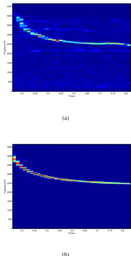
In order to demonstrate the biomimetic modeling perfor-mance, we analyze the actual whale whistles as an example, together with our reconstructed signals using the GFM model in (1). The whistle sounds are obtained from the SOUND database of W. A. Watkins from the Woods Hole Oceano-graphic Institution [14]. Fig. 1 compares the spectrogram QTFR of an actual long-finned pilot whale whistle and its reconstructed GFM signal with tr = 1. As the instantaneous frequency of the signal decreases monotonically in Fig. II-B, we reconstruct it using the hyperbolic FM signal in Fig. II-B with instantaneous frequency c ⌫(t) = c/t in Table I. As it can be seen, the time-frequency structure of the whistle and the reconstructed signal is well-matched.
Now that models for the mammalian sounds are developed along with appropriate parameterization. We can turn our attention to the proposed communications system exploiting these sounds. Time/s Frequency/Hz 0.4 0.45 0.5 0.55 0.6 0.65 0.7 0.75 0.8 0 500 1000 1500 2000 2500 3000 3500 4000 4500 (a) Time/s Frequency/Hz 0.4 0.45 0.5 0.55 0.6 0.65 0.7 0.75 0.8 0 500 1000 1500 2000 2500 3000 3500 4000 4500 (b)
Fig. 1. Spectrogram QTFRs: (a) long-finned pilot whale whistle; (b) reconstructed noiseless linear FM chirp signal that best matches the time-frequency signature of the whistle.
III. A NOVELCOMMUNICATIONPARADIGM
We develop a signaling scheme that uses biomimetic signals such as the ones studied in the previous section, as the transmission signals that carry digital data. We modulate the parameters of these biomimetic signals with the transmitted bits, transmit it over the UWA channel, and estimate these parameters at the receiver to decode for the transmitted bits.
As we see from (1), we can use amplitude, carrier frequency, chirp rate, and chirp duration as the parameters that carry our bitstream. At the receiver side, we develop a maximum likelihood estimator (MLE) to estimate the values of these parameters and decode for the transmitted bits. To summarize, we have a set of signals with a set of parameters C and an information sequence I. The transmitter maps the information sequence I to a vector b using a certain mapping function f (I) where the elements of the vector b are picked from the set C. Then, a continuous-time waveform s(t; b) is generated and transmitted over the channel. At the receiver side, we develop a detector to find an estimate ˆb of the values of these signal parameters using MLE. Finally, a demapping function
f 1(ˆb) is used to restore the transmitted bits. A. Receiver Design for AWGN Channels
In this section, we consider the use of the proposed com-munication scheme over an additive white Gaussian noise (AWGN) channel. We develop the ML estimates of the signal parameters for the Gaussian channel and we characterize its performance.
The discrete time version of a real generalized chirp is defined as
s[n] = Ap⌫[n] cos (2⇡c⇠[n]) , n = 0, 1, . . . , M 1, (2) where A is the amplitude of the signal, c is the generalized chirp parameter that controls the shape of the instantaneous frequency, ⇠[n] is the discrete version of the frequency mod-ulation function ⇠(t), and ⌫[n] is the discrete version of the instantaneous frequency ⌫(t) = d
dt⇠(t). The received signal can be written as,
x[n] = (
s[n] + w[n] if n = 0, 1, . . . , M 1, w[n] if n = M, . . . , N 1, (3) where w[n] is the AWGN with zero mean and variance 2.
The conditional PDF of the received signal x[n] defined in (3) is given by, p(x; ) = 1 (2⇡ 2)N2 exp " PM 1 n=0 (x[n] s[n])2 PN 1 n=Mx2[n] 2 2 # .
Thus, the MLE [15] of the vector of parameters = [A c M ]T is given by, 2 4 ˆ c ˆ M ˆ A 3 5 = arg min c,M,A (M 1 X n=0 (x[n] s[n])2+ NX1 n=M (x[n])2 ) ,
which can be reformulated as
2 4 ˆ c ˆ M ˆ A 3 5 = arg min M 8 > > > > > < > > > > > : min c,A MX1 n=0 x[n] s[n])2 | {z }
separate optimization problem
+ NX1 n=M (x[n])2 9 > > > > > = > > > > > ; .
That is, we can separate the problem into two sub-problems where one is optimization over the chirp duration and the other is optimization over the other parameters (the chirp rate c and amplitude A), for a specific chirp duration.
For a given chirp duration ˆM, we define r[n] = p
⌫[n] cos (2⇡c⇠[n]) , n = 0, . . . , ˆM 1, and the vector of parameters ✓ = [A c]T
The cost function g(A, c; ˆM )to be minimized is then g(A, c; ˆM ) =
ˆ MX1
n=0
(x[n] Ar[n])2. (4) Thus, the maximum likelihood estimation problem reduces to
ˆ
✓ = arg min
c,A g(A, c; ˆM ). (5)
To estimate the parameters A and c we need to do a two-dimensional grid search over the given range of both parame-ters. However, this two-dimensional search can be reduced to a one-dimensional search as we are able to find a closed form expression for the optimal amplitude estimator for any given value of c. That is, given c, the optimal amplitude value can be found by minimizing the cost function resulting in
ˆ A = PMˆ 1 n=0 x[n]r[n] PMˆ 1 n=0 r2[n] . (6)
Let us now comment on the asymptotic behavior of the MLE for the parameters A and c. Under certain regularity conditions [16, p. 183], the maximum likelihood estimator has asymptotically (as the number of samples becomes large) a Gaussian distribution with mean being the true mean and co-variance matrix given by the inverse of the Fisher information matrix [15]. The regularity conditions include the following: the true parameter value must be interior to the parameter space, the log-likelihood function must be twice differentiable, the second derivatives must be bounded, the expected value of the log-likelihood function equals zero when the values of the parameters are taken as the true values. It is straightforward to show that the MLE of the vector ✓ in our case satisfies these conditions, and hence for large number of samples, the estimated vector of parameters ˆ✓ has approximately a Gaussian distribution, i.e.,
ˆ
✓⇠ N ✓, I(✓) 1 , (7)
where N (µ, C) denotes a Gaussian distribution with mean vector µ and covariance matrix C, and I(·) is the Fisher information matrix.
B. Receiver Design for Multipath Dispersive Channel We now consider transmission over a time dispersive chan-nel which is typical in UWA communications. We use the same transmitted signal as in (2), then the discrete time received signal can be written as
x[n] =
(PL 1
l=0 hl[n]s[n l] + w[n] if n = 0, 1, . . . , M 1,
w[n] if n = M, . . . , N 1,
(8) where w[n] is an AWGN, and hl[n]is the time varying channel coefficient at the lth delay pin and the nth instant. We assume that the receiver has an estimate for these channel coefficients. Following a similar approach as in the previous subsection, given a certain value for the signal duration (the length of the signal is estimated via a grid search), we perform a one-dimensional grid search (over the parameter c) instead of the two-dimensional grid search (over the two parameters A and c). That is because we are able to find the optimal estimator for the amplitude given the value of c in closed form, that is,
ˆ A = PMˆ 1 n=0 x[n]u[n] PMˆ 1 n=0 u2[n] , (9)
where u[n] = PL 1
l=0 hl[n]r[n l], n = 0, . . . , M 1, and r[n] is as defined before.
In practice, the receiver structure for the proposed commu-nication system over a multipath dispersive channel consists of two main blocks; a channel estimator and an MLE. The chan-nel estimator feeds the MLE with the chanchan-nel estimates that will be used in maximizing the likelihood function. To estimate the channel coefficients we use one of the common channel estimation techniques for UWA channels, e.g., the matching pursuit (MP) [17] or basis pursuit (BP) [18] algorithms.
As in the previous subsection, it can be shown that the asymptotic distribution of the ML estimated vector ˆ✓ is (asymptotically) Gaussian with mean equal to the true mean and covariance matrix given by the inverse of the Fisher information matrix, i.e.,
ˆ
✓⇠ N ✓, I(✓) 1 . (10)
IV. EXPERIMENTALRESULTS
We now provide some experimental results for the proposed communication system based on measurements taken at the recent KAM11 experiment [19].
A. KAM11 Experiment
The KAM11 experiment was conducted in shallow water off the western coast of Kauai, Hawaii, at the Pacific Missile Range Facility (PMRF) during the period 23 June and 12 July 2011. We consider a fixed-source scenario for which there is no intentional motion between the transmitter and the receiver. An 8-element vertical-array source was deployed with an inter-element separation of 7.5m and an aperture of 52.5m. The top element was at a nominal depth of 30m, and the bottom element was not anchored to the sea floor. At the receiver side, a 16-element vertical array was deployed at a distance of 4km from the source. The inter-element spacing was 3.75m, with the top element deployed at a nominal depth of 35.5m.
The transmitted signal during the KAM11 experiment is a linear phase chirp signal x(t), given by
x(t) = A cos 2⇡f0t + 2⇡ct2 , 0 < t < T (11) where A is the amplitude of the chirp signal, f0 is the center frequency, c is the chirp rate, and T is the signal duration. The amplitude was varied between 0.5 and 1; the center frequency was between 22kHz and 26kHz; the chirp rate was changed between 2kHz and 10kHz, and the signal duration was selected from 100ms to 200ms. We use the linear frequency modulated chirps (instead of true biological sounds) for the sake of illustrating the methodology and showing the validity of the proposed communications scheme.
Every recoding consists of seven transmission frames (sometimes, called subgroups) where each subgroup corre-sponds to a different transmission rate. Different data rates are attained from the fact that we map each parameter to different number of bits, e.g., in the first subgroup the parameters are mapped to four bits, in the second subgroup the parameters are mapped to five bits, etc. In each subgroup, we transmit 30
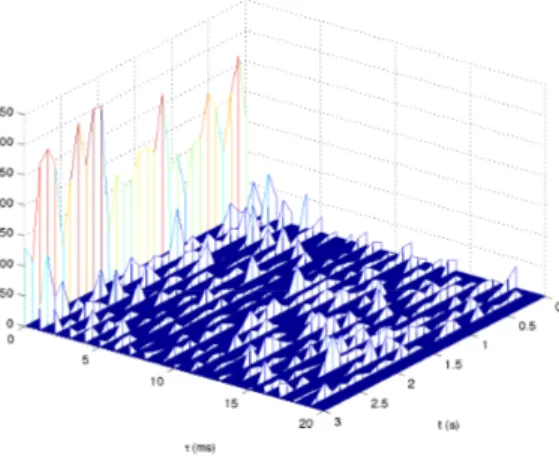
Fig. 2. Channel impulse respose for 30 consecuitive chirps at the first receive element in the first enviroment, this estimates have been computed from the data recorded on July 2nd, 2011 at 3:24.
consecutive chirp samples separated by a 60ms guard period. Thus, the transmission rates that correspond to these subgroups are 107 bits per second (bps), 127bps, 147bps, 167bps, 187bps, 207bps, and 227bps, respectively.
B. Channel Estimation
For channel estimation purposes, we use the transmitted chirp signals as the channel probes as well. We employ the MP algorithm [20] to find an estimate of the channel coefficients. The main issue in using the chirp signals in estimating the channel is their poor auto-correlation properties. Since the auto-correlation function of chirp signals is not close to an impulse, a resolution issue appears in the channel estimation process as we cannot resolve all the arrivals that lie in a certain time interval. This implies that we cannot use a dictionary with a high resolution, and we have to settle for coarse channel estimates.
For the MP algorithm we use a dictionary that allows us to resolve only channel taps with a 1ms separation and we limit the maximum delay spread of the estimated channel to be 20ms. As an example, Fig. 2 shows the time varying channel impulse response which is computed over a duration which is equal to the duration spanned by 30 adjacent chirp signals. C. Decoding Results
The receiver has 16 receive elements, therefore it is possible to use receive diversity to enhance the performance of the system. To accomplish this different combining techniques can be deployed at the receiver, for instance, majority voting (MV) technique, or the selection combining. Here, we only focus on the results of the MV combining technique, i.e., the final decision is made by the majority voting rule. In other words, the final decision is said to be “1”(“0”) if more than half of the receive elements decide for “1”(“0”).
We now present bit error rate results for the proposed com-munications scheme. At the receiver, a chirp signal block is used to estimate the channel coefficients; then these estimated
0 5 10 15 20 0 0.5 1 1.5 2 2.5 3 3.5 4 4.5 frame index BEP (%)
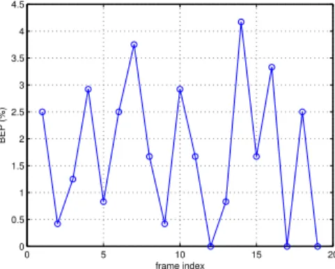
Fig. 3. The uncoded error probability of the chirp parameters at rate equals to 107bps, the table shows the uncoded BEP resulted from using majority voting combining technique.
R (bps) 107 127 147 167 187 207 227 Env1 1.7% 3.7% 2.2% 1.7% 5.6% 8.2% 13.5% Env2 0% 0% 1.9% 2.9% 4.4% 8.3% 11.7% Env3 0% 2% 1.1% 0.7% 6.5% 7.4% 13% Env4 2.5% 7% 1.1% 1.9% 7.7% 8.3% 13.5% TABLE II
ERROR PROBABILITY FOR DIFFERENT TRANSMISSION RATES USING THE
MVCOMBINING TECHNIQUE.
channel coefficients are used to decode the next block, and so on. We can justify this from Fig. 2 which shows that the channel impulse responses separated by a chirp duration are close to each other and the channel does not change significantly from one signal block to the other. Fig. 3 shows the uncoded error probability results for nineteen different recordings using the majority voting combining technique. The results correspond to a transmission rate of 107bps. These recordings were taken at different time instances during the experiment. As another example, Table II shows the error probability for different transmission rates using the same combining technique. The decoding results clearly demon-strate the feasibility of the proposed communications paradigm which is expected to be beneficial, particularly, for LPI/LPD applications.
V. CONCLUSIONS
In this paper, we proposed a novel UWA communications paradigm using biomimetic signals as the communication signals where we modulate the parameters of the sound signal with information bits. We first developed analytical signal models with nonlinear instantaneous frequencies matching mammalian sound signatures in the time-frequency plane. Then, we parametrized the resulting signal model, and use these parameters to carry information bits. At the receiver side, we designed an estimator to obtain the parameters of the transmitted signal, and demapped the estimated values to information bits. We also demonstrated the viability of the proposed communication scheme via experimental results recorded at the recent KAM11 experiment.
REFERENCES
[1] R. F. W. Coates, Underwater acoustic systems. Halsted Press, 1989. [2] X. Lurton, Underwater acoustics: an introduction. Springer, 2002. [3] J. Ling, H. He, J. Li, W. Roberts, and P. Stoica, “Covert underwater
acoustic communications: Transceiver structures, waveform designs and associated performances,” in IEEE OCEANS, 2010, pp. 1–10. [4] T. Yang and W.-B. Yang, “Low signal-to-noise-ratio underwater
acous-tic communications using direct-sequence spread-spectrum signals,” in IEEE OCEANS, 2007, pp. 1–6.
[5] G. Leus and P. van Walree, “Multiband OFDM for covert acoustic communications,” IEEE Journal on Selected Areas in Communications, vol. 26, no. 9, pp. 1662–1673, 2008.
[6] J. Severson, “Modeling and frequency tracking of marine mammal whistle calls,” Master’s thesis, Massachusetts Institute of Technology, 2009.
[7] S. Roy, T. Duman, V. McDonald, and J. Proakis, “High-rate communi-cation for underwater acoustic channels using multiple transmitters and space-time coding: Receiver structures and experimental results,” IEEE Journal of Oceanic Engineering, vol. 32, no. 3, pp. 663–688, July 2007. [8] Y. Emre, V. Kandasamy, T. M. Duman, P. Hursky, and S. Roy, “Multi-input multi-output OFDM for shallow-water UWA communications (invited paper),” in Proceedings of ACOUSTICS 2008, July 2008. [9] S. Al-Dharrab, M. Uysal, and T. M. Duman, “Cooperative underwater
acoustic communications,” IEEE Communications Magazine, pp. 146– 153, July 2013.
[10] W. W. L. Au, The Sonar of Dolphins. Springer-Verlag, 1993. [11] J. E. Reynolds III and S. A. Rommel, Eds., Biology of Marine Mammals.
Washington D. C.: Smithsonian Institution Press, 1999.
[12] A. Papandreou-Suppappola, “Biological signal analysis, detection, and estimation,” Naval Undersea Warfare Center, Newport, RI, Tech. Rep. 11284, Dec. 2001.
[13] ——, “Generalized time-shift covariant quadratic time-frequency rep-resentations with arbitrary group delays,” in Asilomar Conference on Signals, Systems and Computers,, Pacific Grove, CA, Oct. 1995, pp. 553–557.
[14] W. A. Watkins, K. Fristrup, M. A. Daher, and T. Howald, “SOUND database of marine animal vocalizations structure and operations,” Woods Hole Oceanographic Institute, Woods Hole, MA, Tech. Rep. WHOI-92-31, Aug. 1992.
[15] S. Kay, Fundamentals of statistical signal processing: Estimation theory. Prentice-Hall, 1993.
[16] H. V. Poor, “An introduction to signal detection and estimation,” New York, Springer-Verlag, vol. 1, 1988.
[17] W. Li and J. C. Preisig, “Estimation of rapidly time-varying sparse channels,” IEEE Journal of Oceanic Engineering, vol. 32, no. 4, pp. 927–939, 2007.
[18] S. J. Wright, R. D. Nowak, and M. A. T. Figueiredo, “Sparse recon-struction by separable approximation,” IEEE Transactions on Signal Processing, vol. 57, no. 7, pp. 2479–2493, 2009.
[19] W. S. Hodgkiss, H. C. Song, G. Dean, M. Badiey, and A. Song, “Kauai Acomms MURI 2011 (KAM11) Experiment Trip Report,” Technical Report, Tech. Rep., 2011.
[20] C. R. Berger, S. Zhou, J. C. Preisig, and P. Willett, “Sparse channel estimation for multicarrier underwater acoustic communication: From subspace methods to compressed sensing,” IEEE Transactions on Signal Processing, vol. 58, no. 3, pp. 1708–1721, 2010.