Tarım Bilimleri Dergisi
Tar. Bil. Der.Dergi web sayfası:
www.agri.ankara.edu.tr/dergi
Journal of Agricultural Sciences
Journal homepage:
www.agri.ankara.edu.tr/journal
TARIM BİLİMLERİ DERGİSİ
—
JOURNAL OF AGRICUL
TURAL SCIENCES
21 (2015) 459-470
Experimental Investigation of Various Type Absorber Plates for Solar
Air Heaters
Nuri ÇAĞLAYANa, Zeliha Deniz ALTAb, Can ERTEKİNb
aAkdeniz University, Faculty of Engineering, Department of Mechatronics Engineering, Campus, 07058, Antalya, TURKEY bAkdeniz University, Faculty of Agriculture, Department of Agricultural Machinery, Campus, 07058, Antalya, TURKEY ARTICLE INFO
Research Article
Corresponding Author: Nuri ÇAĞLAYAN, E-mail: [email protected], Tel: +90 (242) 310 60 16 Received: 18 April 2014, Received in Revised Form: 22 August 2014, Accepted: 29 September 2014
ABSTRACT
In this study, four different types’ absorber plates were designed and compared of their energetic performances. These absorber plates were formed as a flat plate (Type I), V-shaped (Type II), wedge-shaped (Type III) and wavy-shaped (Type IV). Each type absorber plate was manufactured in both aluminum (Al) and copper (Cu) materials. Energy efficiencies of the heaters were investigated with airflow velocities of 2, 3 and 4 m s-1 experimentally and compared with each other. The results showed that efficiency of the heater with the copper absorber plate better than aluminum plate however, the resulting air temperature from heater with aluminum absorber plate higher than cooper plate. The experimental results have shown that Type IV and Type II achieved the highest energy efficiency, respectively.
Keywords: Solar air heater; Absorber plate; Airflow velocity; Energy efficiency
Hava Isıtıcılı Güneş Kollektörleri İçin Farklı Tip Yutucu Plakaların
Deneysel İncelenmesi
ESER BİLGİSİ
Araştırma Makalesi
Sorumlu Yazar: Nuri ÇAĞLAYAN, E-posta: [email protected], Tel: +90 (242) 310 60 16 Geliş Tarihi: 18 Nisan 2014, Düzeltmelerin Gelişi: 22 Ağustos 2014, Kabul: 29 Eylül 2014
ÖZET
Bu çalışmada hava ısıtıcı kollektörler için dört farklı tip yutucu plaka tasarlanmış ve bunların enerjik performansları karşılaştırılmıştır. Bu yutucular, düz (Tip I), V (Tip II), trapez (Tip III) ve dalga (Tip IV) şeklindeki plakalardan oluşmaktadır. Her tip yutucu hem alüminyum (Al) hem de bakırdan (Cu) imal edilmiştir. Isıtıcıların enerji verimleri 2, 3 ve 4 m s-1 hava hızında deneysel olarak incelenmiş ve karşılaştırılmıştır. Elde edilen sonuçlara göre, bakır yutucu plakalı ısıtıcının, alüminyum yutucu plakalıdan daha verimli olduğu, ancak alüminyum yutucu plakalı ısıtıcının çıkış hava sıcaklığının bakır plakalıdan daha sıcak olduğu görülmüştür. Deneysel sonuçlara göre en yüksek enerji verimleri sırasıyla IV.ve II. Tip yutucu plakalı ısıtıcılarda elde edilmiştir.
Anahtar Kelimeler: Hava ısıtmalı kollektör; Yutucu plaka; Hava akış hızı; Enerji verimi
Experimental Investigation of Various Type Absorber Plates for Solar Air Heaters, Çağlayan et al
460
Ta r ı m B i l i m l e r i D e r g i s i – J o u r n a l o f A g r i c u l t u r a l S c i e n c e s 21 (2015) 459-4701. Introduction
The use of solar air heater has been increasing in
recent years, because of their simplicity, cheapness,
ease of their maintenance and operation, friendly for
environment and non-fuel operation. Such heaters
are implemented in many applications that require
low to moderate temperature below 60 °C (Gupta &
Kaushik 2008).
In agricultural area, the main application of solar
air heater is drying by means of solar drying. Using
a solar dryer, the drying time can be shortened by
about 65% compared to natural sun drying because,
inside the dryer, it is warmer than outside; the
quality of the dried products can be improved in
terms of hygiene, cleanliness, safe moisture content,
color and taste; the product is also completely
protected from rain, dust, insects, rodents; and its
payback period ranges from 2 to 4 years depending
on the rate of utilization (Eliçin & Saçılık 2005).
The quality of dried product is mostly dependent
on drying air temperature, velocity and drying
time (Aktaş et al 2012; Tülek & Demiray 2014).
On the other hand, the thermal efficiency of solar
air heater has been found to be poor due to the low
heat transfer capacity and low heat conductivity of
air. Therefore, several researchers have studied to
design several types of solar air heaters to improve
their performance (Youcef-Ali 2005; Kurtbaş &
Turgut 2006; Gao et al 2007; Esen 2008; Varol &
Öztop 2008; Luna et al 2010).
Ayadi et al (2014) investigated the performance
of two components of a solar drying unit (collector
and storage system) without drying energy
supplement. They used a V-corrugated absorber
and single glazing in the air collector and metal
parallelepiped system for storage unit. According
to their experimental results, average collector
efficiency and outlet temperature were found as
30.52% and 54.06 °C, respectively.
Karim & Hawlader (2006) presented a
performance study on V-groove solar air collector
for drying application and V-corrugated collector
was found better thermal efficiency (about 12%
more efficiency) compared to flat plate collector. In
their study the height of the ‘V’ and the dimensions
of absorber plate were selected as 10 cm and 1.8
m x 0.7 m, respectively. Absorber material was
black-painted mild steel and the number of glazing
was one. Karim et al (2012) also developed a
mathematical model for this type collector and
compared the simulation results carried out using
MATLAB with experimental study.
Ho et al (2011) investigated the collector
efficiency of upward-type double-pass flat plate
solar air heaters with fins attached and external
recycle theoretically. Collector efficiency increases
as airflow rate, number of fins attached and incident
solar radiation increase. Considerable improvement
in collector efficiency is also obtainable if the
operation is carried out with external recycling.
Ben-Amara et al (2005) presented experimental
results of a new-design plate collector used to
heat air in a new desalination humidification–
dehumidification process. In addition, the effects
of different parameters on the collector efficiency,
such as solar radiation, wind velocity, ambient
temperature, air mass flow rate, air temperature and
humidity through the collector was investigated.
Kurtbaş & Durmuş (2004) investigated the effect
of airflow line on the performance of solar collectors
with absorber slices having four different surface
geometries. The efficiency of collectors increases
depending on the collector surface geometry and
extension of the airflow line. As a result, it appears
that if the surface roughness is increased, the heat
transfer and pressure loss increases.
Karslı (2007) determined the first and second
law efficiencies of four types of air heating flat plate
solar collectors; finned with an angle of 75°, finned
with an angle of 70°, with tubes and a base collector.
As a result, the highest energy efficiency (80%) and
air temperature rise were found for the collector
finned with angle of 75°, whereas the lowest values
were obtained for the base collector.
Mittal et al (2007) compared effective efficiency
of a solar collector with different geometry type
having roughness elements on the absorber
plate. In this study, the relative roughness height
Hava Isıtıcılı Güneş Kollektörleri İçin Farklı Tip Yutucu Plakaların Deneysel İncelenmesi, Çağlayan et al
461
Ta r ı m B i l i m l e r i D e r g i s i – J o u r n a l o f A g r i c u l t u r a l S c i e n c e s 21 (2015) 459-470
is considered as strong parameter of roughness
element for effective efficiency of solar collector. It
is observed that among all the roughness elements
investigated, the inclined ribs having low values
of roughness height resulted in better effective
efficiency in higher range of Reynolds number
(more than 12000). However, in lower range of
Reynolds number (less than 12000), the better
effective efficiency is observed for the solar air
heaters having expanded metal mesh as artificial
roughness element. Further, it is observed also that
the effective efficiency of solar air heater is better
than the roughened solar air heaters in the range of
very high Reynolds number.
Karwa & Chauhan (2010) presents results of the
performance of solar air heater with 60° v-down
discrete rectangular cross-section repeated rib
roughness on the airflow side of the absorber plate.
The effects of various ambient, operation and design
parameters on the thermal and effective efficiencies
of air heaters have been investigated. The study
shows that, at air mass flow rates less than about
0.04 kg s
-1m
-2of the absorber plate, roughened duct
solar air heaters provide significant performance
advantage over the smooth ducted solar air heater.
At the mass flow rate of about 0.045 kg s
-1m
-2, the
effective efficiencies of the roughened and smooth
duct solar air heaters are practically the same.
Alta et al (2010) investigated the effects of
the mass flow rate (25, 50 and 100 m
3m
-2h
-1) and
title angle (0°, 15° and 30°) on the efficiencies
of different types of designed flat-plate solar air
heaters. It was found that attaching fins on absorber
surface increases the efficiency of solar air heater.
The energy efficiency of the heater also improved
with increasing airflow rates due to an enhanced heat
transfer to the airflow while temperature difference
of fluid decreases at constant tilt angle.
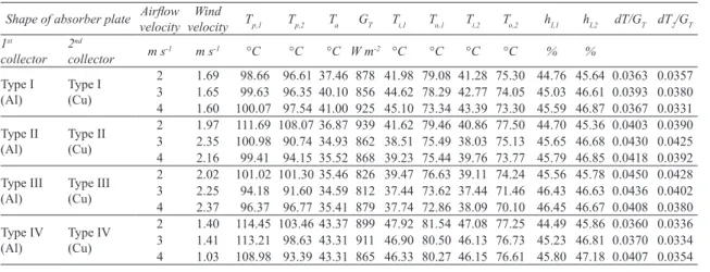
This paper presents a comparison of energy
efficiencies of solar air heaters having plates
with four different geometry types, two different
materials (Al and Cu) and for 2, 3 and 4 m s
-1airflow velocities. Comparisons of the energetic
and economic advantages of the collectors with
absorber plate in different dimensions, geometries
and materials are distinctive properties of this study.
2. Material and Methods
2.1. Experimental setup and measurement
procedure
In the study, two experimental solar collectors
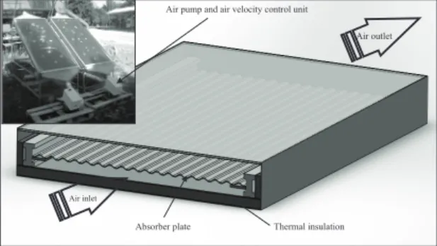
were used and mounted as shown in Figure 1. A
single glazing was chosen in order to maximize
the radiation impact on the absorber. Dimension
of the collectors are 1.92 x 0.82 x 0.10 m and they
have insulation thickness of 0.05 m in the bottom
and sides. The gap between the absorber plate
and bottom is 0.043 m. Al and Cu absorber plates
thickness of 2 mm and their surfaces are painted
matt black. All plates are designed as a portable.
3
the energetic and economic advantages of the collectors with absorber plate in different dimensions, geometries and materials are distinctive properties of this study.
2. Material and Methods
2.1. Experimental setup and measurement procedure
In the study, two experimental solar collectors were used and mounted as shown in Figure 1. A single glazing was chosen in order to maximize the radiation impact on the absorber. Dimension of the collectors are 1.92 x 0.82 x 0.10 m and they have insulation thickness of 0.05 m in the bottom and sides. The gap between the absorber plate and bottom is 0.043 m. Al and Cu absorber plates thickness of 2 mm and their surfaces are painted matt black. All plates are designed as a portable.
Figure 1- The experimental solar air heater
Şekil 1- Deneysel hava ısıtmalı güneş kollektörü
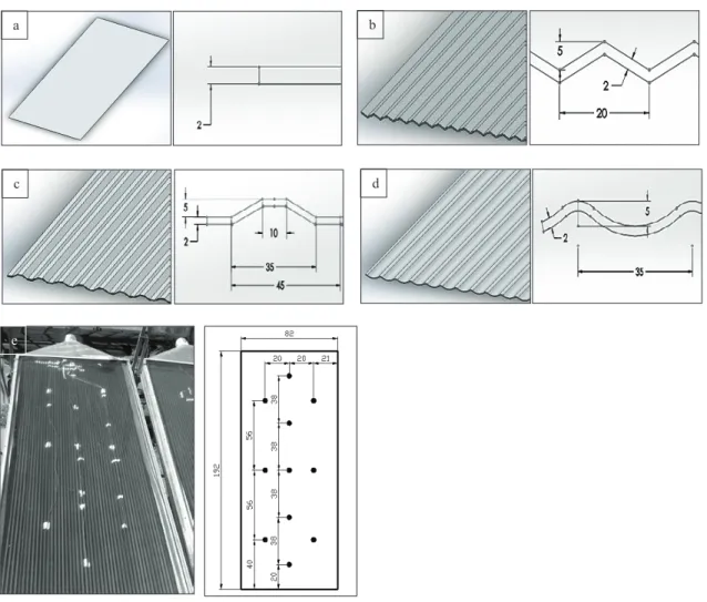
The schematic diagrams and cross-sections of the absorber types are presented in Figure 2. The surface areas of collectors are 1.5744, 1.7602, 1.6412 and 1.6284 m2and the airflow areas are 0.033616, 0.033426, 0.033550, 0.033558 m2, respectively.
Thermal insulation
Air inlet
Air outlet
Absorber plate
Air pump and air velocity control unit
Figure 1- The experimental solar air heater
Şekil 1- Deneysel hava ısıtmalı güneş kollektörü
The schematic diagrams and cross-sections of
the absorber types are presented in Figure 2. The
surface areas of collectors are 1.5744, 1.7602, 1.6412
and 1.6284 m
2and the airflow areas are 0.033616,
0.033426, 0.033550, 0.033558 m
2, respectively.
In this study, collector inlet and outlet air
temperature, ambient temperature, airflow rate,
solar radiation, pressure drop and wind velocity
was measured and all of data recorded by a data
logger. A radial fan with a capacity of 0.41 m
3s
-1was used for each collector to provide the airflow.
The fan speed and airflow rate can be adjusted by an
electrical controller unit.
Experimental Investigation of Various Type Absorber Plates for Solar Air Heaters, Çağlayan et al
462
Ta r ı m B i l i m l e r i D e r g i s i – J o u r n a l o f A g r i c u l t u r a l S c i e n c e s 21 (2015) 459-470Inlet and outlet air temperature, absorber
surface and ambient temperature were measured
using K-type thermocouples. Wind velocity was
measured using a cup anemometer (Delta-T A100
R model, accuracy: 1% ± 0.1 m s
-1). Anemometer
was placed about 1 m above the collector. A flow
meter (Testo 405, accuracies: ± 0.1 m s
-1± 5% of
m.v. at 0-2 m s
-1) was used to measure the air inlet
velocity for the solar collector. Incident radiation on
the collector was measured using a global radiation
sensor (Delta-T ES2 accuracy: ±3% at 20 °C). The
radiation sensor was placed on the glass cover of
the collector. All of sensors were connected to a
data logger Delta-T Model DL2e and measurements
were stored in 5 minutes intervals.
In order to obtain best thermal efficiency of the
collector the sunshine should be fully used through
4
(e)
Figure 2- The absorber plates which are used in experiments: a, flat plate (Type-I); b, V-shaped (Type-II); c, wedge-shaped (Type-III); d, wavy-shaped (Type-IV) and e, K-type thermocouples which are fixed on a plate
Şekil 2- Denemelerde kullanılan yutucu plakalar: a, Düz plaka (Tip-I); b, V şekilli (Tip-II); c, trapez (Tip-III); d, dalga şekilli (Tip-IV) ve e, hava ısıtmalı güneş kollektörü üzerine yerleştirilmiş K-tipi ısıl çiftler
In this study, collector inlet and outlet air temperature, ambient temperature, airflow rate, solar radiation, pressure drop and wind velocity was measured and all of data recorded by a data logger. A radial fan with a capacity of 0.41 m3s-1was used for each collector to provide the airflow. The fan speed and airflow rate can be
adjusted by an electrical controller unit.
Inlet and outlet air temperature, absorber surface and ambient temperature were measured using K-type thermocouples. Wind velocity was measured using a cup anemometer (Delta-T A100 R model, accuracy: 1% ± 0.1 m s-1). Anemometer was placed about 1 m above the collector. A flow meter (Testo 405, accuracies: ± 0.1 m
s-1± 5% of m.v. at 0-2 m s-1) was used to measure the air inlet velocity for the solar collector. Incident radiation
on the collector was measured using a global radiation sensor (Delta-T ES2 accuracy: ±3% at 20 °C). The radiation sensor was placed on the glass cover of the collector. All of sensors were connected to a data logger Delta-T Model DL2e and measurements were stored in 5 minutes intervals.
In order to obtain best thermal efficiency of the collector the sunshine should be fully used through the whole year. For a collector operating through the whole year the best effect would be obtained when the panel was set with tilt angle of 35˚. Collector parameters are summarized in Table 1.
c d
a b
e
Figure 2- The absorber plates which are used in experiments: a, flat plate (Type-I); b, V-shaped (Type-II); c, wedge-shaped (Type-III); d, wavy-shaped (Type-IV) and e, K-type thermocouples which are fixed on a plate
Şekil 2- Denemelerde kullanılan yutucu plakalar: a, Düz plaka (Tip-I); b, V şekilli (Tip-II); c, trapez (Tip-III); d, dalga şekilli (Tip-IV) ve e, hava ısıtmalı güneş kollektörü üzerine yerleştirilmiş K-tipi ısıl çiftler
Hava Isıtıcılı Güneş Kollektörleri İçin Farklı Tip Yutucu Plakaların Deneysel İncelenmesi, Çağlayan et al
463
Ta r ı m B i l i m l e r i D e r g i s i – J o u r n a l o f A g r i c u l t u r a l S c i e n c e s 21 (2015) 459-470
the whole year. For a collector operating through the
whole year the best effect would be obtained when
the panel was set with tilt angle of 35˚. Collector
parameters are summarized in Table 1.
2.2. Energy analysis and uncertainty
The energy balance for solar air heaters are given
in Equation 1 (Hottel & Woertz 1942; Duffie &
Beckman 2006; Karwa & Chauhan 2010).
5
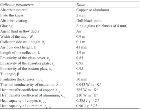
Table 1- The properties of experimental solar air heater
Çizelge 1- Deneysel hava ısıtmalı kollektörün özellikleri
Collector parameters Value
Absorber material Copper or aluminum
Plate thickness 2 mm
Absorber coating Dull black paint
Glazing Single glass (thickness of 4 mm) Agent fluid in flow ducts Air
Width of the duct, W 0.9 m Collector side wall height, he 0.1 m
Air flow duct height, D 43 mm Length of the collector, L 1.9 m Emissivity of the glass cover, εg 0.85
Emissivity of the absorber plate, εp 0.95
Emissivity of the bottom plate, εb 0.95
Tilt angle, β 35°
Insulation thicknesses, tb, te 50 mm
Thermal conductivity of insulation, λ 0.043 W m-1K-1
Heat transfer coefficient of copper, λCu 385 W m-1K-1
Heat transfer coefficient of aluminum, λAl 210 W m-1K-1
Heat capacity of copper, cp, Cu 0.385 J g-1°C-1
Heat capacity of aluminum, cp, Al 0.90 J g-1°C-1
2.2. Energy analysis and uncertainty
The energy balance for solar air heaters are given in equation 1 (Hottel & Woertz 1942; Duffie & Beckman 2006; Karwa & Chauhan 2010).
)
/(
c T uI
=
Q
A
G
η
(1) Where; Quis the useful energy gain; Acis the heater aperture area and GTis the solar radiation intensity onthe heater surface. The useful energy gain can be calculated by the equation 2.
[
L(
i a)
]
R c
u
A
F
S
U
T
T
Q
=
−
−
(2) Where; FRis the heat removal factor; S is the solar energy absorbed by heater; ULis the overall heat losscoefficient; Tiis the inlet air temperature and Tais the ambient air temperature. The heat removal factor of the
collector is defined as shown in equation 3.
{
}
(
) / (
) 1 exp
/ (
)
R p c L c L p
F
=
m c
A U
−
−
A U F m c
′
(3)Where; m is airflow rate; cpis the specific heat of air at constant pressure and F′ is the heater efficiency
factor as shown in equation 4.
(
)
[
]
{
pp c}
TG
S
α ρ α τ − −=
1 1 (4)Where;τis transmittance of transparent cover;αpis absorptance of absorber plate and ρcis reflectance of
transparent cover. The overall heat loss coefficient is the sum of top, bottom and edge heat loss coefficients as shown in equation 5. e b t L
U
U
U
U
=
+
+
(5)The top heat loss coefficient is presented in equation 6 (Duffie & Beckman 2006).
(
)
(
)
(
)
(
)
N g p f N w h N p a T pm T a T pm T w h e f N a T pm T pm TC N tU
− + − + + + + + − + − +
+
=
ε ε ε σ 133 . 0 1 2 00591 . 0 1 2 2 1 1 (6)Where; N is number of transparent cover;
C
=
520
(
1
−
0
.
000051
β
2)
; βis the heater tilt angle; Tpmis
temperature of absorbing plate,
f
=
(
1
+
0
.
089
h
w−
0
.
1166
h
wε
p)
(
1
+
0
.
07866
N
)
; εpis emissivity ofabsorbing plate,
h
w=
5 +
.
7
3
.
8
V
r; Vr is wind velocity;e
=
0
.
430
[
1
−
( )
100Tpm]
; εg is emissivity oftransparent cover. The bottom and edge heat loss coefficients are presented in equation 7 and 8, respectively:
L
U
b=
λ
/
(7)(1)
Where; Q
uis the useful energy gain; A
cis the
heater aperture area and G
Tis the solar radiation
intensity on the heater surface. The useful energy
gain can be calculated by the Equation 2.
[
L(
i a)
]
R c
u
A
F
S
U
T
T
Q
=
−
−
(2)
Where; F
Ris the heat removal factor; S is the
solar energy absorbed by heater; U
Lis the overall
heat loss coefficient; T
iis the inlet air temperature
and T
ais the ambient air temperature. The heat
removal factor of the collector is defined as shown
in Equation 3.
{
}
( ) / ( ) 1 exp / ( )
R p c L c L p
F =m c A U − −A U F m c′
(3)
Where; m is airflow rate; c
pis the specific heat
of air at constant pressure and F¢ is the heater
efficiency factor as shown in Equation 4.
( )
[
]
{
p c}
p TG
S
=
1−1τ−αα ρ(4)
Where; t is transmittance of transparent
cover; a
pis absorptance of absorber plate and r
cis
reflectance of transparent cover. The overall heat
loss coefficient is the sum of top, bottom and edge
heat loss coefficients as shown in Equation 5.
e b t
L
U
U
U
U
=
+
+
(5)
The top heat loss coefficient is presented in
Equation 6 (Duffie & Beckman 2006).
Table 1- The properties of experimental solar air heater
Çizelge 1- Deneysel hava ısıtmalı kollektörün özellikleri
Collector parameters Value
Absorber material Copper or aluminum
Plate thickness 2 mm
Absorber coating Dull black paint
Glazing Single glass (thickness of 4 mm)
Agent fluid in flow ducts Air
Width of the duct, W 0.9 m
Collector side wall height, he 0.1 m
Air flow duct height, D 43 mm
Length of the collector, L 1.9 m
Emissivity of the glass cover, εg 0.85 Emissivity of the absorber plate, εp 0.95
Emissivity of the bottom plate, εb 0.95
Tilt angle, β 35°
Insulation thicknesses, tb, te 50 mm
Thermal conductivity of insulation, l 0.043 W m-1 K-1
Heat transfer coefficient of copper, lCu 385 W m-1 K-1
Heat transfer coefficient of aluminum, lAl 210 W m-1 K-1
Heat capacity of copper, cp, Cu 0.385 J g-1 °C-1
Experimental Investigation of Various Type Absorber Plates for Solar Air Heaters, Çağlayan et al
464
Ta r ı m B i l i m l e r i D e r g i s i – J o u r n a l o f A g r i c u l t u r a l S c i e n c e s 21 (2015) 459-470Where; N is number of transparent cover;
)
000051
.
0
1
(
520
−
β
2=
C
; b is the heater
tilt angle; T
pmis temperature of absorbing plate,
)
07866
.
0
1
(
)
1166
.
0
089
.
0
1
(
h
h
N
f
=
+
w−
wε
p+
;
e
pis emissivity of absorbing plate,
h
w=
5 +
.
7
3
.
8
V
r;
V
ris wind velocity;
5
Table 1- The properties of experimental solar air heater
Çizelge 1- Deneysel hava ısıtmalı kollektörün özellikleri
Collector parameters Value
Absorber material Copper or aluminum
Plate thickness 2 mm
Absorber coating Dull black paint
Glazing Single glass (thickness of 4 mm) Agent fluid in flow ducts Air
Width of the duct, W 0.9 m Collector side wall height, he 0.1 m
Air flow duct height, D 43 mm Length of the collector, L 1.9 m Emissivity of the glass cover, εg 0.85
Emissivity of the absorber plate, εp 0.95
Emissivity of the bottom plate, εb 0.95
Tilt angle, β 35°
Insulation thicknesses, tb, te 50 mm
Thermal conductivity of insulation, λ 0.043 W m-1K-1
Heat transfer coefficient of copper, λCu 385 W m-1K-1
Heat transfer coefficient of aluminum, λAl 210 W m-1K-1
Heat capacity of copper, cp, Cu 0.385 J g-1°C-1
Heat capacity of aluminum, cp, Al 0.90 J g-1°C-1
2.2. Energy analysis and uncertainty
The energy balance for solar air heaters are given in equation 1 (Hottel & Woertz 1942; Duffie & Beckman 2006; Karwa & Chauhan 2010).
)
/(
c T uI
=
Q
A
G
η
(1) Where; Quis the useful energy gain; Acis the heater aperture area and GTis the solar radiation intensity onthe heater surface. The useful energy gain can be calculated by the equation 2.
[
L(
i a)
]
R c
u
A
F
S
U
T
T
Q
=
−
−
(2) Where; FRis the heat removal factor; S is the solar energy absorbed by heater; ULis the overall heat losscoefficient; Tiis the inlet air temperature and Tais the ambient air temperature. The heat removal factor of the
collector is defined as shown in equation 3.
{
}
(
) / (
) 1 exp
/ (
)
R p c L c L p
F
=
m c
A U
−
−
A U F m c
′
(3)Where; m is airflow rate; cpis the specific heat of air at constant pressure and F′ is the heater efficiency
factor as shown in equation 4.
(
)
[
]
{
p c}
p TG
S
α ρ α τ − −=
1 1 (4)Where;τis transmittance of transparent cover;αpis absorptance of absorber plate and ρcis reflectance of
transparent cover. The overall heat loss coefficient is the sum of top, bottom and edge heat loss coefficients as shown in equation 5. e b t L
U
U
U
U
=
+
+
(5)The top heat loss coefficient is presented in equation 6 (Duffie & Beckman 2006).
(
)
(
)
(
)
(
)
N g p f N w h N p a T pm T a T pm T w h e f N a T pm T pm TC N tU
− + − + + + + + − + − +
+
=
ε ε ε σ 133 . 0 1 2 00591 . 0 1 2 2 1 1 (6)Where; N is number of transparent cover;
C
=
520
(
1
−
0
.
000051
β
2)
; βis the heater tilt angle; Tpmis
temperature of absorbing plate,
f
=
(
1
+
0
.
089
h
w−
0
.
1166
h
wε
p)
(
1
+
0
.
07866
N
)
; εp is emissivity ofabsorbing plate,
h
w=
5 +
.
7
3
.
8
V
r; Vr is wind velocity;e
=
0
.
430
[
1
−
( )
100Tpm]
; εg is emissivity oftransparent cover. The bottom and edge heat loss coefficients are presented in equation 7 and 8, respectively:
L
U
b=
λ
/
(7); e
gis
emissivity of transparent cover. The bottom and
edge heat loss coefficients are presented in Equation
7 and 8, respectively:
L
U
b=
λ
/
(7)
)
/
1
(
)
/
(
c ec
h
L
A
U
=
λ
(8)
Where; l is thermal conductivity of insulation
material; L is the thickness of insulation material;
c is the perimeter of heater; h is the heater height.
The collector efficiency factor F¢ is calculated by
the Equation 9 and 10.
6
)
/
1
(
)
/
(
c ec
h
L
A
U
=
λ
(8) Where; λ is thermal conductivity of insulation material; L is the thickness of insulation material; c is the perimeter of heater; h is the heater height. The collector efficiency factor F′ is calculated by the equation 9 and 10.)
/(
U
LF
′
=
α
α
+
(9) hD
Nu /
λ
α
=
(10)Errors and uncertainties in the experiments can arise from instrument selection, condition, calibration, environment, observation, reading and test planning. In these experiments, mass flow rate, ambient, inlet and outlet air temperatures, wind speed and solar radiation were measured with appropriate instruments. The result R is a given function in terms of the independent variables. Let wRbe the uncertainty in the result
and w1, w2, … , wnbe the uncertainties in the independent variables. If the uncertainties in the independent
variables are all given with same odds, then uncertainty in the result having these odds is given in equation 11 (Akpınar 2006). 2 / 1 2 2 2 2 2 1 1 ... ∂ ∂ + + ∂ ∂ + ∂ ∂ = n n R xRw xR w xR w w (11)
For example, the total uncertainty in the measurement of the ambient air temperature (wTa) may be calculated as
from the equation 12 and 13 (Ayadi et al 2014).
( )
( )
( )
[
2 2 2]
1/2 tm cp th Ta w w w w = + + (12)(
) (
) (
)
[
2 2 2]
1/2 25 . 0 05 . 0 25 . 0 + + = Ta w =0.36 (13)Where; wth,, arisen from thermocouple; wcp, arisen from connection points; wtm, arisen from temperature
measurement.
During the experiments, total uncertainties of the measured parameters were presented in Table 2.
Table 2- Uncertainties of the parameters during experiments
Çizelge 2- Denemelerdeki parametrelerin belirsizlikleri
Parameter (unit) Comment
Uncertainty in the measurement of temperature
- Ambient air temperature (°C) ±0.368
- Inlet air temperature (°C) ±0.652
- Outlet air temperature (°C) ±0.368
Uncertainty in the measurement of mass flow rate (m s-1) ±0.165
Uncertainty in the measurement of wind speed (m s-1) ±0.152
Uncertainty in the measurement of solar radiation (W s-2) ±0.531
Total uncertainty for collector thermal efficiency can be written as in equation 14 and 15.
1/2 2 2 2 2 2 2 a in out r T m T T T V G a in out r T w w w w w w w m T T T V G η
η
η
η
η
η
η
∂ ∂ ∂ ∂ ∂ ∂ = + + + + + ∂ ∂ ∂ ∂ ∂ ∂
(14)(
) (
) (
) (
) (
) (
)
[
0.1652 + 0.3682 + 0.652 2+ 0.368 2 + 0.1522 + 0.5312]
1/2 =1.014 = η w (15)3. Results and Discussions
Experiments were performed between 19thJuly and 1st September 2012 at the Akdeniz University, Antalya,
Turkey (36° N latitude; 30° E longitude). All the heaters were placed facing south and with a tilt angle of 35°. The experiments were carried out at the same time periods between 08:30 and 17:00 of the days for a fixed air flow rate and the data collected each 5 min during the experiments, but the results were discussed and evaluated where the solar radiation are more than 630 W m-2(Ion & Martins 2006).
The energy efficiencies of Al and Cu absorber types (Type I, II, III and IV) were compared with each other for airflow velocity of 2 m s-1(Figure 3-6).
(9)
6)
/
1
(
)
/
(
c ec
h
L
A
U
=
λ
(8) Where; λ is thermal conductivity of insulation material; L is the thickness of insulation material; c is the perimeter of heater; h is the heater height. The collector efficiency factor F′ is calculated by the equation 9 and 10.)
/(
U
LF
′
=
α
α
+
(9) hD
Nu /
λ
α
=
(10)Errors and uncertainties in the experiments can arise from instrument selection, condition, calibration, environment, observation, reading and test planning. In these experiments, mass flow rate, ambient, inlet and outlet air temperatures, wind speed and solar radiation were measured with appropriate instruments. The result R is a given function in terms of the independent variables. Let wRbe the uncertainty in the result
and w1, w2, … , wnbe the uncertainties in the independent variables. If the uncertainties in the independent
variables are all given with same odds, then uncertainty in the result having these odds is given in equation 11 (Akpınar 2006). 2 / 1 2 2 2 2 2 1 1 ... ∂ ∂ + + ∂ ∂ + ∂ ∂ = n n R xRw xR w xR w w (11)
For example, the total uncertainty in the measurement of the ambient air temperature (wTa) may be calculated as
from the equation 12 and 13 (Ayadi et al 2014).
( )
( )
( )
[
2 2 2]
1/2 tm cp th Ta w w w w = + + (12)(
) (
) (
)
[
2 2 2]
1/2 25 . 0 05 . 0 25 . 0 + + = Ta w =0.36 (13)Where; wth,, arisen from thermocouple; wcp, arisen from connection points; wtm, arisen from temperature
measurement.
During the experiments, total uncertainties of the measured parameters were presented in Table 2.
Table 2- Uncertainties of the parameters during experiments
Çizelge 2- Denemelerdeki parametrelerin belirsizlikleri
Parameter (unit) Comment
Uncertainty in the measurement of temperature
- Ambient air temperature (°C) ±0.368
- Inlet air temperature (°C) ±0.652
- Outlet air temperature (°C) ±0.368
Uncertainty in the measurement of mass flow rate (m s-1) ±0.165
Uncertainty in the measurement of wind speed (m s-1) ±0.152
Uncertainty in the measurement of solar radiation (W s-2) ±0.531
Total uncertainty for collector thermal efficiency can be written as in equation 14 and 15.
1/2 2 2 2 2 2 2 a in out r T m T T T V G a in out r T w w w w w w w m T T T V G η
η
η
η
η
η
η
∂ ∂ ∂ ∂ ∂ ∂ = + + + + + ∂ ∂ ∂ ∂ ∂ ∂
(14)(
) (
) (
) (
) (
) (
)
[
0.1652 + 0.3682 + 0.652 2+ 0.368 2 + 0.1522 + 0.5312]
1/2 =1.014 = η w (15)3. Results and Discussions
Experiments were performed between 19thJuly and 1st September 2012 at the Akdeniz University, Antalya,
Turkey (36° N latitude; 30° E longitude). All the heaters were placed facing south and with a tilt angle of 35°. The experiments were carried out at the same time periods between 08:30 and 17:00 of the days for a fixed air flow rate and the data collected each 5 min during the experiments, but the results were discussed and evaluated where the solar radiation are more than 630 W m-2(Ion & Martins 2006).
The energy efficiencies of Al and Cu absorber types (Type I, II, III and IV) were compared with each other for airflow velocity of 2 m s-1(Figure 3-6).
(10)
Errors and uncertainties in the experiments
can arise from instrument selection, condition,
calibration, environment, observation, reading and
test planning. In these experiments, mass flow rate,
ambient, inlet and outlet air temperatures, wind
speed and solar radiation were measured with
appropriate instruments. The result R is a given
function in terms of the independent variables. Let
w
Rbe the uncertainty in the result and w
1, w
2,… , w
nbe the uncertainties in the independent variables. If
the uncertainties in the independent variables are all
given with same odds, then uncertainty in the result
having these odds is given in Equation 11 (Akpınar
2006).
2 / 1 2 2 2 2 2 1 1 ... ∂ ∂ + + ∂ ∂ + ∂ ∂ = n n R xRw xR w xRw w(11)
For example, the total uncertainty in the
measurement of the ambient air temperature (w
Ta)
may be calculated as from the Equation 12 and 13
(Ayadi et al 2014).
6)
/
1
(
)
/
(
c ec
h
L
A
U
=
λ
(8) Where; λ is thermal conductivity of insulation material; L is the thickness of insulation material; c is the perimeter of heater; h is the heater height. The collector efficiency factor F′ is calculated by the equation 9 and 10.)
/(
U
LF
′
=
α
α
+
(9) hD
Nu /
λ
α
=
(10)Errors and uncertainties in the experiments can arise from instrument selection, condition, calibration, environment, observation, reading and test planning. In these experiments, mass flow rate, ambient, inlet and outlet air temperatures, wind speed and solar radiation were measured with appropriate instruments. The result R is a given function in terms of the independent variables. Let wRbe the uncertainty in the result
and w1, w2,… , wnbe the uncertainties in the independent variables. If the uncertainties in the independent
variables are all given with same odds, then uncertainty in the result having these odds is given in equation 11 (Akpınar 2006). 2 / 1 2 2 2 2 2 1 1 ... ∂ ∂ + + ∂ ∂ + ∂ ∂ = n n R xR w xRw xR w w (11)
For example, the total uncertainty in the measurement of the ambient air temperature (wTa) may be calculated as
from the equation 12 and 13 (Ayadi et al 2014).
( )
( )
( )
[
2 2 2]
1/2 tm cp th Ta w w w w = + + (12)(
) (
) (
)
[
2 2 2]
1/2 25 . 0 05 . 0 25 . 0 + + = Ta w =0.36 (13)Where; wth,, arisen from thermocouple; wcp, arisen from connection points; wtm, arisen from temperature
measurement.
During the experiments, total uncertainties of the measured parameters were presented in Table 2.
Table 2- Uncertainties of the parameters during experiments
Çizelge 2- Denemelerdeki parametrelerin belirsizlikleri
Parameter (unit) Comment
Uncertainty in the measurement of temperature
- Ambient air temperature (°C) ±0.368
- Inlet air temperature (°C) ±0.652
- Outlet air temperature (°C) ±0.368
Uncertainty in the measurement of mass flow rate (m s-1) ±0.165
Uncertainty in the measurement of wind speed (m s-1) ±0.152
Uncertainty in the measurement of solar radiation (W s-2) ±0.531
Total uncertainty for collector thermal efficiency can be written as in equation 14 and 15.
1/2 2 2 2 2 2 2 a in out r T m T T T V G a in out r T w w w w w w w m T T T V G η
η
η
η
η
η
η
∂ ∂ ∂ ∂ ∂ ∂ = + + + + + ∂ ∂ ∂ ∂ ∂ ∂
(14)(
) (
) (
) (
) (
) (
)
[
0.165 2+ 0.368 2+ 0.6522 + 0.3682 + 0.152 2+ 0.5312]
1/2 =1.014 = η w (15)3. Results and Discussions
Experiments were performed between 19thJuly and 1stSeptember 2012 at the Akdeniz University, Antalya,
Turkey (36° N latitude; 30° E longitude). All the heaters were placed facing south and with a tilt angle of 35°. The experiments were carried out at the same time periods between 08:30 and 17:00 of the days for a fixed air flow rate and the data collected each 5 min during the experiments, but the results were discussed and evaluated where the solar radiation are more than 630 W m-2(Ion & Martins 2006).
The energy efficiencies of Al and Cu absorber types (Type I, II, III and IV) were compared with each other for airflow velocity of 2 m s-1(Figure 3-6).
(12)
6)
/
1
(
)
/
(
c ec
h
L
A
U
=
λ
(8) Where; λ is thermal conductivity of insulation material; L is the thickness of insulation material; c is the perimeter of heater; h is the heater height. The collector efficiency factor F′ is calculated by the equation 9 and 10.)
/(
U
LF
′
=
α
α
+
(9) hD
Nu /
λ
α
=
(10)Errors and uncertainties in the experiments can arise from instrument selection, condition, calibration, environment, observation, reading and test planning. In these experiments, mass flow rate, ambient, inlet and outlet air temperatures, wind speed and solar radiation were measured with appropriate instruments. The result R is a given function in terms of the independent variables. Let wRbe the uncertainty in the result
and w1, w2,… , wnbe the uncertainties in the independent variables. If the uncertainties in the independent
variables are all given with same odds, then uncertainty in the result having these odds is given in equation 11 (Akpınar 2006). 2 / 1 2 2 2 2 2 1 1 ... ∂ ∂ + + ∂ ∂ + ∂ ∂ = n n R xR w xRw xR w w (11)
For example, the total uncertainty in the measurement of the ambient air temperature (wTa) may be calculated as
from the equation 12 and 13 (Ayadi et al 2014).
( )
( )
( )
[
2 2 2]
1/2 tm cp th Ta w w w w = + + (12)(
) (
) (
)
[
2 2 2]
1/2 25 . 0 05 . 0 25 . 0 + + = Ta w =0.36 (13)Where; wth,, arisen from thermocouple; wcp, arisen from connection points; wtm, arisen from temperature
measurement.
During the experiments, total uncertainties of the measured parameters were presented in Table 2.
Table 2- Uncertainties of the parameters during experiments
Çizelge 2- Denemelerdeki parametrelerin belirsizlikleri
Parameter (unit) Comment
Uncertainty in the measurement of temperature
- Ambient air temperature (°C) ±0.368
- Inlet air temperature (°C) ±0.652
- Outlet air temperature (°C) ±0.368
Uncertainty in the measurement of mass flow rate (m s-1) ±0.165
Uncertainty in the measurement of wind speed (m s-1) ±0.152
Uncertainty in the measurement of solar radiation (W s-2) ±0.531
Total uncertainty for collector thermal efficiency can be written as in equation 14 and 15.
1/2 2 2 2 2 2 2 a in out r T m T T T V G a in out r T w w w w w w w m T T T V G η
η
η
η
η
η
η
∂ ∂ ∂ ∂ ∂ ∂ = + + + + + ∂ ∂ ∂ ∂ ∂ ∂
(14)(
) (
) (
) (
) (
) (
)
[
0.165 2+ 0.368 2+ 0.6522 + 0.3682 + 0.152 2+ 0.5312]
1/2 =1.014 = η w (15)3. Results and Discussions
Experiments were performed between 19thJuly and 1stSeptember 2012 at the Akdeniz University, Antalya,
Turkey (36° N latitude; 30° E longitude). All the heaters were placed facing south and with a tilt angle of 35°. The experiments were carried out at the same time periods between 08:30 and 17:00 of the days for a fixed air flow rate and the data collected each 5 min during the experiments, but the results were discussed and evaluated where the solar radiation are more than 630 W m-2(Ion & Martins 2006).
The energy efficiencies of Al and Cu absorber types (Type I, II, III and IV) were compared with each other for airflow velocity of 2 m s-1(Figure 3-6).
(13)
Where; w
th,, arisen from thermocouple; w
cp,
arisen from connection points; w
tm,
arisen from
temperature measurement.
During the experiments, total uncertainties of
the measured parameters were presented in Table 2.
5
Table 1- The properties of experimental solar air heater
Çizelge 1- Deneysel hava ısıtmalı kollektörün özellikleri
Collector parameters Value
Absorber material Copper or aluminum
Plate thickness 2 mm
Absorber coating Dull black paint
Glazing Single glass (thickness of 4 mm) Agent fluid in flow ducts Air
Width of the duct, W 0.9 m Collector side wall height, he 0.1 m
Air flow duct height, D 43 mm Length of the collector, L 1.9 m Emissivity of the glass cover, εg 0.85
Emissivity of the absorber plate, εp 0.95
Emissivity of the bottom plate, εb 0.95
Tilt angle, β 35°
Insulation thicknesses, tb, te 50 mm
Thermal conductivity of insulation, λ 0.043 W m-1K-1
Heat transfer coefficient of copper, λCu 385 W m-1K-1
Heat transfer coefficient of aluminum, λAl 210 W m-1K-1
Heat capacity of copper, cp, Cu 0.385 J g-1°C-1
Heat capacity of aluminum, cp, Al 0.90 J g-1°C-1
2.2. Energy analysis and uncertainty
The energy balance for solar air heaters are given in equation 1 (Hottel & Woertz 1942; Duffie & Beckman 2006; Karwa & Chauhan 2010).
)
/(
c T uI
=
Q
A
G
η
(1) Where; Quis the useful energy gain; Acis the heater aperture area and GTis the solar radiation intensity onthe heater surface. The useful energy gain can be calculated by the equation 2.
[
L(
i a)
]
R c
u
A
F
S
U
T
T
Q
=
−
−
(2) Where; FRis the heat removal factor; S is the solar energy absorbed by heater; ULis the overall heat losscoefficient; Tiis the inlet air temperature and Tais the ambient air temperature. The heat removal factor of the
collector is defined as shown in equation 3.
{
}
(
) / (
) 1 exp
/ (
)
R p c L c L p
F
=
m c
A U
−
−
A U F m c
′
(3)Where; m is airflow rate; cpis the specific heat of air at constant pressure and F′ is the heater efficiency
factor as shown in equation 4.
(
)
[
]
{
pp c}
TG
S
α ρ α τ − −=
1 1 (4)Where;τis transmittance of transparent cover;αpis absorptance of absorber plate and ρcis reflectance of
transparent cover. The overall heat loss coefficient is the sum of top, bottom and edge heat loss coefficients as shown in equation 5. e b t L
U
U
U
U
=
+
+
(5)The top heat loss coefficient is presented in equation 6 (Duffie & Beckman 2006).
(
)
(
)
(
)
(
)
N g p f N w h N p a T pm T a T pm T w h e f N a T pm T pm TC N tU
− + − + + + + + − + − +
+
=
ε ε ε σ 133 . 0 1 2 00591 . 0 1 2 2 1 1 (6)Where; N is number of transparent cover;
C
=
520
(
1
−
0
.
000051
β
2)
; βis the heater tilt angle; Tpmis
temperature of absorbing plate,
f
=
(
1
+
0
.
089
h
w−
0
.
1166
h
wε
p)
(
1
+
0
.
07866
N
)
; εpis emissivity ofabsorbing plate,
h
w=
5 +
.
7
3
.
8
V
r; Vr is wind velocity;e
=
0
.
430
[
1
−
( )
100Tpm]
; εg is emissivity oftransparent cover. The bottom and edge heat loss coefficients are presented in equation 7 and 8, respectively:
L
U
b=
λ
/
(7)(6)
Table 2- Uncertainties of the parameters during experiments
Çizelge 2- Denemelerdeki parametrelerin belirsizlikleri
Parameter (unit) Comment
Uncertainty in the measurement of temperature
- Ambient air temperature (°C) ±0.368
- Inlet air temperature (°C) ±0.652
- Outlet air temperature (°C) ±0.368
Uncertainty in the measurement of mass flow rate (m s-1) ±0.165
Uncertainty in the measurement of wind speed (m s-1) ±0.152