Doğuş-USV Unmanned Sea Vehicle
Obstacle Localization with Stereo Vision and Path Planning
Ebru Dağlı, Dilek Tükel
Control&Automation Engineering Doğuş University Istanbul, Turkey [email protected]Caner Civan
Computer Engineering Doğuş University Istanbul, TurkeyAbstract—Unmanned vehicle systems are becoming increasingly prevalent on the land, in the sea, and in the air. Navigation and path planning in an unknown environment are important tasks for future generation. The objective of this work is to design an unmanned sea vehicle and necessary software that can perform path planning autonomously with using stereo vision. In this paper using potential field algorithm, collision free path is achieved from a starting point to a terminal point.
Keywords—stereo vision; path planning; unmanned sea vehicle;
I. INTRODUCTION
Sea power is a very important factor in military, commercial and transportation applications. There is a great interest in unmanned vehicles in the maritime do-main from military and research institutes. The history of unmanned vehicles has its roots as far back as 425 BC [1]. The first self-flying robot bird is propelled by compressed air. Modern concepts were begun to be developed during the First and Second World Wars. The first navy USV’s were radio-controlled drone boats which was used for collecting radioactive water samples (1946) and performing mine clearance operations (1960s). In 1985, the first modern USV “The Owl” was designed around the base of a jet-ski by International Robotic Systems Inc. In 1995, Navtec Inc was established and developed a fully autonomous navigation system using global positioning system and compasses along with a radar-based obstacle avoidance system. The MK II [2] was the first USV to be deployed for a real world mission in 1995 in the Middle East. There are also many academic re-search projects involved in the development of USVs. Several Catamaran type USVs have been developed such as SESAMO, an Italian catamaran USV [1]. In 2004, the Marine and Industrial Dynamic Analysis (MIDAS) Research Group at Plymouth University designed a twin-hull catamaran USV named Springer [3]. Springer research programme aimed to design and build a new advanced intelligent integrated navigation and autopilot (IINA) system.
Energy efficiency and use of renewable energy are very important for long missions. Wave powered USV “Wave
Glider” has this ability and it crossed the Pacific Ocean, the longest distance ever attempted by a USV in 2012 [11].
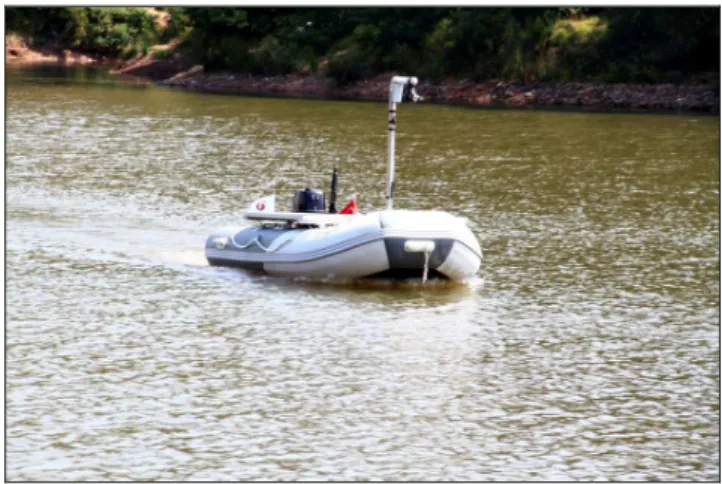
The Dogus Unmanned Sea Vehicle (Dogus-USV) project[4] is funded by Dogus University with the goal of reconnaissance and surveillance of the Turkish coasts. Being unmanned makes it possible for the vehicle to stay in the open sea for a long time without returning to base. It uses solar energy and maneuvers into different positions and paths using onboard cameras and global positioning system (GPS). As shown in Fig. 1, it is equipped with solar panels and batteries. The specifications of the vehicle are given in table 1.
Fig. 1.USV trials on Aydos lake, 05, July, 2012 TABLE I. THE SPECIFICATIONS OF DOGUS-USV
Weight 256 kg
Length/Width/Height 330/151/110 (cm)
Power 5 HP
Speed 16 knot
Motor Parsun F5ERL
Motor Cooling Water
Batteries Gel
Battery Capacity 100 Ah per battery
Number of Batteries 4
Solar Panels Lorentz LA-Series
Solar Panel efficiency For 10 year 90%, for 20 year 80%
Controller U1 Ultra PC-Intel Atom Z520 single core, 1.33 GHz
Communication WiFi, GPS, RF, 3G
Vehicle Controller Arduino Mega 2560
II. SYSTEM COMPONENTS
The Dogus-USV was constructed as a sea vehicle that could be either remotely controlled or autonomous. The team designed and built the boat starting with the body of an inflatable boat and modified it to fit an electric motor, propellers, U1 computer, microcontroller, sensors, cameras, batteries, and solar panels. The components are selected and constructed to perform long missions in harsh environments without stopping or recharging. Dogus-USV is designed to be able to operate in harsh sea conditions; it is equipped with sensors that can instantly report errors to the control center. The movement of the rudder is achieved via mechanical steering with a geared motor and a powered chain.
A. Motor Specifications
The vehicle is powered by a high efficiency brushless motor. Max power is 4.8 KW (over 6hp) but this motor is rated at 5 hp continuous. It has a high current protection system. The water-cooled version is preferred since the boat is de-signed to work over long ranges. It needs 100 amps of continuous current and a 10 second “power boost” of 140 amps for full speed. It needs a 48 V DC battery system. The inverter box is also water cooled. For the forward and reverse modes, relay based on-off control is applied. A servo motor is used for changing speed. There is also another relay that cuts the power using a different channel in case of an emergency. Standard props are used. We have installed and tested our system in a lake with great results.
B. Solar Panels
The boat can supply its own energy and completely refill its empty batteries in 7 hours from its solar panels (Fig. 1). The power supply consists of two solar panels of 130 W, four marine gel batteries of 100 Ah for 12 V each. The panels are highly efficient and durable against sea water. The panel surface is coated with a hydrophobic layer. The dimension of each solar panel is 669x1556x37mm and its weight is 16 kg. C. Batteries
The marine gel type batteries selected can power the electric motor for up to 6 hours at top speed. Lead acid gel batteries are common choice for sea vehicles to prevent foaming. Four accumulators have been placed in Dogus-USV with care being taken to ensure they balance correctly.
D. Rudder
The rudder is driven using a 214:1 gear head motor. An external encode shown in Fig. 4 is mounted to measure the position of the rudder
E. Solar Panel Charge Controller Circuit
This is a waterproof circuit controlling the current flowing from the solar panels to the batteries.
Fig. 2 Rudder mechanism an external encoder- ϕ 50mm-500 pulses/turn.
F. Inverter
An inverter is a critical component, performing voltage and DC/AC conversion to recharge the batteries which it can do in under 5 hours.
G. Vision
Two Internet Protocol Cameras (IP Cam) are installed in the USV. Each camera is built upon a 640 x 480 pixels resolution image sensor with digital output. The camera (Fig. 3) allows about 330 degrees of horizontal pan and about 70 degrees of tilt and has night vision capability supported by ten infrared illuminators built in.
III. STEREO VISION
A simple model of an organic vision system includes two sensors, the eyes, connected to the brain by a tightly packed bundle of nerves [5]. Stereo vision is a common for obtaining the three dimensional position of objects from two or more simultaneous views of a scene. In stereo vision system the depth of information is not measured directly it is extrapolated from the binocular images by helps of disparity.
Fig. 3:Stereo Camera system
A. Camera Geometry
The pinhole camera model defines the geometric relationship between a 3D point and its 2D corresponding projection onto the image plane. When using a pinhole camera
model, this geometric mapping of three dimensions onto two, is called a perspective projection [6].
Pinhole camera consists of two planes: the image plane and the focal plane with the optical center C (also known as camera projection centre as shown in Fig. 4.) The image is formed in the image plane and the focal plane is parallel to the image plane on a distance which called focal length (f).
According to pinhole camera model, a three dimentional point P
(
X,Y,Z)
in space is formated two dimentional point of which an intersection of straight line from P to the center of the image plane. The knowledge of similar triangles point of f Z Y f Z X f
P , , can be mapped from point of P
(
X,Y,Z)
.Fig. 4. Camera geometry
Given that distance from the center of the image plane of the projection f, the actual size of the object on the image plane size : Z X f X'=− , Z Y f Y'=− (1)
Fig. 5. Camera Coordinates System
The system for modeling two cameras consists of three different coordinate systems, the world reference frame
( ) ( ) ( )
(
X W ,YW ,ZW)
the camera frame(
( ) ( ) ( )C C C)
Z YX , , with
the optical centre as origin and the image frame
( )
U ,V . (figure 5)Camera model could be displayed with using homogeneous coordinates as a linear equation:
AX
X
'
=
(2)The relationship between a 3D point M and its image m projection is given linearly by the formula;
m=A[RT]M (3)
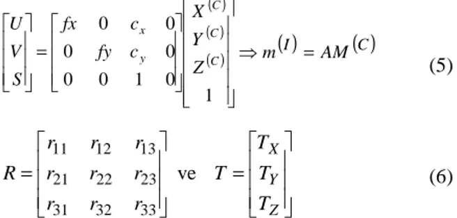
where A is the camera intrinsic matrix:
(4)
(cx, cy) are coordinates of the principal point; (fx, fy) are the focal lengths by the axes x and y;
(5) = = Z Y X T T T T r r r r r r r r r R ve 33 32 31 23 22 21 13 12 11 (6)
(R,T) are extrinsic parameters: the rotation matrix R and translation vector T that relate the world coordinate system to the camera coordinate system.
(7)
In summary, a point given in world coordinates is transformed onto a two dimensional image plane using the following equation () :
(8)
(9)
Pinhole camera model is characterized by two types of parameter set. There are four intrinsic camera parameters; two are for the position of the origin of the image coordinate frame, and two are for the scale factors of the axes of this frame. There are six extrinsic camera parameters: three are for the position of the center of projection, and three are for the orientation of the image plane coordinate frame [7].
To compute a comparison between two images captured from two different cameras, intrinsic and extrinsic parameters are essential.
1
0
0
0
0
=
y y x xc
f
c
f
A
( ) ( ) ( ) = 1 0 1 0 0 0 0 0 0 C C C y x Z Y X c fy c fx S V U( )
I AM( )
C m = ⇒ ( ) ( ) ( ) ( ) ( ) ( )W ( )C ( )W W W C C CDM
M
Z
Y
X
T
R
Z
Y
X
=
⇒
=
× × ×1
1
0
1
3 1 1 3 3 3 ( )I ( )C ( )C ( )W ( )I ( )WPDM
m
DM
M
PM
m
=
,
=
⇒
=
( ) ( ) ( ) = × × × 1 1 0 0 1 0 0 0 0 0 0 3 1 1 3 3 3 W W W y y x x Z Y X T R c f c f S V UB. Two view Geometry
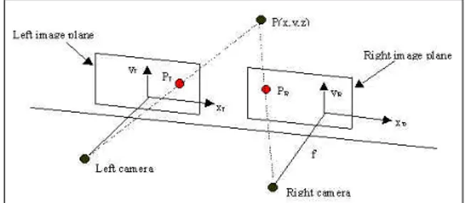
The image planes of the two cameras are arranged as coplanar and collinear with identical optical characteristics to acquire the stereo image pair. This can be illustrated as fig. 6.
Fig. 6. Parallel axes geometry
P(x, y, z) – a general scene point, which is projected to PL on the left image and PR on the right image; (xL, yL), (xR,yR)
and (x, y, z) represent left coordinates, right coordinates and global coordinates respectively.
Because of the cameras are fastened horizontally, the vertical component of the disparity vectors is always zero.
Fig. 7. Diagram for depth calculation and disparity
The depth of an object, z-f, is inversely proportional to the disparity, which is given by:
d B f f
Z− = * (10)
Equation (10) is obtained from Figure 7.
C. Simplification of Stereo Vision Range Calculation The dynamic movements of cameras which displaced horizontally from one to another, are eliminated in order to simplify control variables. Because of the usage of same featured cameras, both of them have the same camera parameters such as field of view. The range (R) to an object in the image plane is calculated using a scaled ratio of the total number of horizontal pixels (C) divided by the horizontal shift between the left image (xL) and right image (xR).
) ( 3 R R W f R R X X D L − R + = (11)
In order to find the distance of objects Equation(11) is arranged as: ) ( 1 X X C R L const R − = and,
W
fT
D Cconst 3=
(12)The values for distance between camera sensors (D3), focal length (F), total number of pixels across width of sensor (T), and width of sensor (W) that make up the constant (C) .
The constant C could be calculated experimentally [5].
IV. PATH PLANNING
The purpose of path planning is finding a short and complete path from the starting location of the robot to the target location without any collision avoiding obstacles. The basic concept of the potential field method is to fill the robot’s workspace with an artificial potential field in which the robot is attracted to its goal position and is repulsed away from the obstacles [8].
In general, the USV is represented as a particle under the influence of an scalar potential field U , defined as:
repulsive attractive
U
U
U
=
+
(13)
The vector field of artificial forces F(q) is given by the gradient of U : rep att U U q F( )=−∇ +∇ (14)
The most commonly used form of potential field functions proposed by Kathib [9] is defined as:
) , ( 2 1 ) ( m goal att q d qq U = ξ (15)
In the equations q is the current coordinates of the vehicle,
ζ is the scaling factor and d(q,qhedef) is the distance between the robot q and the goal qgoal, and m = 1 or 2. For m = 1, the attractive potential is conic in shape and the resulting attractive force has constant amplitude except at the goal, where Uatt is singular. For m= 2, the attractive potential is parabolic in shape. The corresponding attractive force is then given by the negative gradient of the attractive potential.
) ( ) ( ) (q U q q q e
Fattractiv =−∇ repulsive =
ξ
goal− (16)Because the responsibility of generated collision avoidance is belonging to repulsive field, sources of repulsive fields are obstacles.
> ≤ − = 0 0 0 ) , ( 0 ) , ( ) 1 ) , ( 1 ( 2 1 ) ( d q q d if d q q d if d q q d q Urep obst obst obst
η
(17)Where η is a positive scaling factor,
d
(
q
,
q
obst)
denotes the minimal distance from the robot q to the obstacle,q
obst denotes the point on the obstacle such that the distance between this point and the robot is minimal between the obstacle and the robot, andd
0 is a positive constant denoting the distance of influence of the obstacle. > ≤ ∇ = 0 0 2 ) , ( 0 ) , ( ) , ( ) , ( 1 ) ( d q q d if d q q d if q q d q q d q Fatt obst obst obst obst (18) Combination of repulsive and attractive potential fields helps to find a path which generate robot to reach to the required location by avoiding any collision to obstacles.
In many cases, the potential field method can calculate the route to the destination successfully. In some cases, falling into local minima may fail to reach a destination. For this case, we need to improve our algorithm.
V. EXPERIMENTAL RESULTS
A. Camera Calibration
One of the basic tasks in stereo vision is to calibrate the cameras together in order to obtain the parameters that will allow you to calculate the distance of an object or 3D information of the scene. These internal and external parameters could be found by Bouguet’s camera calibration toolbox[10].
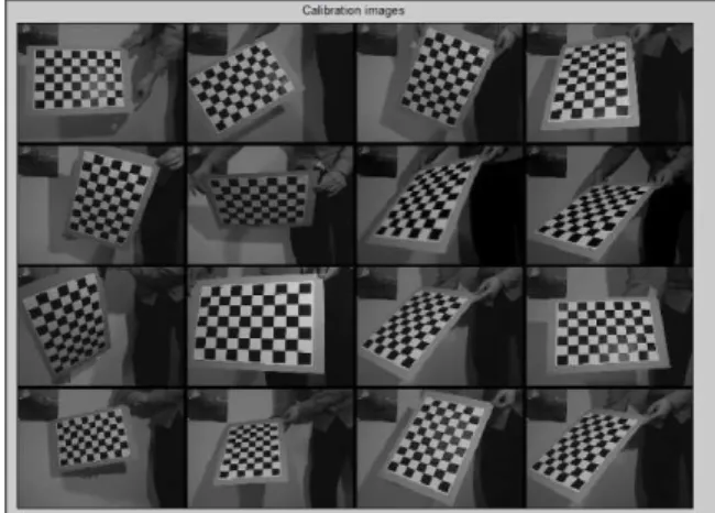
In stereo camera calibration firstly each camera calibrated separately with grabbing and saving multiple views of an calibration object like a chessboard in various positions and orientations with stereo camera using Matlab. The more variety of positions and orientations of the chessboard in the images, the better calibration results of stereo camera system. After that, the internal and external parameters were calculated by the algorithm.
B. Obstacle Recognition
Images imported in computer are defined by only numbers. There is more than one way to encode a picture by using different color spaces. The most common type is RGB space, each color is described as a combination of three main colors,
namely Red, Green and Blue. However, brightness of the environment, the signal to be pale and technical reasons arising from camera, RGB color space is not suitable to determine an area. Concerning vision system success an algorithm was needed which could effectively separate red, green, yellow, and blue obstacles from the rest of the scene. In contrast to RGB color space was not robust enough to allow the detection of yellow easily from the scene, so the HSV (hue, saturation and value) color space is used. It is found that the different color obstacles could be easily separated using just the Hue and Saturation components of the HSV color space as shown in the figure (9).
Fig. 8. Calibration Images from Different Distances and Orientations
Fig. 9. Hue – Saturation – Value aspect of the original image
Fig. 10. Histograms of a)Hue Value b)Saturation value c)value value d)all bands values
First of all to be converted HSV space, subsequently binary image form and the noise values with various filtering methods have been destroyed, so that only the yellow, red and blue balls are masked.
Left Image Right Image
Fig 11. Coordinates of obstacles
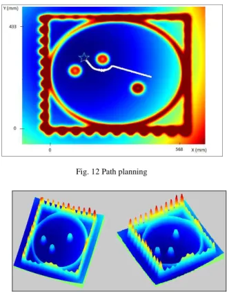
After center of gravity coordinates and radius information of obstacles are obtained and scaled by algorithm, all of them mapped according to bird’s eye view. The bird's-eye view of three ball is shown in figure 12. It can be noticed that the goal is located at the minimum point here which is shown with dark blue areas. Red areas represent higher grounds in the sphere world. Figure 13 is the 3D view of the potential field shown in figure 12.
Fig. 12 Path planning
Fig. 13. 3D view of the potential field
Vision and navigation algorithms we have coded are tested in the laboratory environment. In figure 14, the user interface of our software is shown. The next step of this work is to
implement and improve our algorithms for the real environment in real time.
Fig. 14 Doğuş-USV path planning interface
CONCLUSION
Computer vision and artificial path planning in an unknown cluttered environment are important tasks for autonomous future generation. We have built an unmanned sea vehicle with the goal of reconnaissance and surveillance. At the first step, we tested our hardware and basic software components. At the second step, the stereo vision system is integrated to the Doğuş-USV for self-localization and object recognition. Using potential field algorithm, the obstacle’s location is mapped and a collision free path is driven from the starting point to the destination point is obtained.
REFERENCES
[1] A. Motwani, “A Survey of Uninhabited Surface Vehicles”,MIDAS Technical Report: MIDAS.SMSE. 2012.TR.001 , 2012
[2] OwlMKII, https://www.wamiltons.com/project/index.php
[3] Springer: The Unmanned Surface Vehicle, Plymouth University, UK.
www.springer-usv.com
[4] S. Batı, H.A. Oğul, C. Karaçizmeli, D.B. Tükel, “Human-Computer Interface for Doğuş Unmanned Sea Vehicle,” Robotic Sailing 2012-2013, s:61-71
[5] K. A. Baravik.Thesis, Naval Postgraduate School, Object Localization and Ranging using StereoVision for use on Autonomous Vehicles,2009 [6] Y. Morvan, Acquisition, Compression and Rendering of Depth and
Texture for Multi-View Video.June 9, 2009]
[7] R. Hartley, A.Zisserman, Multiple View Geometry,June 1999 [8] J. Latombe, Robot Motion Planning. Norwell, MA: Kluwer, 1991. [9] O. Khatib, “Real time obstacle avoidance for manipulators and mobile
robots”, The International Journal of Robotics Research, Vol. 5, No. 1, s.90-98, doi.12
[10] Camera Calibration Toolbox, http://www.vision.caltech.edu/bouguetj/ calib_doc/