Effects of Straits on Hydro-Thermal Performance of
Small Bays
*Ahmet Metin GER1
ABSTRACT
The heated surface jet discharged into a bay which is connected to a larger body of water through a strait may experience bifurcation in the bay and stratification in the strait. The combined effects of bifurcation and stratification may lead to a substantially greater rise in temperature than the rise expected in case of unrestricted receiving body of water. In this study, the behavior of heated effluents discharged into bays with a restricted access to a large body of water is scrutinized experimentally by the help of a scaled physical model. Dimensional analysis leads to a new dimensionless parameter Ar, area restriction parameter, on which the difference between the excess temperatures at the inlet of the strait for restricted and free receiving mediums, Δ(ΔT/ΔT0) is shown to be strongly dependent.
Keywords: Heated effluents, surface jets, excess heat. 1. INTRODUCTION
Thermal Power Plants are still in use to provide energy to satisfy the ever-increasing energy demand. Being the most convenient and cheapest method, cooling water from the condensers in the form of heated effluent is discharged to the nearest body of water. The excess heat thus introduced may cause irreversible changes in the immediate vicinity of the discharge. If the receiving medium is a bay with a geometrically restricted access to a larger body of water in the form of a strait, the heat to be build up in the small bay may be prohibitively high. This will not only reduce the performance of the power plant but also damage the aquatic environment permanently.
A heated effluent discharged at the surface into a body of water is called a surface buoyant jet. The temperature difference between the effluent and the receiving ambient results in a density disparity, which causes the buoyant forces to affect the behavior significantly. Several attempts have been made to describe and predict the behavior of heated surface effluents. Some studies focused on the cooling ponds for which the receiving volume is
Note:
- This paper has been received on October 05, 2018 and accepted for publication by the Editorial Board on January 28, 2019.
- Discussions on this paper will be accepted by January 31, 2020.
https://dx.doi.org/10.18400/tekderg.467567
limited in size and used also as the source of cooling water (1,2,3,4,5). The majority of the work, however, focused on the behavior of heated surface effluents into an infinitely large body of water. Policastro and Tokar (6) summarized and compared the models available. Among the available mathematical simulations, the model of Stolzenbach and Harleman (7) is selected as the benchmark for this study.
The three-dimensional model developed by Stolzenbach and Harleman (7) simulates the heated surface effluent from a rectangular channel into an infinitely large, non-stratified body of water. The model can be used to predict the behavior of the heated effluent to the extent that not only the centerline temperature variations but also the spatial extent of the heat contamination can be assessed.
When the heated effluent is discharged into a small bay with a restricted access to a larger body of water, the behavior of the jet is greatly influenced by the geometrical characteristics of the bay and the strait. The strait being the only connection between the bay and the large body of water may cause the heated surface jet to be divided into two parts; one leaving the bay through the strait and the other circulating in the bay. Furthermore, the buoyancy effects may cause a layered flow in the strait.
Thus, combined effects of bifurcation and stratification may lead to a substantially greater rise in temperature than the rise expected in case of infinitely large receiving medium as demonstrated by Nalbantoğlu (8) and Ger (9). The data used in this work is the data originally collected by Nalbantoğlu (8) in a similar attempt made to study the behavior of heated effluents discharged in a bay with a restricted outlet to a larger body of water.
2. THE EXPERIMENTAL SETUP AND THE EXPERIMENTS
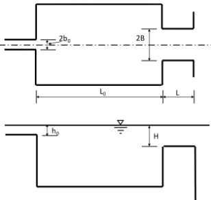
The idealized model of the experimental set up is as depicted in Figure 1. In this figure, all geometric variables of interest in the process are also identified.
Figure 1 - Schematic representation of the idealized model
2b0 2B
L0 L
H h0
T, temperature difference between the heated effluent and the receiving ambience, at the entrance to the strait was chosen as the independent variable representing the effect of the strait on the behavior of the heated effluent issued into the restricted bay. The variables that may contribute to the behavior of the effluent are listed in Table 1.
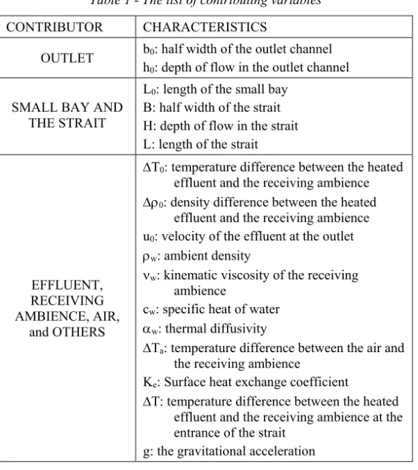
Table 1 - The list of contributing variables
CONTRIBUTOR CHARACTERISTICS
OUTLET b0: half width of the outlet channel h0: depth of flow in the outlet channel SMALL BAY AND
THE STRAIT
L0: length of the small bay B: half width of the strait H: depth of flow in the strait L: length of the strait
EFFLUENT, RECEIVING AMBIENCE, AIR,
and OTHERS
T0: temperature difference between the heated effluent and the receiving ambience 0: density difference between the heated
effluent and the receiving ambience u0: velocity of the effluent at the outlet w: ambient density
w: kinematic viscosity of the receiving ambience
cw: specific heat of water w: thermal diffusivity
Ta: temperature difference between the air and the receiving ambience
Ke: Surface heat exchange coefficient
T: temperature difference between the heated effluent and the receiving ambience at the entrance of the strait
g: the gravitational acceleration The following functional form, thus, can be formed.
∆T = f (b , h , L , B, H, L, ∆T , ∆ρ , u , ρ , ν , α , c , ∆T , K , g) (1) Employing Buckingham’s Theorem one obtains
∆ ∆ = f (Fr , Fr, Re, Pr, , ∆ ∆ , , , , ( ) , , ) (2)
where Frd is the Densimetric Froude Number at the outlet defined as Frd=u0/(0gh0/w); Fr is the Froude Number at the outlet defined as Fr=u0/(gh0)1/2; and Re is the Reynolds Number at the outlet defined as Re=u0(h0b0)1/2/w; Pr is the Prandtl Number in the bay defined as Pr=w/w.
The effects of Fr, Re, and Pr may be neglected (29). Furthermore, since u0 and Ta are kept constant and L0>>h0 throughout the experiments, the effects of Ke/0cwu0, Ta/T0, h0/b0, H/B, and h0/B will be insignificant and may also be disregarded. Therefore, Equation 3 reduces to
∆
∆ = f (Fr , ,
( )
, ) (3) At this step, in order to emphasize the presence of the strait a new parameter is introduced; the ratio of the nominal cross-sectional area of the effluent at the location of the inlet in the absence of the strait to the cross-sectional area of the strait. The representative depth hmax and half width yc are reported to be
hmax (h0b0)1/2Frd (4) and
yc L0 Frd-1/4 (5) as given by Harleman (10) and Jen et. Al. (11). Thus, the new parameter, area restriction parameter Ar is defined as
A =( ) (6) coupling equations 3 and 6 and considering that Ar is a combination of Frd, (h0b0)1/2/L0 and h0b0/HB; equation 3 becomes
∆
∆ = f A , ,( ) (7)
Once the functional relationship, of Equation 7, that can be used in investigating the effect of restriction imposed by a strait on the behavior of a heated effluent was established, an experimental setup was designed to facilitate the observation of the aforementioned effects of the strait on the behavior of the heated effluent.
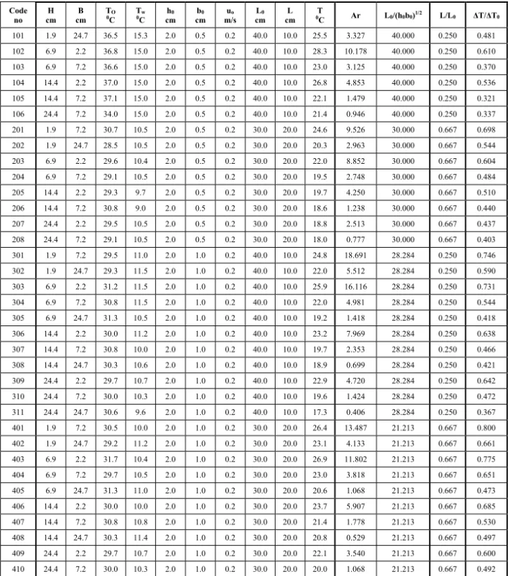
The experiments were carried out using several different combinations of geometric variables. The characteristics of the experiments run are listed in Table 2. In this Table, T0, Tw, and T are temperatures measured at the outlet, at the small bay, and at the inlet of the strait, so that T0=T0-Tw and T=T-Tw. In Table 2, the respective values of the variables appearing in Eqn. 7 are also included.
Table 2 - Observed and reduced values of the variables involved Code no H cm B cm TO 0C Tw 0C cm h0 cm b0 m/s uo cm L0 cm L 0TC Ar L0/(h0b0)1/2 L/L0 ΔT/ΔT0 101 1.9 24.7 36.5 15.3 2.0 0.5 0.2 40.0 10.0 25.5 3.327 40.000 0.250 0.481 102 6.9 2.2 36.8 15.0 2.0 0.5 0.2 40.0 10.0 28.3 10.178 40.000 0.250 0.610 103 6.9 7.2 36.6 15.0 2.0 0.5 0.2 40.0 10.0 23.0 3.125 40.000 0.250 0.370 104 14.4 2.2 37.0 15.0 2.0 0.5 0.2 40.0 10.0 26.8 4.853 40.000 0.250 0.536 105 14.4 7.2 37.1 15.0 2.0 0.5 0.2 40.0 10.0 22.1 1.479 40.000 0.250 0.321 106 24.4 7.2 34.0 15.0 2.0 0.5 0.2 40.0 10.0 21.4 0.946 40.000 0.250 0.337 201 1.9 7.2 30.7 10.5 2.0 0.5 0.2 30.0 20.0 24.6 9.526 30.000 0.667 0.698 202 1.9 24.7 28.5 10.5 2.0 0.5 0.2 30.0 20.0 20.3 2.963 30.000 0.667 0.544 203 6.9 2.2 29.6 10.4 2.0 0.5 0.2 30.0 20.0 22.0 8.852 30.000 0.667 0.604 204 6.9 7.2 29.1 10.5 2.0 0.5 0.2 30.0 20.0 19.5 2.748 30.000 0.667 0.484 205 14.4 2.2 29.3 9.7 2.0 0.5 0.2 30.0 20.0 19.7 4.250 30.000 0.667 0.510 206 14.4 7.2 30.8 9.0 2.0 0.5 0.2 30.0 20.0 18.6 1.238 30.000 0.667 0.440 207 24.4 2.2 29.5 10.5 2.0 0.5 0.2 30.0 20.0 18.8 2.513 30.000 0.667 0.437 208 24.4 7.2 29.1 10.5 2.0 0.5 0.2 30.0 20.0 18.0 0.777 30.000 0.667 0.403 301 1.9 7.2 29.5 11.0 2.0 1.0 0.2 40.0 10.0 24.8 18.691 28.284 0.250 0.746 302 1.9 24.7 29.3 11.5 2.0 1.0 0.2 40.0 10.0 22.0 5.512 28.284 0.250 0.590 303 6.9 2.2 31.2 11.5 2.0 1.0 0.2 40.0 10.0 25.9 16.116 28.284 0.250 0.731 304 6.9 7.2 30.8 11.5 2.0 1.0 0.2 40.0 10.0 22.0 4.981 28.284 0.250 0.544 305 6.9 24.7 31.3 10.5 2.0 1.0 0.2 40.0 10.0 19.2 1.418 28.284 0.250 0.418 306 14.4 2.2 30.0 11.2 2.0 1.0 0.2 40.0 10.0 23.2 7.969 28.284 0.250 0.638 307 14.4 7.2 30.8 10.0 2.0 1.0 0.2 40.0 10.0 19.7 2.353 28.284 0.250 0.466 308 14.4 24.7 30.3 10.6 2.0 1.0 0.2 40.0 10.0 18.9 0.699 28.284 0.250 0.421 309 24.4 2.2 29.7 10.7 2.0 1.0 0.2 40.0 10.0 22.9 4.720 28.284 0.250 0.642 310 24.4 7.2 30.0 10.3 2.0 1.0 0.2 40.0 10.0 19.6 1.424 28.284 0.250 0.472 311 24.4 24.7 30.6 9.6 2.0 1.0 0.2 40.0 10.0 17.3 0.406 28.284 0.250 0.367 401 1.9 7.2 30.5 10.0 2.0 1.0 0.2 30.0 20.0 26.4 13.487 21.213 0.667 0.800 402 1.9 24.7 29.2 11.2 2.0 1.0 0.2 30.0 20.0 23.1 4.133 21.213 0.667 0.661 403 6.9 2.2 31.7 10.4 2.0 1.0 0.2 30.0 20.0 26.9 11.802 21.213 0.667 0.775 404 6.9 7.2 29.7 10.5 2.0 1.0 0.2 30.0 20.0 23.0 3.818 21.213 0.667 0.651 405 6.9 24.7 31.3 11.0 2.0 1.0 0.2 30.0 20.0 20.6 1.068 21.213 0.667 0.473 406 14.4 2.2 30.0 10.0 2.0 1.0 0.2 30.0 20.0 23.7 5.907 21.213 0.667 0.685 407 14.4 7.2 30.8 10.8 2.0 1.0 0.2 30.0 20.0 21.4 1.778 21.213 0.667 0.530 408 14.4 24.7 30.3 11.4 2.0 1.0 0.2 30.0 20.0 20.8 0.529 21.213 0.667 0.497 409 24.4 2.2 29.7 10.7 2.0 1.0 0.2 30.0 20.0 22.1 3.540 21.213 0.667 0.600 410 24.4 7.2 30.0 10.3 2.0 1.0 0.2 30.0 20.0 20.0 1.068 21.213 0.667 0.492
3. EXPERIMENTAL FINDINGS AND CONCLUSIVE REMARKS
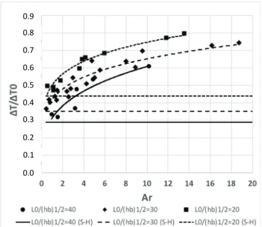
The recorded variation of dimensionless excess temperature difference, T/T0, at the inlet of the strait, with the area restriction parameter, Ar, is depicted in Figure 2. In this figure, dimensionless excess temperature differences, (T/T0)free, in the case of unrestricted receiving body of water at the respective locations as predicted by Stolzenbach-Harleman (S-H) are also included for the facilitation of comparison.
Figure 2 - Variation of heat built up at the inlet of the strait
Figure 3 - Variation of difference between the excess temperatures at respective locations for restricted and free receiving mediums
0.0 0.1 0.2 0.3 0.4 0.5 0.6 0.7 0.8 0.9 0.01 0.02 0.04 0.08 0.16 0.32 0.64
Investigation of the data reveals that the difference between the excess temperatures at the inlet of the strait for restricted and free receiving mediums, Δ(ΔT/ΔT0), defined as Δ(ΔT/ΔT0) = ΔT/ΔTo.-(ΔT/ΔTo)free, is strongly dependent on Ar, such that
Δ(ΔT/ΔT0) = ΔT/ΔTo.-(ΔT/ΔTo)free =0,11 ln(Ar) + 0.06 (8) as depicted in Figure 3.
The experimental findings strongly suggest that the excess temperature rise, Δ(ΔT/ΔT0), at the entrence of the restricting strait can be predicted once the Ar, the restriction parameter, is known.
Acknowledgement:
The author heartily acknowledges the effort of Mr. A. E. Nalbantoğlu who gathered the data used in this study. Thanks are also extended to Middle East Technical University which provided facilities for the experiments.
Symbols
Ar : Area restriction parameter B : Half width of the strait b0 : half with of the outlet channel cw : specific heat of water
Fr : Froude Number at the outlet Frd : Densimetric Froude Number G : the gravitational acceleration H : depth of flow in the strait
h0 : depth of flow in the outlet channel L : length of the strait
L0 : length of the small bay
Ke : Surface heat exchange coefficient Re : Reynolds Number at the outlet Pr : Prandtl Number in the bay u0 : velocity of the effluent at the outlet w : thermal diffusivity
Ta : temperature difference between the air and the receiving ambience
T0 : temperature difference between the heated effluent and the receiving ambience 0 : density difference between the heated effluent and the receiving ambience w : ambient density
w : kinematic viscosity of the receiving ambience
References
[1] Ryan, P. J., and Harleman, D. R. F., An Analytical and Experimental Study of Transient Cooling Pond Behaviour, R. M. Parsons Lab. for Water Resources and Hydrodynamics, Dept. of Civil Engineering, MIT, USA, Technical Report No. 161, 1973
[2] Adams, E. E., Stolzenbach, K. D., and Harleman, D. R. F., Near and Far Field Analysis of Buoyant Surface Jets, R. M. Parsons Lab. for Water Resources and Hydrodynamics, Dept. of Civil Engineering, MIT, USA, Technical Report No. 205, 1975
[3] Stefan, H., Dilution of Buoyant Two-Dimensional Surface Discharges, J. of Hydraulic Division, ASCE, Vol. 98, HY1, 71-86, 1970
[4] Stefan, H., Heated Dicharge from a Flume into a Tank, J. of Hydraulic Division, ASCE, Vol. 98, SA6, 1416-1432, 1970
[5] Turner, J. S., Buoyancy Effects in Fluids, Cambridge Univ. Press, 1973
[6] Policastro, A. J. and Tokar, J. V., Heated Effluent Dispersion in Lakes: State of the Art of Analytical Modelling Part 1: Critique of Model Formulation, Report No: ANL/ES-11, Aragone National Lab., 1972
[7] Stolzenbach, K. D. and Harleman, D. R. F., An Analytical and Experimental Investigation of Surface Discharges of Heated Water, R. M. Parsons Lab. for Water Resources and Hydrodynamics, Dept. of Civil Engineering, MIT, USA, Technical Report No. 135, 1971
[8] Nalbantoğlu, A. E., Hydro-Thermal Performance of Small Bays, Unpublished M.S. Thesis, Civil Engineering Dept., METU, May 1980
[9] Ger, A. M., Effects of Straits on the Behaviour of Heated Surface Jets, 20th Midwestern Mechanics Conf., Proc. 14b, West Lafeyette, Indiana, 1987
[10] Harleman, D. R. F., Thermal Stratification Due to Heated Discharges, International Symposium on Stratified Flows, Novosibirsk, 1972
[11] Jen, J. A., Wiegel, R. L., and Mobarek, I., Surface Discharge of Horizontal Warm Water Jets, Proceedings, ASCE, Power Division, 1966