OVERHANGS IN STRUCTURAL SYSTEMS AND EARTHQUAKE BEHAVIOUR FROM TORSIONAL IRREGULARITY POINT OF VIEW
1Hasan Hüsnü KORKMAZ
1 Selcuk University, Engineering Faculty, Civil Engineering Department, Konya, Turkey
(Geliş/Received: 11.07.2017; Kabul/Accepted in Revised Form: 28.12.2017)
ABSTRACT: Earthquake behaviour of structural systems strongly depends on geometry of the building.
The seismic motions can create unpredictable displacements and corresponding structural members may be forced more than that was evaluated. Torsional response of structures is very important for earthquake resistant design philosophy. In this study, overhangs in buildings and their effect on torsional displacements under seismic forces was evaluated. The model building has 5 different overhang alternatives and 3 different overhang lengths. Structural systems were modelled in a finite element packed program ETABS and investigated under response spectrum analyse cases. Mode superposition method used for determination of dynamic properties. Effect of cantilever overhangs in seismic response were evaluated.
Key Words: Earthquake, Earthquake code, Irregularity, Overhangs, Torsional response
Yapı Sistemlerinde Konsol Çıkmalar ve Burulma Düzensizliği Açısından Deprem Tepkisine Etkileri ÖZ: Yapıların deprem performansı ilk olarak binanın geometrisine bağlıdır. Sismik yüklemeler binada
tahmin edilemeyen deplasmanların oluşmasına ve yapı elemanlarının hesaplanandan daha fazla zorlanmasına yol açabilir. Depreme dayanıklı yapı tasarımı içinde burulma düzensizlikleri çok önemlidir. Bu çalışmada binalarda bulunan çıkma konsollar ve bunların yapının deprem dayanımına olan etkisi incelenmiştir. Bu amaçla, 5 değişik çıkma konfigürasyon alternatifi ve 3 farklı konsol boyu parametre olarak seçilmiştir. Model binalar ETABS programında modellenerek, “response spektrum” analizi gerçekleştirilmiş ve sismik analiz yapılarak, konsol ve çıkmaların etkisi incelenmiştir.
Anahtar Kelimeler: Deprem, Deprem yönetmeliği, Düzensizlik, Konsol çıkma, Burulma,
INTRODUCTION
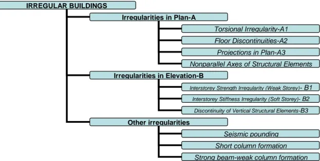
In Turkish Earthquake Code (TEC, 2007), second chapter gives the definition of irregular buildings, limits and enforcements about irregularities. In this chapter, structural systems are classified as regular or irregular. Irregularities may include plan (horizontal direction) or vertical arrangements. The code advise to avoid irregularities in preliminary design stage and states that seismic behaviour of irregular buildings are unfavourable. From previous earthquakes, it is known that, irregularities decreases the earthquake performance of structural systems. (Mendi, 2005). The code states that, geometry of the building may become a negative factor for seismic resistance. In the code, irregularities are defined under two main headings, in plan (A) or in elevation (B). Irregularities in plan divided to; torsional irregularity, floor discontinuities, projections and non-orthogonal structural layouts (Ozmen and Unay 2007). Besides, irregularities in elevation includes, stronger beam-weaker columns, captive columns, and earthquake hammering effects (Figure 1) (Tezcan, 1998).
Figure 1. Irregularities defined in the Turkish Earthquake Code (TEC, 2007)
Earthquake code also defines what the designer do if there exist irregularities in the structure (Mendi, 2005). If there is A1 and B2 type irregularity, then, seismic analysis type is dictated by the code. If there is A2 and A3 type irregularity, the designer must prove that, floor system can transfer seismic loads safely.
MATERIALS AND METHODS
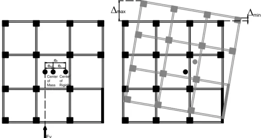
During the seismic analyses, two orthogonal directions are assumed to be exist. Under lateral earthquake forces, displacements of column bottom and top joints are calculated (i) (Figure 2). Storey
drift is calculated as the difference of joint displacements of two consecutive floor levels and defined as
i=(i)-(i-1) (1)
During the application of lateral forces, %5 eccentricities must be taken into account. In two orthogonal directions. The minimum (imin) and maximum (imax) floor drifts are calculated and the mean storey
drift is calculated as;
i-ave=((imax)+ (imin))/2 (2)
bi) can be determined as the ratio of maximum relative drift to the
average drift at the same story. Both values must be calculated at the same direction
bi=(imax)/( i-ave) (3)
In the case of buildings torsional irregularity value, bi exceeds the value of 1.2, then, it is said that type
A1 irregularity exist in building. If this value is between 1.2 and 2, then the additional eccentricity is increased and the solution is repeated. The eccentricity amplification (Di), factor is defined as;
Di=(bi/1.2)2 (4)
IRREGULAR BUILDINGS
Irregularities in Plan-A Irregularities in Plan-A
Irregularities in Elevation-B
Interstorey Strength Irregularity (Weak Storey)- B1
Other irregularities
Torsional Irregularity-A1 Floor Discontinuities-A2 Projections in Plan-A3
Interstorey Stiffness Irregularity (Soft Storey)- B2 Discontinuity of Vertical Structural Elements-B3
Seismic pounding Short column formation Strong beam-weak column formation Nonparallel Axes of Structural Elements
Now the design eccentricity (ed) becomes
ed=e+0.05x Di (5)
If the torsional irregularity factor exceeds value of 2 then, the structural system must be revised or changed and the analyses must be re-performed. At that point, it is very important for the designers that, torsional irregularity is an unwanted situation. Although code gives several penalties for this case, it is better to avoid torsional movements. Code just warns designers about the adverse effects of unpredictable movements in the structure (Dukkal, 2007). There is no any dynamic amplification in TEC-2007 for torsional responses (Inel et al., 2008). In several documents dealing with post earthquake reports, devastating effects of torsional effects are reported (Gulay and Calim, 2003).
Center of Mass Center of Rigidity es ead ed Ey
max
minFigure 2. Calculation of maximum and minimum storey drifts
If there is a torsional irregularity, then the seismic analysis method must be dynamic analysis type and equivalent earthquake loading method must be avoided. (Tezcan and Alhan, 2008). The resistance point of structure to the lateral loads is center of rigidity. The seismic loads are assumed to be applied to the center of mass. The distance between these two points creates rotational movements and extra force or moments to the structural members. Especially additional shear forces can create unpredictable failures in the structure. The modification of center of mass is difficult since it depends on geometry. Designer can change the center of rigidity by changing the structural system (Ozmen and Unay 2007).
Plan Geometry and Torsional Irregularity
Building plan geometries and torsional response relationships were investigated using finite element models (FEM) of the selected structural systems. Cases involving cantilever projections or overhangs was evaluated within the study. The generated 3D models were analysed under lateral earthquake loadings and the results were compared in terms of their earthquake behaviour based on torsional irregularity and with the help of the graphics.
Overhangs and Torsional Responses
Open or closed cantilever projections are a form of irregular mass distribution commonly encountered in the Turkish urban pattern to enlarge plan dimensions and create space for balconies (Ozmen and Unay 2007). Cantilevered facades are also fashionable for architectural and aesthetic reasons. The majority of RC-framed buildings in Turkey have overhangs after their ground storeys due
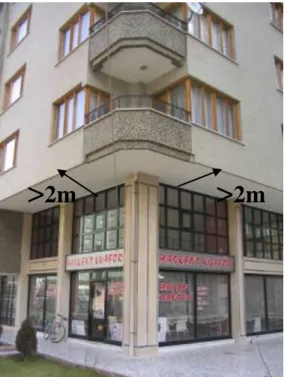
to public improvement laws and a lack of building lots. Because city municipalities limit a building’s first-storey footprint-to-plot ratio, cantilever projection construction in the form of beams or block joist floor (hollow-tile floor slab) framing is often employed at the second-floor level. Public improvement laws permit land developers to cover more area on upper floors than on the ground floor. The aim of cantilever projections is thus to maximise the gross floor area of a building by utilising the land in the most effective manner. However, this practice can have negative effects on seismic behaviour. In Turkey, the cantilever length is commonly approximately 1.5 m, while in some cases it can be 2 m or more at the first floor level, as shown in Figure 3.
Figure 3. Long, heavy overhangs over a soft storey formation
The problems related to cantilever overhangs include the following.
If overhangs are not located on the central axis of a building, they will create torsional irregularities and their lateral rigidity will differ from that of the floors below or above.
The mass centre of the structure is far from the ground. Heavy overhangs shift the buildings mass centre upwards and remove it from the centre of rigidity.
Under earthquake motion, closed projections in particular will experience critical displacements, which may lead to a partial collapse.
The final problem is related to the vertical direction of earthquakes. Many buildings with large, heavy overhangs have been damaged when subjected to the vertical component of an earthquake (Ozmen and Unay 2007; Inel et al., 2008).
If cantilever projections are to be made, the beams should be continuous under the cantilevered slab. Past earthquakes have revealed that buildings with heavy overhangs are more susceptible to damage, and some buildings have been severely damaged due to long, heavy cantilevers beginning on the second floor level. During the 1999 Marmara and 2003 Bingol earthquakes in Turkey, it was observed that buildings with heavy overhangs and balconies sustained heavier damage than those with regular elevations.
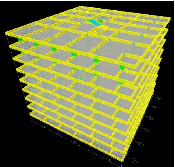
Six different 9-storey structural models, including the reference building, were modelled to investigate the relationship between cantilever projection and the consequences of earthquakes (Figure 4). The reference structure was a typical moment-resisting, beam–column dominated RC frame, which is the
>
2m
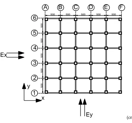
most common seismic framing system used in Turkey for building construction. The reference structure was an ordinary building with the floor plan shown in Figure 5. The reference model’s frame measured 25 m by 25 m in plan and had 5@5 m bays in both the X and Y directions. The floor plans were identical in all storeys.
Figure 4. Finite element model of the model structure
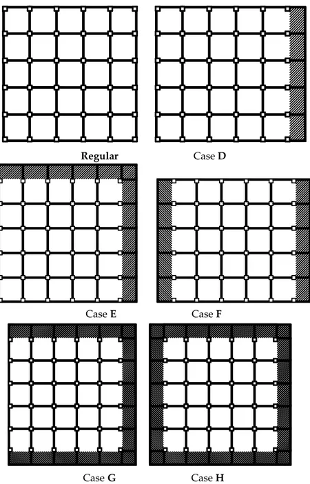
The first model, or reference model, did not contain a cantilever projection and was named the “Regular Frame”. The second model (Case D) contained an overhang along the one side, while Case E had were two projections on adjacent sides. Case F also contained two projections, but on two opposite sides. Three and four cantilevers were attached to the regular frames in Cases G and H, respectively. The model identifiers are provided in Figure 6. The generated models did not contain any code-defined irregularities such as weak or soft storeys (B1-B2), floor discontinuities (A2), projections in plan (A3) or nonparallel axes.
Three-dimensional mathematical models were created using the ETABS finite element program to carry out separate linear dynamic analyses in the longitudinal and transverse directions. During the dynamic analysis, square root sum of squares-SRSS combination method is prefferred since the regular building plan was chosen as symmetric, SRSS method would be suitable. The dynamic analysis are very important for irregular buildings. The irregularity may result in more complex response than the assumed behaviour. The columns were designed to be square for simplicity. As stated above, the reference model building did not contain overhangs, but the other models contained overhangs with various configurations. The columns in the model are square columns and contained %1 amount of steel, which was the minimum amount in the Turkish reinforced concrete code.
500 500 500 500 500 500 500 500 500 500
x
y
A
B
C
D
E
F
6
5
4
3
1
2
Ex
Ey
(cm)Figure 5. Reference model of a moment-resisting frame DISCUSSIONS
The proper representation of building stock was the primary concern in the design and detailing of the model buildings. Because the majority of Turkish buildings were constructed according to the 1975 Turkish Earthquake Code, the selected model buildings were designed according to this code and considering vertical gravity loads. The vertical loads consisted of live and dead slab loads, infill wall loads on beams and the dead loads of columns and beams. The total gravity load was calculated as 1.4 times the dead load (G) plus 1.6 times live load (Q). To prevent creep failure, the Turkish Reinforced Concrete Code (TS500, 2000) dictates that, the capacity of a column (Acxfck) must be at least twice that of
the load calculated using the 1.4G+1.6Q load combination. Here, G is the dead load and Q is the live load acting on the columns’ tributary area. Note that the storey weight consists of the dead load and 30% of the live load (for residential buildings according to TEC-2007) at the time of the earthquake.
A concrete strength of 15 MPa was selected even though the minimum concrete class given in the TEC-2007 is 20 MPa, and the reinforcement ratio of the columns was set at 1.5%. The uniform slab gravity loads were 2.5 kN/m2 for the dead load case and 3 kN/m2 for the live load case. The dead load of
the infill walls was assigned as uniformly distributed loads on the beams. The thickness of the exterior infill walls was 200 mm, considering the window openings, while the thickness of the interior walls was 100 mm. The thickness of the slab was 150 mm and the typical floor height was set at 3 m. The beam cross-sections were assumed to be T-shaped for the interior beams and L-shaped for the exterior beams. All beams had 200 mm cross-sectional widths.
Regular Case D
Case E Case F
Case G Case H
Figure 6. Model identifiers for cases with heavy overhangs
The column and beam dimensions used in this study were typical frame element proportions present in the existing Turkish building stock. Analyses were carried out using the gross section properties of the concrete elements. No effort was made to create a strong column–weak beam system because such systems were not considered in the 1975 version of the Turkish Earthquake Code. All structural members were placed orthogonally with continuous framing. The building was assumed to have 5% damping in all of its deformation modes (Tezcan and Alhan, 2008; Inel et al.,2008)
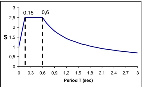
The columns were modelled with frame members, while the slabs were modelled with shell elements and meshed. These slabs were assumed to be infinitely rigid and rigid diaphragms were assigned. The beams were also meshed to ensure that the beam mesh points and slab mesh points coincided. Foundations were not considered, and fixed supports were assumed at the base of each building. Seismic analyses were carried out in accordance with the recently published Turkish Earthquake Code (TEC, 2007). Four different soil types were defined in TEC-2007. This study used the Z3 type soil class. The Z3 type soil class has characteristic spectrum periods of Ta=0.15 sec and Tb=0.6 sec
design ground acceleration of Ao in the first seismic zone (or regions of high seismicity) and the importance factor, I, was set equal to 1.0 (for residential and office buildings, hotels, building-like industrial structures, etc.). Because the structures were assumed to be designed according to the 1975 version of the Turkish Earthquake Code, the structural behaviour factor, R, was set equal to 4 for reinforced concrete moment resisting frames of nominal ductility. An additional accidental eccentricity of 5% was applied even when the existing eccentricity of the structure was zero, as dictated by TEC-2007.
0,6
0,15
0 0,5 1 1,5 2 2,5 3 0 0,3 0,6 0,9 1,2 1,5 1,8 2,1 2,4 2,7 3 Period T (sec)S
Figure 7. Spectrum curve for the Z3 soil type (TEC, 2007)
For models with overhangs, the beams connecting the exterior columns (Figure 8) were shifted to the tips of the cantilever beams, which were extended from the exterior column to the external face of the cantilever. In exterior columns, the cantilever beams extended from the column’s top joint to the cantilever’s external face (Beam 1 or Beam 2 in Figure 8). This beam application is common in Turkish residential buildings, where beams are hidden at the tops of exterior brick infill walls.
External Column Corner Column Beam2 Beam1
Shifted ExternalFace of Cantilever
Cantilever Beam Overhang O v e rh a n g a) b)
Figure 8. Exterior beam configuration at the building corner
(a-without overhangs, b-with two adjacent overhangs)
The infill wall loadings were relocated on the beams surrounding the overhang portion. The cantilever length was also a parameter and set at L=1 m, 2 m or 3 m. Cantilevers more than 3 m long are not
common in practice, but this case was analysed to represent an extreme condition. The earthquake definitions (mode superposition) were applied in two orthogonal directions along the X and Y global axes. A dynamic analysis was performed and the joint drifts were determined. Torsional irregularity factors were calculated for every floor and the maximum values are represented in Figure 9, which also illustrates the code limit of 1.2. This graph clearly shows that the code limit was exceeded for Cases D and G at every cantilever length. In Case E, on the other hand, the limit value was exceeded for the 3-m cantilever length. The torsional irregularity factors were below the code limit in Cases F and H.. Although the reference model structure was a regular, symmetric building, the cantilevers disturbed its torsional stability in every case except for Case F. This result was quite logical because the overhangs on the opposite sides balanced the structure (Korkmaz and Korkmaz, 2013).
0,95 1 1,05 1,1 1,15 1,2 1,25
Regular Case D Case E Case F Case G Case H
T o rs io n a l Ir re g u la ri ty F a c to r (
bi ) L=3m L=2m L=1mFigure 9. Torsional irregularity factors for cantilever projection cases
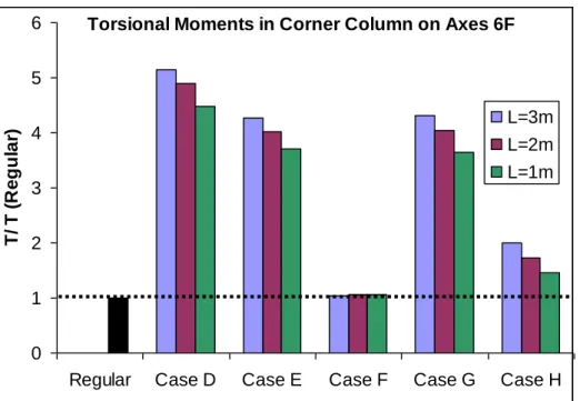
The maximum torsional moment due to the lateral earthquake loadings occurred in the corner column on the 6-F axes, and is investigated in Figure 10. The obtained torsional moments were normalised by dividing them by the corresponding moment obtained from the regular case. The torsional moments were increased in all cases except Case F. Cantilever length had a significant effect on torsional moments. As the cantilever length increased, the torsional moments also showed an increasing trend. The inferior situations were Cases D, E and G, while Case F displayed similar results to the regular case. The torsional moments in Case D were approximately 5 times higher than those in the regular case, while those in Cases E and G were 4 times higher and those in Case H were 2 times higher.
Torsional Moments in Corner Column on Axes 6F 0 1 2 3 4 5 6
Regular Case D Case E Case F Case G Case H
T / T ( R e g u la r) L=3m L=2m L=1m
Figure 10. Torsional moment ratios for the cantilever projection cases with respect to the regular case CONCLUSIONS
In this paper, architectural plan geometries and torsional responses were evaluated using 3D finite element models of selected structural models that reflected the existing residential building stock in Turkey. The basic reference structure had a square plan geometry and contained no soft or weak irregularities or projections in plan, nor did the models include elevation irregularities, floor discontinuities or discontinuities in vertical structural elements. The span lengths were 5 m and there were 5 spans in the X and Y directions. The storey height was 3 m throughout all the buildings. The columns were designed as square and the dimensions of the all columns were identical within each storey, while the column sizes were altered as the number of storeys was increased. The column dimensions are determined according to the load level in dead load case. Under dead and live load combination (1.4xDead+1.6xLive), the column forces (F) must be half of the columns axial load carrying capacity (F<(0.5)xFcap). The first case examined the effects of cantilever projections or overhangs, which are very common in the Turkish residential building stock, on the torsional response of a structure. A set of 6 models, including a reference model, was analysed for orthogonal earthquake directions. The mode superposition method was used to evaluate the earthquake response of each model. The overhang configurations of one overhang (Case D), two overhangs (Cases E and F), three overhangs (Case G) and four overhangs (Case H) were considered. The overhang length was also a parameter, with 1 m, 2 m, and 3 m overhang lengths considered. The maximum and minimum storey drifts were calculated and the torsional irregularity factors (bi) were determined. Although the torsional irregularity factor of the
reference building with no overhangs was 1.06, the bi values for Case D (one overhang) and Case G
(three overhangs) exceeded the code limit of 1.2 for all overhang lengths. In Case E (two overhangs on adjacent sides), this limit was also exceeded for overhang lengths of 2 m and 3 m. In Case H (four overhangs), the bi values fell below the limit of 1.2. A superior response was obtained in Case F (two
overhangs on opposite sides) and its bi values were nearly equal to those obtained for the reference
model. The code upper limit of 2 was never exceeded in any case. The inferior performance obtained in Cases D and G could be attributed the fact that the symmetry of the floor had been disturbed. Although
bi values remained below the code limit because symmetry
existed. The overhang length also had effects on the torsional response and was more pronounced in Cases D and E. The torsional moments in the corner columns due to earthquake loadings were also
calculated and compared, and those on the corner column in Case D was approximately 5 times, those in Cases E and G were 4 times, and that in Case H was 2 times higher than the torsional moment of the reference regular case with no overhangs. The torsional moment in the corner column of Case F remained approximately constant. This study was conducted to illustrate the importance of building geometrical properties, architectural design decisions and their consequences in earthquake responses, and to remind both civil engineers and architects that earthquake-resistant structural design is a common responsibility that must be shared. More numerical analysis must be done to account for soft storeys, short column effects and architectural design.
Symbols
I: displacements of column bottom and top joints i-ave:Average story drift
imax,
imin:Maximum and minimum story drifts bi: Factor for torsional irregularityDi,: The eccentricity amplification factor
ed: Design eccentricity
REFERENCES
Duggal S.K., 2007, Earthquake Resistant Design of Structures, UK: Oxford University Press, London, UK. Gulay, F.G., Calim, G., 2003, “A Comparative Study of Torsionally Unbalanced Multi-Storey Structures
Under Seismic Loading”, Turkish Journal Engineering Environment Science, Vol. 27, pp. 9-11. Inel, M., Ozmen, H.B., Bilgin, H., 2008, “Re-evaluation of Building Damage During Recent Earthquakes
in Turkey”, Engineering Structures, Vol. 30, pp. 412–427.
Korkmaz, S.Z., Korkmaz, H.H., “Seismic Design Considerations about Architectural Design Aspects and Irregularities”, Proceedings of the World Congress on Advances in Structural Engineering and Mechanics (ASEM13), Korea, 2013.
Mendi, H.E., 2005, Evaluation Of Architectural Consciousness And Exploration Of Architecture-Based Issues In Seismic Design, MSc Dissertation, Middle East Technical University, Ankara.
TEC-2007, Turkish Earthquake Code, Specification for Buildings to be Built in Seismic Zones, Ministry of Public Works and Settlement, Ankara, 2007.
Tezcan, S., Alhan, C., 2008, “Parametric Analysis of Irregular Structures under Seismic Loading According to the New Turkish Earthquake Code”, Engineering Structures, Vol. 23, pp. 600–609. Tezcan, S., 1998, An Architect’s Log Book for Earthquake Resistant Design, Turkish Earthquake Foundation
Press, Istanbul, Turkey.
TS500-2000, Turkish Reinforced Concrete Code, Turkish Standarts Institue., Ankara, 2000.
Ozmen, C., Unay, A.I., 2007, “Commonly Encountered Seismic Design Faults due to the Architectural Design of Residential Buildings in Turkey”, Building and Environment, Vol. 42, pp. 1406–1416.