1Ж8І-ОМ ÄNB OF /•.Ϊί. OBJECT - GHîHNTED EBFE'JJT SYîiTSvI 31£ЕіД,·
УУШЯіТ« Α'·;·άί-ϊ-<^νί-ί4 Ϊ-Ο' .ítX'íüj scr«í^r^<-:í'^ ШІЛЗІШ*·. ÜH2YEE-0Î1‘· l ^ -,■ ·_Γ^'/;ν>Γΐ< *f ·. -,'.··'■·> ií’H:?: г braiiïi 22ökfa /¿{йгоУ'·'
‘ía;-S
T 6 : ? í j/9 S 9
DESIGN AND IMPLEMENTATION OF AN
OBJECT-ORIENTED EXPERT SYSTEM SHELL
A THESIS
SUBMITTED TO THE DEPARTMENT OF COMPUTER ENGINEERING AND
INFORMATION SCIENCES
AND THE INSTITUTE OF ENGINEERING AND SCIENCE OF BILKENT UNIVERSITY
IN PARTIAL FULFILLMENT OF THE REQUIREMENTS FOR THE DEGREE OF
MASTER OF SCIENCE
By
Ismail HakkiToroslu
June 19S9
I Í-4-C^LL
i
'Tc/’oilt4
tarafiadan bagislanmigtir.
Q A *ν\.*ϊ
т ь і ч
I certify tlicit I have read this thesis and that in my opinion it is fully adequate, in scope and in quality, as a thesis for the degree of Master of Science.
( S Â m u T )
Asst. Prof. Dr. Halil jOt.aj- GÜVENİR (Principal Advisor)
I certify that I have read this thesis and that in my opinion it is fully adequate, in scope and in quality, as a thesis for the degree of Master of Science.
I certify that I have read this thesis and that in my opinion it is fully adequate, in scope and in equality, as a thesis for the degree of Master of Science.
Prof. Dr. David Davenport
Approved for the Institute of Engineering and Science:
ABSTRACT
DESIGN AND IMPLEMENTATION OF AN
OBJECT-ORIENTED EXPERT SYSTEM SHELL
Ismail HakkıToroslii
M.S. in Computer Engineering and
Information Sciences
Supervisor: Asst. Prof. Dr. Halil Altay GÜVENİR
June 1989
Expert systems represent a new opportunity in computing. An expert sys tem is a computing system capable of representing and reasoning about some knowledge-rich domain with a view to solving problems and giving advice. Expert system shells are developed to create expert systems in an easy way. In recent years the object-oriented paradigm has been developed. The object- oriented approach has many advantages such as data abstraction, program modularity, and structural data representation. Therefore, we are developing an expert system shell which stores knowledge and data in object-oriented style. Also, an object-oriented DBMS part of our shell satisfy the needs of several expert systems rec|uiring large base of fcvcts. Such shells can be used to build expert systems by only adding the domain-specific knowledge.
Keywords: Expert system, e.xpert system shell, knowledge representation, object-oriented approach.
ÖZET
NESNESEL UZMAN SİSTEM KABUĞU TASARIM VE
GERÇEKLEŞTİRİMİ
İsmail HakkıToroslu
Bilgisayar Mülıendisliği ve Enformatik Bilimleri Yüksek Lisans
Tez Yöneticisi: Yrd. Doç. Dr. Halil Altay GÜVENİR
Haziran 1989
Uzman sistemler bilgisayar bilimlerinde yeni bir konu olarak ortaya çık mıştır. Uzman sistemler bilgi yoğun sistemlerin geliştirilmesinde kullanılan yazılım sistemleri olarak tanımlanabilir. Uzman sistem kabukları da uzman sistemlerin kolayca geliştirilebilmeleri için ortaya çıkmıştır. Son yıllarda yeni bir yazılım tekniği olarak ortaya çıkan nesnesel yaklaşım birçok üstünlüklere sahiptir. Bunlardan en önemlisi nesnesel yaklaşımın insanın düşünme tarzına yakın olmasıdır. Bu nedenle, bizim de geliştirmekte olduğumuz uzman sis tem kabuğunda bilgilerin saklanması için nesnesel yaklaşım teknikleri kul lanılmıştır. Sistemimizin bir parçası olan nesnesel veri tabanı büyük bilgi ta banını gerektiren uzman sistemlerin geliştirilmesine de olanak sağlamaktadır. Anahtar Kelimeler: Uzman sistem, uzman sistem kabuğu, bilgi gösterimi, nesnesel yaklaşım.
ACKNOWLEDGEMENT
I would like to thank Asst. Prof. Dr. H. Altay Güvenir, who is the supervisor of this thesis, because of his valuable help, remarks and advising this interesting thesis subject.
TABLE OF CON TEN TS
1 IN T R O D U C T IO N 1
2 E X P E R T SYSTE M S 4
2.1 Types of Expert Systems ... 5 2.2 Components of Expert S ystem s... 6 2.3 Construction of Expert Systems... 8
3 E XP E R T SY ST E M SHELLS 9
3.1 Basic Properties of Expert System T o o ls ... 9 3.2 Some Examples of Expert System T o o l s ... 10
4 K N O W L E D G E REPR ESEN TATIO N MODELS 14
4.1 Production R u le s ... 14 4.2 Frames... 17 5 O B JE C T -O R IE N TE D A P P R O A C H 20 5.1 Ba.sic C oncepts... 20 5.2 Object Identity... 22 6 T H E OES SY ST E M 24 vi
6.1 Unification of Expert and Database Systems Using
Object-Oriented A pp roach... ... . 24
6.2 DBMS Part of the O E S ... 26
6.3 Inference Engine Part of O E S ... 38
6.3.1 Knowledge Representation Language of O E S ... 38
6.3.2 Control Structure of O E S ... 41
6.4 Implementation of O E S ... 45
7 C O N C LU SIO N 48 A P P E N D IC E S 54 A S Y N T A X OF TH E K N O W L E D G E REPR ESEN TATIO N L A N G U A G E OF OES 54 B S Y N T A X OF TH E M E T H O D D E V E L O P M E N T L A N G U A G E OF OES 56 C A N E X A M P L E EXPER T SYSTE M IM P L E M E N T E D IN OES 59 C .l Knowledge Base of ADVICE ... 60
C.2 Some Part of the Database of A D V I C E ... 63
C.3 The Outputs of ADVICE for Some E x e c u tio n s ... 68
LIST OF FIGURES
2.1 Structure of an ideal expert sj'stem... 6
6.1 The structure of OES... 25
6.2 The main menu of OES... 26
6.3 The menu of the DBMS part of OES... 26
6.4 The class hierarchy for a simple expert system... 27
6.5 The menu of the DDL part... 27
6.6 The menu used for defining the properties of classes... 28
. 6.7 Definition of the instance variable “TAKES” of class “ COURSE.” 29 6.8 Definition of the instance variable “PREREQUISITES’” of class “ COURSE.” ... 30
6.9 Definition of the message “ COUNT” of class “COURSE.” . . 32
6.10 The menu of the DML part... 33
6.11 Creation of an instance of chess “STUDENT.” ... 34
6.12 Deletion of an instance of class “COURSE.” ... 35
6.13 Main control algorithm of OES... 42
6.14 Definitions of the classes of an example expert system. 43 6.15 Selecting a specific instance of cla.ss STUDENT... 44
6.16 Obtaining the results *)f the execution of the expert system. . 45 viii
1. IN T R O D U C T IO N
An expert system is a specicU kind of computer program that embodies the expertise of human experts in some specific domain. The behavior of an expert system is intended to be similar to that of a human expert in the specific field. This is the major difference of expert systems from conventional computer programs [24,15,10,33].
Another difference of expert systems from conventional computer pro grams is that their tasks usually have no algorithmic solutions or they must make conclusions based on incomplete information [13].
There are many tools for constructing expert systems ranging from general- purpose programming languages (e.g. LISP) to highly specialized tools (e.g. EMYCIN) [16]. Early expert systems are implemented with general-purpose programming languages. Earliest expert system tools such as EMYCIN are based on the past expert systems such as MYCIN [33]. Therefore, they were not general purpose tools. Today, there are several general-purpose expert system development tools such as OPS5 and ROSIE. Expert system shells can be viewed as new programming languages. Instead of the data objects in conventional languages such as integers and arrays, expert system shells maintain facts and rules. The control structure of expert system shells are also different from conventional languages. Conventional languages’ control structures consist of sequential execution, conditional statements and loops. However, in expert system shells rule-chaining and pattern mcitching are the basic control structures [33].
Many expert system applications require both the problem solving capa bility and the management of large database of facts. The organization of new tools suitable for these types of applications is one of the most important issues in Computer Science [24].
Object-oriented knowledge rci)rescntation model is used in several expert
systems, but there is no commercial expert system tool that has an object- oriented knowledge representation language [17,25,27]. Many expert systems and expert system shells provide database support in addition to their infer ence mechanisms [7,10,12,19,22,34]. However, these expert system tools are not suitable for all kind of expert system applications.
Each expert system application I’equires different properties. Some of them require very powerful database support, but for some expert system applications a simple database system or a static knowledge representation model may be enough, but they require numerical calculations or formu las. Therefore, the expert system shell must have all these properties to be a general purpose tool, and much research is being done on this subject [1,7,8,11,20,29,30,34].
Another important issue in expert system shells is the need for a high- level representation language for expressing the knowledge of human experts. The language should be readable, manageable and experts should be able to read and understand the rules easily. Among the present tools only a few has this property (e.g. R0SIE)[1G]. Therefore, we designed a high-level representation language for this implementation.
The goal of this research is to design a general purpose expert system shell which is able to maintain hvrge databases. An object-oriented approach is used for this reason. This implementation consists of two parts; object- oriented database management part is used to store large number of facts, and expert system shell pcirt is used to invoke the application of the rules. Because of its object-oriented style, we called our system O b ject-O rien ted E xp ert S ystem Shell (O E S ).
In the second chapter of this thesis, information about the expert systems is given. The basic properties, structures, type and the construction of the expert systems are explained in this chapter.
In the third chapter, expert system shells are defined and some well-known commercial expert system tools are introduced.
The fourth chapter defines the basic knowledge representation models used in expert systems. The.se models “production rules” and “frames” are defined and their advantages and disadvantages are discussed.
The fifth chapter gives the basic information about the object-oriented approach. Basic concepts of object-oriented approach and object identity
concepts are discussed in this chapter.
The sixth chapter is about the OES system. Its structure, knowledge rep resentation model and DBMS part are explained in detail. The user interface of OES is also explained in this chapter by examples.
2. EXPERT SYSTEM S
The term “knowledge-based systems” and “expert S
3
^stems” are used to de scribe the programs such as much knowledge embedded in the program and expert human methods are utilized to achieve expert-level performance [33].Expert systems differ from conventional computer programs because their tasks have no algorithmic solutions and because they must often make con clusions based on incomplete or uncertain information [13]. The structures of expert systems are modular. Facts and other knowledge of the domain can be separated from the inference engine which applies the general knowledge to the particular problem. With this separation, the program can be changed by simple modification of the knowledge base.
Basic reasons of why expert systems are used instead of conventional systems are as follows [15]:
• Many difficult and interesting problems do not have tractable algorith mic solutions.
ex-• Human experts achieve outstanding performance in their domain of
pertise, therefore if computer programs embody human experts’ knowl edge, then, they should attain high performance also.
• Knowledge is a scarce resource. Extracting knowledge from humans and putting it in computable forms reduce the cost of knowledge repro duction. This roi^roduction is done l^y making the knowledge available for public in expert systems.
Expert systems have some differences from conventional systems. The first basic difference of expert systems from the conventional systems is that expert systems perform difficult tasks at expert level of performance. Another
difference is that they include domain-specific problem solving strategies in stead of general but weak methods. The third basic difference of expert sys tems is thcit they provide explanations or justifications on their conclusions and on their inference processes. Because of those important differences of expert systems from the conventional systems, expert systems are defined as a new area in Computer Science.
2.1
Types of Expert Systems
Basically, expert systems can be classified into ten different types [15,32]. However, some expert system applications do not fit directly into one of those types, and they can have the properties of more than one of those types.
• Interpretation systems (c.g. speech understanding s}'’stem) analyze data to determine its meaning.
• Prediction systems (e.g. weather forecasting system) infer consequences from given situations.
• Diagnosis systems (e.g. medical diagnosis system) infer system mal functions from observable data.
• Design systems (e.g. circuit board design system) develop configura tions of objects that satisfy the constraint of the design problem. • Planning systems (e.g. exi:>eriment planning system) design actions that
can be carried out to achieve goals.
• Monitoring systems (e.g. monitoring system for air traffic) compare observations of features that seem crucial to successful plan outcomes. • Debugging systems (e.g. computer-aided debugging system for com puter iDi'ograms) prescribe remedies for malfunctions and include rec ommendations for correcting diagnosed problem. •
• Repair systems (e.g. computer maintenance system) develop and exe cute plans to administer a remedy for some diagnosed problem.
• Instruction systems (e.g. educiition system) diagnose and debug stu dent behavior.
• Control systems (e.g. l)u.siness management system) include interpret ing, i^redicting, repairing and monitoring system behaviors.
UGcR
Figure 2.1: Structure of an ideal expert system.
2.2
Components of Expert Systems
Most expert systems have similar structures. None of expert systems con tains all the components described here, but usually they have most of these components. An ideal expert system contains the following components [15] (Fig. 2.1): •
• A language processor. • A blackboard.
• A scheduler. • An interpreter. • A knowledge base. • A consistency enforcer. • A justifier.
A language processor is used for communication between the user and the expert system. This language is usually a restricted English-like language or other user interface facilities such as menus.
A blackboard is used to hold intermediate results. There are basically three types of decisions recorded on blackboard. The plan elements describe the overall steps of the current problem, including current plans, goals and problem states. The agenda elements include the actions waiting for the exe cution, that is the rules in the knowledge base which seem relevant to decision placed on the blackboard. The solution elements represent the candidate hy potheses and decisions generated by the system.
A scheduler is used to control the order of rule processing. The scheduler keeps the control of the agenda and determines the next action that will be executed.
An interpreter is used to execute the chosen agenda item by applying the corresponding knowledge base rule.
A knowledge base consist of facts and rules of the application domain. A consistency enforcer is used to adjust previous conclusions when new datci or knowledge alter their bases. The consistency enforcer tries to keep the knowledge base and datal^ase in an consistent form.
A justifier is used to exi)lain the system behavior. In general, the justi fier answers questions about why some conclusions was reached or how this conclusion was obtained by the system.
2.3
Construction of Expert Systems
There are five major stages in the evolution of an expert system [15]. They
C c in be explained shortly as follows:
1. Identification is the process of determining problem characteristics. During identification, the knowledge engineer and expert work together to identify the problem area and define its scope.
2. Conceptualization is the process of finding concepts to represent knowl edge. During conceptualization, the expert and the knowledge engineer find the key concepts, relations and information fiow characteristics of the problem.
3. Formalization is the process of designing structures to organize knowl edge. Formalization involves finding the formal representations cor responding to the key concepts and relations for some expert system tool.
4. Implementation is the process of formulating rules that embody knowl edge. During imi)lementation, the knowledge engineer combines and reorganizes the formalized knowledge to make it suitable to informa tion fiow characteristics of the problem.
3. EXPERT SY STE M SHELLS
Many tools are used in the construction of expert systems. Those tools range from general purpose languciges such as LISP to highly specialized expert system tools such as EMYCIN. Today, several general purpose tools are developed for the construction of expert systems. Those tools are called e x p e rt system shells (to o ls ). Expert system shells can be viewed as new programming languages. Instead of the data objects in conventional languages such as integers and arrays, expert system shells provide facts and rules. The control structures of expert system shells are also different from that of conventional languages. The control structure of conventional languages consist of sequentiid execution, conditional statements and loops. However, in expert system shells, rule-chaining and pattern matching are the basic control structures.
3.1
Basic Properties of Expert System Tools
The features needed in expert system tools depend on three things [16]: • The characteristic of the domain, which includes the form of data and
the structure of the problem.
• The characteristic of the approach to solving the problem, which in cludes the type of search, representation of knowledge and the form of the control.
• The desired characteristics of the expert system to be built, which in cludes the type of users and the method of extending the system.
The design cJf a tool for building an expert system involves many con siderations including generality, completeness, language features, database structui'es and control methods.
In the design of an expert system tool one of the most important con siderations is the need for a high-level representation language for expressing procedural knowledge [16]. If there is no such language, it becomes very dif ficult for the users to develop an expert system application or to extend an existing expert sj'^stem. The language should be readable and manageable. With only a little training, application domain experts should be able to read and understand the rules written in this language.
Another issue that must be considered in the design of the expert system tool is the structure of database. Capability of the tool for representing static knowledge is extremely important, because if the system is too restrictive, even very simple problems cannot be implemented with this tool.
3.2
Some Examples of Expert System Tools
This section describes eiglit different well-known commci'cial expert system tools: EMYCIN, KAS, EXPERT, 0PS5, ROSIE, RLL, HEARSAY-III, and AGE [16,3]. They are defined shortly and basic advantages and disadvantages of those tools are explained. The aim of this section is to give a general idea about the commercial expert system tools evnd their structures.
E M Y C IN
EMYCIN is a domain-indeix:ndent version of MYCIN, Since the MYCIN was developed for diagnosis, EMYCIN is most suitable for deductive prob lems including diagnosis. EMYCIN uses backward-chaining control strategy. Knowledge is re
2
:>resented as production rules in EMYCIN. EMYCIN’s great est strength is its very convcuiient environment and user interface for building an expert diagnostic system. Major limitation of EMYCIN is its constrained control structure.K A S
KAS is based on the PROSPECTOR, which is a consultation program de veloped for diagnosis prol:>lems in mineral exploration. In KAS data is rep resented in semantic-network form and procedural knowledge is represented
as probabilistic inference rules. Theie are liotli backward and forward chain ing control strategies in KAS. Binding of antecedent variables to be used in conseqxient actions is not permitted in KAS, therefore it cannot be suitable for some problems.
E X P E R T
EXPERT is a programming system developed for building consultation mod els based on classification problems. EXPERT evaluates its rules in an or dered manner. When more than one rule is applicable, the rule with the highest confidence is used. The major strength of EXPERT is that it is easy to rise and i^ermits the rapid development of a prototype model. However, it is not possible to develop some systems, especially those requiring extensive search.
OPS5
0PS5 is a rule-based programming language. Rules in 0PS5 are data-driven and operate on a single glolsal database. Conti'ol in 0PS5 is done by the recognize-act cycle, which is a simple loop in which rules with satisfied an tecedents are found, one is selected and its action is performed. Unlike EMYCIN, KAS and EXPERT models, the 0PS5 model does not have sophis ticated user interface and explanation facilities. However, 0PS5 is a general purpose tool, and it can be suitable for different types of applications.
ROSIE
ROSIE is a general purpose rule-based programming system suitable for a broad range of knowledge engineering applications. ROSIE has an English- like syntax which has the capability of the creation and manipulation of its database. ROSIE has 3-types of inference mechanisms: state driven, where the state of the system directly causes a rule to fire; goal driven, where backward-chaining is used to find rules that will verify predictions in the rule conditions; change driven, where a database change causes a rule to fire. The nicvin strength of ROSIE is its English-like syntax. This permits the user to write entirely readable code, even to those people unfamiliar
with programming. The English-like syntax speeds the task development process. A major weakness of ROSIE is its lack of accessibility to its own rules and control structure, and lack of facilities for database structure and construction.
RLL
RLL is a structured collection of tools to help the knowledge engineer con struct, use and modify expert systems. Its strength is its competence model of programming and its generality of data structures and algorithms. Its lack of a user friendly front end is the major limitation in developing the RLL model. All code had to be entered in a LISP-like format.
H E A R S A Y -III
HEARSAY-III is a domain independent programming facility for develop ing prototype expert systems. It was designed to help the user in develop ing methods for representing and applying knowledge to a chosen problem area. In HEARSAY-III, the blackboard is used by the prototype expert system to store and coordinate information about the domain, pEirtial solu tions, and current activities. Execution usually i-esults in the modification of blackboiird information. HEARSAY-III model lacks sophisticated facili ties for I/O , database construction, and explanation. The major strength of HEARSAY-III is its general-purpose control structure, which supports interaction among numerous sources of knowlcxlge. A major weakness of HEARSAY-III is its lack of a high-level representation language.
A G E
The AGE system is a tool for helping knowledge engineers design, build, and test different frameworks for expert systems. It provides an environment in which different representational and control techniques can be developed. The AGE model lacks useful facilities for I/O , database construction and explanation. A major strength of AGE is its flexibility of representation and its easy way for the user to api)ly the general control frameworks supplied by the system.
Five of the tools (EMYCIN, KAS, EXPERT, 0PS5, ROSIE) are varia tions of conventional rule-based systems and thus provide the IF-THEN rule as a basic building block. 0PS5 and ROSIE «are general-purpose tools that provide greater flexibility of control and representation than do EMYCIN, KAS or EXPERT. The other tools (HEARSAY-III, AGE and RLL) are general-purpose systems for experimenting with expert system architecture. HEARSAY-III provides blackboard framework with cooperating knowledge sources as the basic design p«aradigm. AGE provides both a blackboard and backward-chaining paradigms. RLL provides a unit representation for both I'ules and facts.
Because of the restricted specialized structures in EMYCIN, KAS, and EXPERT, it is difficult to represent static knowledge(database) including objects having complex relationships between each other. Therefore, it is not possible to do search on those complex objects in these system. In RLL and AGE, static knowledge is represented using LISP code, therefore more complex than the one used in 0PS5 and ROSIE. Other than the static knowl edge, basically there are two w«ays of representing the knowledge. They are as follows:
• In declarative knowledge (such as iDi'edicate logic) most of the knowledge is represented as a static collection of facts accompanied by a small set of general procedures for manipulating them.
• In procedural knowledge the bulk of the knowledge is represented as procedures and it shows how to do things.
The declarative knowledge can be represented in EXPERT, 0PS5, ROSIE and HEARSAY-III as procedural forms, and in RLL and AGE as static forms. EMYCIN does not have a direct way of representing declarative knowledge. In KAS, declarative knowledge can be represented as definitions. The proce dural knowledge is repi’esented in IF-THEN rules in all systems easily.
The ROSIE language seems to capture the intended meaning of the given knowledge most easily. This is because of its English-like syntax. Also, ROSIE code is easy to read and understand than the code of the other sys tems.
4. K N O W L E D G E R E PR E SE N TA TIO N
MODELS
There are several knowledge representation models. Basic knowledge repre sentation models are [35]:
• Semantic networks, • Frames,
• Production rules, • Predicate calculus, and • Hybrid of those models.
However, in expert systems usually onlj^ two of those models are used for knowledge representation, which are frames and ■production rules. This chapter discusses tliose two most commonly used knowledge representation models.
4.1 Production Rules
Systems using production rules as a knowledge representation model are called ru le-based Bji^stems. In a rule-based system, a rule base composed of a set of production rules and an inference engine controls the activity of the system [18]. Rules provide a modular and uniform approach to knowl edge representation. Tools that support rules as their only representation paradigm are relatively simple to learn and use [23].
• Inference engine which is a mechanism that uses the knowledge in the knowledge base, appl
5
nng it to the problem.• Knowledge base which contains rules of the very simple if-then decision form and facts.
Experts usually express their knowledge in term of a situation-action rules. Therefore, usually rule-based systems are used in expert systems, which re quire codifying the problem solving know-how of human experts. Most rule based systems share the following properties [14]:
• They incorporate human knowledge in if-then rules. • Their skill increases as their knowledge base enlarges.
• They can solve a wide range of problems by selecting related rules and combining the results in appropriate ways.
• They determine the best way to execute the rules. • They explain their conclusions.
Rule-based systems permit the representation of knowledge in a highly uniform and modular way. A knowledge engineer has to codify human knowl edge using only if-then rules. Therefore rule-based systems are uniform.
The modularization of the program can be defined as the degree of separa tion of its functional units into isolatable parts. A program is modular if any functional unit can be changed (added, deleted or modified) with no unan ticipated change to other functional units. Rule-based systems are highly modular, Ijecause the next rule to be invoked is determined only by the con tents of the database and no rule is Ccilled directly [6]. Thus, the change of a rule docs not require the modification of any other rule.
The most popular and effective representational form for declarative knowl edge is pat tern-action rules, which are called production rules in knowledge systems. Production rules are indeed a subset of the predicate calculus [9]. How the information in the rules is to be used during reasoning is added in rule-bcised systems. Production rules can be easily understood by the do main experts and have sufficient expressive ])ower to represent a useful range of domain-independent inference nilcs.
PROLOG was the first general-purpose logic-based (using predicate cal culus) programming language. PROLOG is a rule-based system that uses stored facts and rules to deduce solutions to goal patterns [14]. The predi cate calculus has very general expressive power and well-defined semantics. However, it has some major disadvantages: firstly, it is difficult to define complex objects using predicate calculus, and secondly, domain experts have difficulty using the predicate calculus or understanding knowledge expressed in it [9]. Therefore, production rules are used instead of predicate calculus as a knowledge representation model.
In rule-based systems rules perform a variety of functions [14]:
• They define a parallel decomposition of state transition behavior. Every result can thus be traced to its antecedent data and intermediate rule- based inferences.
• They simulate deduction and reasoning by expressing logical relation ships.
• They can simulate subjective decision making by using conditional rules to express heuristics.
Facts, the other kind of data in knowledge base, express assertions about properties, rehitions and propositions. In contrast to rules, which the rule- based systems interpret as imperatives, facts are usually static and inactive. In addition to its static memory for facts and rules, a rule-based system uses a working memory to store temporary assertions. These assertions record earlier rule-based inferences.
There are a numl>er of shortcomings in conventional programming tech nology. They are [14]:
1. The nonspecifiability of programs.
2. The rapid changes in principles of operation that can arise during de velopment.
3. The lack of user/expert participation in operations specification. 4. The lack of experimental development for coni
2
Duter based competence. 5. The lack of expertise in exi:)loiting corniDuter capabilities.Rule-based systems have solutions to those shortcomings. The features of rule-based systems are [14]:
1. Modular know-how.
2. Knowledge bases for storing rules and facts that directly determine decisions.
3. The capacity for incremental development with steady performance im provements.
4. Explanations of results, lines of reasoning, and questions asked. 5. Intelligibly encoded l^eliefs and problem-solving techniques.
6. Inference chains assembled dynamically by built-in control procedures that can often perform efficient searches.
In contrast to conventional programming, rule-based programming re quires a programmer to think more analytically than procedurally. Many experts represent their knowledge in rule-based manner, because rules seem like a natural way to express the situation-action heuristics of problem-solving protocols of experts and experts are able to develop learning procedures ca pable of inferring rules from experience.
As it explained in this section rule-based s}'^stems have three basic advan tages. Rule-bcvsed systems are modular, uniform and natural (that is they are structured similarly to the way people think about solving a problem). In addition to their advantages, rule-based systems also have some disad vantages. Uniformity of rule-based systems can introduce a rigid structure that makes it difficult to follow the flow of the control in problem solving. Another disadvantege of rule-based systems is that, every execution must go through the match-action cycle in context data structure, making it difficult to efficiently execute predetermined situational sec[uences.
4.2 Frames
Sometimes “what to do and when” is not the only focus of interest. Some times a detailed representation of the physical or conceptual objects in the domain is important [18]. A frame language provides the knowledge base
builder with an easy means of describing the types of the domain objects that the system must model [9]. The knowledge base for a frame-based sys tem consists of a large number of frames, each capturing a single prototypical description [5].
A frame provides a structured representation of an object or class of ob jects. In a frame language frames are represented in a hierarcliical manner. The major disadvantages of production rules can be overcome by frames. The information stored in frames has often been treated as the database of the knowledge system. The control of the sj’^stem is done by other parts of the system.
Pi'ame languages are based on semantic networks. In semantic networks collection of objects (nodes) linked together by relationships (arcs) in an un restricted graph structure. Nodes represent objects, concepts and situations. Arcs represent the relationships between nodes.
Some important advantages of semantic networks as a knowledge repre sentation model are:
• It is easy to add, modify, delete nodes and I'elationships.
• Iiiheritance property, where one node can inherit relationships of other nodes without having direct links to them. By using this property objects form classes and a member of a class inherits all of the attributes of that class. Classes also form a hierarchical structure.
Semantic network is a very powerful knowledge representation model. However, it has some major disadvantages which prevent it to be used in real-life knowledge system applications. The major disadvantage is that there is no formal representation structure for semantic networks. Another basic disadvantage of semantic network is that because same kind of links are used in inheritance, it is not easy to distinguish between an individual inheritance and a class of inheritances. Therefore, the implementation of semantic net works is very difficult.
Because of those reasons, frames are developed as a knowledge represen tation model. In a frtimc-based representation a frame consists of a collection of slots that contaiia attributes to describe: •
• a class of objects, • a situation, • an action, and • an event.
Therefore, each individual or class is represented by a frame. Frames can be organized to represent relationships between frames. Member links and subclass links are used to ci'eate those relationships. Member links are used to show the class of individual frames and subclass links are used to create a hierarchical structure between frame classes.
Frames have sets of attribute descriptions called slots [28]. A frame used for representing a class contains prototype descriptions of members of the class and descriptions of the chiss as a whole. In the KEE system, prototype descriptions are distinguished from other descriptive information by the use of two kinds of slots, which arc own slots and member slots. Own slots can occur in any frame and are used to describe attributes of the object or class represented by the frame. Member slots can occur in frames that represent classes and are used to describe attributes of each member of the class itself.
Although frame languages provide no specific facilities to declaratively describe behavior, they provide various ways of attaching procedural infor mation expressed in some other language (e.g. LISP) to frames [28]. This procedural attachment capability enables behavioral models of objects and exi^ertise in an application domain to be built.
Knowledge systems have pi'oved to be particularly effective for performing diagnostic tasks in a variety of domains. Such tasks involve determining a description of a given situation in terms of the types of situations the system knows about. Ff ame languages have several representational features that are particularly useful for designing and directing the reasoning processes that are involved in diagnostic tasks.
The primary advantage of frame representation is that the more concise and compact the knowledge base, the shorter the amount of time required for searching for si^ecific information. Frames allow for layers of abstraction to separate out low-level details from high-level abstracts. However, frame rep resentation also have some disadvantages, such as their inabilities to express procedural knowledge of the human experts.
5. O B JE C T-O R IEN TE D A P P R O A C H
Object-oriented paradigm has been developed in recent years. Object-oriented approach has many advantages such as data abstraction, program modular ity, and structural data representation. There are three basic concepts in object-oriented computation [28]. They are as follows:
• Object,
• message, and
• class.
The major application areas of the object-oriented approach are program ming languages, database management systems, knowledge representation, C A D /C A M systems and office automation systems [30]. Object-oriented sys tems have many advantages in the production of the software. Code sharing, portability, flexibility are some of its advantages. Also, in object-oriented approach, the problem can be easily decomposed into subproblems. Because of these advantages, object-oriented systems are being used in many areas of Computer Science.
5.1
Basic Concepts
In an object-oriented system, all conceptual entities are modeled as objects [31,20]. An object encapsulate a private data set and it can only be accessed or modifled by sending messages to it. Objects having the same properties are grouped into classes and each object is an instance of a class. Another irni^ortant mechanism of oljject-oriented paradigm is inheritance property. Classes can be arranged in a hierarchical structure. When a new class is
created, it must be defined as a subclass of an existing class, and this new class inherits all properties of its superclass. This hierarchical representation and inheritance property is a natural way of representation of entities.
The state of an object is represented using a collection of inst£ince vari ables. Also, the value of each instance variable is an object. The description of object’s instance variables, methods, and messages defines a class, and an object created using this description is called an instance of this class. The class provides necessary information to create and use instances of that class. An instance has a single class, but a class may have any number of instances. The class concept reduces storage and duplication, because class definition is shared by all instances of the class.
Messages of object-oriented systems are analogues to procedure calls of conventional programming systems. In an object-oriented system messages are used to access or modify the objects. In most object-oriented systems message sending jorocess is done as follows:
<object-narne> <message-name> <arguments>
Arguments of a message (if exist) are objects and this message also returns another object. When a messiige is sent to an object, corresponding method is activated. Methods describe how to perform some operations and messages specify which method will be executed. Therefore, methods behave like the procedure bodies of conventional systems. Implementation of methods are not visible from outside the objects. As instance variables and messages, methods are also defined in the class definition.
The class concept provides modularization and conceptual simplicity as well as reducing duplication [2]. All messages, methods and instance vari ables are defined only once in the class definition and they are shared by all instances of the class. Another tool in object-oriented approach which reduces storage and duplication, is inheritance. Inheritance means a class can be defined as a subclass of another class and inherits all the descriptions of its superclass. Therefore, all classes in the system form a class hierarchy. In this hierarchy, a parent node is called as a superclass and a child node is called as a subclass. Inheritance enables programmers to create new classes by specifying only the differences between a new class and an existing class. In this way, a large numljcr of code is shared and can be reused between classes. There are two types of inheritance; simple inheritance and multiple inheritance. In the simple inheritance, a class can have only one superclass
and the class hierarchy forms a tree, whereas in the multiple inheritance a class can have more than one superclasses and therefore, the class hierarchy forms a lattice structure.
5.2
Object Identity
Every language must have some way to identify one object from other objects. Identity is a property of an object which distinguishes it from all others [21]. Each olijcct must keep a separate identity regardless of its location in the memory or how it is accessed and content or how it is modeled with descriptive data.
Most programming languages and file systems provide user-defined names, that is variables in languages and file names in file systems, to represent identity. This approach mixes addressability and identity concepts [21]. Ad dressability is external, but identity is internal to an object. Addressability provides a way to access to an object. However, identity pi'ovides a way to represent an object indei^endeiitly of how it is accessed. One problem of this representation is that a single oliject may be accessed in different ways and bound to different variables without a way of finding out whether they refer to the same ol>ject or not.
In dcitaba.se languages, which cire designed to support large number of objects, every real-world ol^ject is an individual. In other words, there is something unique for everything. When a real-world object is modeled, some subset of its description is used in the idcntitJ^ An identifier key is some subset of the attributes of an ol:)ject which is unique for all objects in the relation. Therefore, this approach mixes data value and identity concepts, and this create.s some problems [21]. One problem is that identifier keys can not be changed, even though they are user-defined descriptive data. Another problem is that identifier keys cannot ¡provide identity for every object in the relational model, because each attril^ute or meaningful subset of attributes cannot have identity. The third problem is that the choice of which attribute to use for an identifier key maj’^ need to change. The last problem is that the use of identification keys cause joins to be used in retrievals instead of path expressions.
An ol)ject-oriented system, including large number of objects, is consistent if no two distinct objects have the same identifiers and for each identifier
present in the system there is an object with this identifier [21]. An object can belong to multiple objects through set membership or attribute assignment without being replicated and without being owned by any objects. Object- oriented systems provide several special operators to compare or manipulate objects having strong identity. Identities of objects are not related with their contents or locations in object-oriented systems.
6. THE OES SY ST E M
6.1
Unification of Expert and Database Systems Using
Object-Oriented Approach
Data Base Management System (DBMS) and expert system technologies are completely clifFercnt. DBMSs deal with simple facts in well-organized struc tures, whereas expert systems deal with complex objects (the knowledge)[24]. In this study an object-oriented expert system tool, called 0 .b je ct-O rie n te d E x p ert S ystem Shell (O E S ), is developed. It unifies these two different technologies in one system to satisfy the needs of many expert system appli cations requiring both problem solving capability and management of large base of facts.
There are basiccilly two waji^s in combining expert systems and DBMS technologies, namely homogeneous and heterogeneous approaches [24]. In homogeneous approach^ both rules and facts ai’e represented in the same pro gramming system. PROLOG is an example of this type of approacli. In PROLOG rules and facts arc represented and can be manipulated in the same way. PROLOG seems to l:)e suitable for small applications, but it has major limitations. For the program to be executed, all rules and facts must be in the main memory, which limits the size of the application. Another disadvantage of this approach is its limited data structure in representing both rules and facts.
Heterogeneous approach is the second way of combining expert system and DBMS. This appi’oach can ho imi)lemented in two ways. In expert system- DBMS loosely coupled system, DBMS can act as a server to the expert sys tem and supplies data when needed by the expert system. Separating data retrieval sj^stem from the expert system inference mechanism is the major
USER
Figure 6.1: The structure of OES.
disadvantage of this approach. However, in expert systein-DBMS tightly cou pled system interaction between expert system and database can take place directly. Database seems as the extension of Knowledge Base. Expert system decides when and how to use the database.
The aim of our implementation is to create an expert system-DBMS tightly coupled system. Object-oriented approach seemed suitable to im plement such a system. Basic concepts of object-oriented cipproach are risecl both in DBMS and inference engine parts of OES. Therefore, an impedance mismatch problem which occurs between the programming languages and data manipulation languages does not exist in OES.
OES has two main parts, which are the DBMS part and the Inference Engine part (Fig. 6.1, 6.2). DBMS part is used to create and manipulate the contents of the database of the applications. Inference Engine executes the rules using the objects created by DBMS.
To develop a new expert system application in OES, first, a user must create the necessary database using the DBMS of the system. An existing datal^ase can be very large, including many classes, and therefore it ciui be used in several expert systems. Even the different expert syst(?rns may use the same parts of the database. Thus, if some part of the required data already
MAIN MENU
1- Object-Oriented DBMS 2- Inference Engine 3- Quit
>>
Figure 6.2: The main menu of OES.
OBJECT-ORIENTED DBMS MENU
1- Modify Class Structure
2- Create / Delete Instances of Class 3- Quit
>>
Figure 6.3: The menu of the DBMS part of OES.
exists in the database of the system, it is not necessary to create it again. Therefore, a large amount of code can be shared.
6.2
D B M S Part of the OES
Object-oriented DBMS part of OES is a menu-driven system. It has a Data Definition Language (DDL) i:>art which is used to modify the class structure by adding new classes to the sj^stem, or by deleting existing classes of the system, and a Data Manipulation Language (DML) part which is used to create and delete instances of the classes of the system.
The first menu of the DBMS part of OES, which is used to select one of those DDL and DML parts is “OBJECT-ORIENTED DBMS MENU” (Fig. 6.3). When the user selects the first item of this menu, the menu of the DDL part appears on the screen, and when the user selects the second item of this menu, tlie menu of the DML part of the system appears on the screen.
Figure 6.4: The class hierarchy for a simple expert system.
CLASS STRUCTURE SYSTEM PRIMITIVES
1- Add New Class 2- Delete Class 3- Quit
>>
Figure 6.5: The menu of the DDL part.
The menu used in the DDL part of the system is “ CLASS STRUCTURE SYSTEM PRIMITIVES” (Fig. 6.5). It has only “Add new class” and “Delete class” options. If “Add new class” choice is selected by the user, the system first asks the name of this class. If the user enters a valid class name (i.e., it does not exist in the existing class structure, and it is a string of alphanumeric characters, starting with cin alphabetic character) the superclass of this class is asked to the user. To do this, existing class names are listed on the screen, and the user is asked to select one of them as the superclass of this newly defined class. The class hierarchy is in the form of the tree in OES, and the name of the root class is OB.IECT. All the user defined classes must either be defined as the subclass of the class OB.IECT or any other previously defined user defined class. The class hierarchy of the simple expert system application used to advice courses to the students is shown in the figure 6.4. When the superclass of the class is defined, all properties of this superclass (its instance variables and messages) are inherited by this new class. Then, another menu is displayed on the screen to define other instance variables and messages of this class (Fig. 6.6). This menu is called “ CLASS DEFINITION MENU” and it has four items. The user can add new instance variables and messages and can delete existing instance variables and messages of the class by using this menu.
CLASS DEFINITION MENU 1- Add Variable 2- Delete Variable 3- Add Message 4- Delete Message 5- Quit >>
Figure 6.6: The menu used for defining the properties of classes.
The first item of this menu is used to add new instance variables to the class. When this item is selected, the user is asked for the name of an in.stance varicible. After the name of the instance variable is entered, the properties of this variable is defined as follows (Fig. 6.7, 6.8):
• First, the user is asked whether this instance variable is a “primitive” variable or a “collection” variable.
• Secondly, the domain of the variable is defined. The domain of the instance varialile can be another user defined class as well as the prim itive data types such as “integer” , “float” , “boolean” , and “string.” If the user wants to define the domain of the variable as another user defined class, all existing class names are listed on the screen and the user selects one of them as the domain of this instance variable. This way, very complex class structures even including the variables hav ing the domain of the class itself may be created. For example, the instance variable “inerecpiisites” of the class “course” must have the type “course” , because, it contains the list of the courses that must be taken before taking this course. If the course “CS202” can be taken after taking the courses “ CS102” and “ CS201” , in the definition of this course instance, i:>rerequisites of this course must be defined as those two courses. Therefore, in some cases, an instance variable of a class also has the domain of the same class. •
• In tlie third step, the tjq)e of an instance variable is defined as “tempo rary” or “persistent” The contents of “iDersistent” variables are stored with the instances in the database of the system, but “temporary” vari ai:) les are used only in the execution, and their values are not saved in
Enter (1-Primitive 2-Collection): 2
Enter (1-Integer 2-Float 3-Boolean 4-String 5-User defined class): 5
List of User Defined Classes: E n t e r i n s t a n c e v a r i a b l e n a m e : T A K E S
1- COURSE 2- STUDENT
Enter class number: 1
Enter (1-Temporary 2-Persistent): 1
Enter (0-Set 1-Bag): 0
Figure 6.7: Definition of the instance variable “TAKES” of class “ COURSE.” the database after the execution.
• The last step is used only for “temporary” variables. For some primitive variables, the user does not want to change the value of it anymore once it is instantiiited. Therefore, the user is asked whether this variable is “changeable” or not. Also, the user can define collection variables such that they may include the same element in their lists more than once (i.e., bag) or the same element cannot be repeated in their lists (i.e., set). The user selects one of the “bag” and “set” options to define this property of the “collection” variables.
Using those four steps (onlj'^ the first three steps are used for “persistent” variables), all instance varial:)les of the class are defined.
The second item of the “CLASS DEFINITION MENU” is used to delete instance variables of the classes. If this item is selected, the system asks the name of an instance variable that will be deleted, and if it already exists, it is deleted from the definition of the class.
The third item of “CLASS DEFINITION MENU” is used to add new messages to the classes. To define a new message, first its name is entered
Enter (1-Primitive 2-Collection): 2
Enter (l-Integer 2-Float 3-Boolean 4-String 5-User defined class): 5
List of User Defined Classes:
1- COURSE 2- STUDENT
Enter class number: 1
Enter (1-Temporary 2-Persistent): 2 E n t e r i n s t a n c e v a r i a b l e n a m e : P R E R E Q U I S I T E S
Figure 6.8: Definition of the instance variable “PREREQUISITES’” of class “ COURSE.”
and the properties of the ol^ject returned by the execution of this message is defined. After that, the nuinljcr of arguments of the message and the num ber of variables used in the method definition corresponding to this message are specified. Then, domains of those arguments and variables are defined (Fig. 6.9).
Definition of the object, returned by the execution of the message, includes three steps:
• First, it is asked whether it is a “primitive” , or a “collection” object. • Then, its domain is asked to the user as in the definition of the instance
variables.
• For some messages, the user may want to execute it only once, store the result of that execution and return that value whenever this message is invoked again. Therefore, it is asked to the user whether this message will be executed only once or it can be executed many times.
After obtaining the numljer of arguments of the message and the number of variables of the method, each of them is defined as follows:
• First, the name of an argument or a variable is asked.
• Next, it is asked whether it is a “primitive” or a “collection” variable. • Then, its domain is asked to the tiser as in the definition of the instance
variables.
The last item of “ CLASS DEFINITION MENU” is used to delete existing messages of the classes. When this item is selected, the name of the message is asked to the user, and the message is deleted from the definition of the class.
The definition of the class is completed by exiting from “ CLASS DEFINI TION MENU” and the definition of this class is added to the existing class structure.
The second choice of “ CLASS STRUCTURE SYSTEM PRIMITIVES” is “Delete class” option. When this item is selected, the system lists the names of existing user defined classes and asks the user to choose one of them, and deletes that class from the class structure. Whenever a class definition is dropped, all its instances are deleted automatically, since instances cannot exist outside of a class. However, subclasses of this class are not dropped, but they will gain its superclass as thier immediate superclass. Further, when a class is dropped, its suljclasses will not lose the instance variables (and methods) that they had previously inherited from that class in OES.
The second item of “OBJECT-ORIENTED DBMS” menu is used to select the DML part of the system. The menu displayed when this item is selected is “ OBJECT UPDATE MENU” (Fig. 6.10). This menu contains only two items. They are “Create New Object” and “Delete Object.” Only two ba sic functions of the DML are implemented in the OES system. Those two functions can be used to create new objects and delete existing objects of the classes. Object update and (piery processing functions are not implemented in OES. If the user wants to create a new instance of any existing class, he/she must select the first choice of “ OBJECT UPDATE MENU” and to delete an existing instance of any class, he must select the second choice of this menu.
In the creation of the new instance, the system first asks the class of the object and then dis
2
:>lays all “persistent” instance variables of this class to the user to enter a value for each of them (Fig. 6.11). If an instance variable has a i:)rimitive domain, the user can enter any valid value of that domain for that instance variable. However, if an instance variable has any user definedEnter (1-Primitive 2-Collection): 2
Enter (1-Integer 2-Float 3-Boolean 4-String 5-User defined class): 1
Enter (0-Invariant 1-Changeable): 1
Enter the number of the arguments: 1
Enter the number of the variables of the method: 1
Enter argument name: C_LIST
Enter (1-Primitive 2-Collection): 2
Enter (1-Integer 2-Float 3-Boolean 4-String 5-User defined class): 5
List of User Defined Classes: E n t e r m e s s a g e n a m e : C O U N T
1- COURSE 2- STUDENT
Enter class number: 1
Enter variable name: I
Enter (1-Primitive 2-Collection): 1
Enter (1-Integer 2-Float 3-Boolean 4-String 5-User defined class): 1
OBJECT UPDATE MENU
1- Create New Object 2- Delete Object 3- Quit
>>
Figure 6.10: The menu of the DML part.
class as its domain, the system displays all instances of that class and asks the user to select any of thcm(or some of them for “collection” variables) as the value of this instance variable. This way seems too much time consuming because all instances of one class is searched sequentially. However, there is no way to prevent this time consuming search other than the querying the instances of the class. In object-oriented systems, each object must have an identity independently from its content and its location in the storage. This property of object-oriented systems prevent them from creating pointers to the objects using some part of their contents or locations in the storage, as identifiers of these objects. Because of the lack of the query processing facilities in OES, there is no way of identifying a specific instance for the user other than looking at the content of that object. Therefore, this sequential search is lequired.
The deletion process is also similar to the object creation process. First, the class name of the object is asked to the user, and then all instances of this class are listed to the user one by one and the user is asked to select one instance to delete from that class (Fig. 6.12). However, the deletion process does not end by deleting an object from the class. To preserve the integrity constraints, some additional process must be done after deleting an instance.
There is a similar integrity problem in object-oriented DBMSs with refer ential integrity consti’tiint of relational model. Referential integrity rule can be defined as follows; every value in a foreign key (primary key of any other relation) in relation R must either be equal to the primary key value of a tuple in relation S or be wholly null [4]. This integrity constraint can be explained with an example as hallows:
Let us assume that in Supplier-Parts database there are three relations;
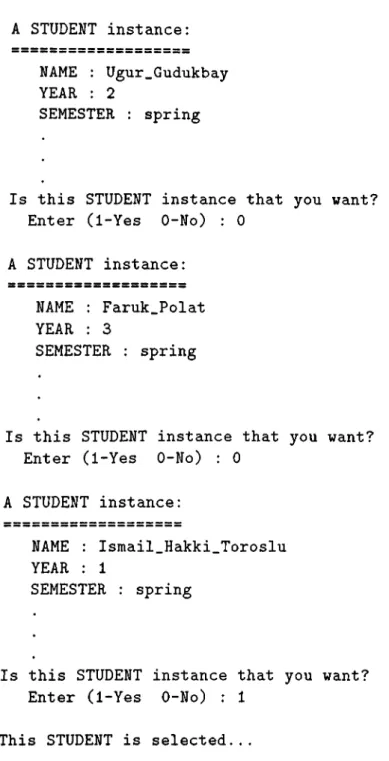
Variable NAME String and Primitive Enter a string: Ismail_Hakki_Toroslu
Variable YEAR Integer and Primitive Enter an integer: 1
Variable SEMESTER String and Primitive Enter a string: spring
Variable STANDING String and Primitive Enter a string: probation
Variable COURSES_TAKEN has Domain of Class COURSE and Collection A COURSE instance: CNO: mathlOl REQUIRED.YEAR: 1 REQUIRED.SEMESTER: fall GIVEN.SEMESTER: fall PREREQUISITES: TYPE: must_course
Is this COURSE instance that you want? Enter (1-Yes 0-No): 1
Figure 6.11: Creation of an instance of class “STUDENT.”
A COURSE instance: CNO: mathlOl REQUIRED_YEAR: 1 REQUIRED.SEMESTER: fall GIVEN.SEMESTER: fall PREREQUISITES: TYPE: must_course
Is this COURSE instance that you want to delete? Enter (1-Yes 0-No): 0
A COURSE instance: CNO: physlOl REQUIRED.YEAR: 1 REQUIRED.SEMESTER: fall GIVEN.SEMESTER: fall PREREQUISITES: TYPE: must.course
Is this COURSE instance that you want to delete? Enter (1-Yes 0-No): 0
A COURSE instance:
CNO: cslOl
REQUIRED.YEAR: 1
REQUIRED.SEMESTER: fall GIVEN.SEMESTER: fall spring PREREQUISITES:
TYPE: must.course
Is this COURSE instance that you want to delete? Enter (1-Yes 0-No): 1
Figure 6.12: Deletion of an in.stance of clciss “ COURSE.”