Design strategies for chemosensors and their applications in molecular scale logic gates
170
0
0
Tam metin
(2) I certify that I have read this thesis and that in my opinion it is fully adequate, in scope and in quality, as a thesis of the degree of Doctor of Philosophy.. …………………………………. Prof. Dr. Engin U. Akkaya (Principal Advisor). I certify that I have read this thesis and that in my opinion it is fully adequate, in scope and in quality, as a thesis of the degree of Doctor of Philosophy.. …………………………………. Prof. Dr. Özdemir Doğan. I certify that I have read this thesis and that in my opinion it is fully adequate, in scope and in quality, as a thesis of the degree of Doctor of Philosophy.. …………………………………. Assoc. Prof. Dr. Dönüş Tuncel.
(3) I certify that I have read this thesis and that in my opinion it is fully adequate, in scope and in quality, as a thesis of the degree of Doctor of Philosophy.. …………………………………. Assoc. Prof. Dr. Mehmet Bayındır. I certify that I have read this thesis and that in my opinion it is fully adequate, in scope and in quality, as a thesis of the degree of Doctor of Philosophy.. …………………………………. Assist. Prof. Dr. Serdar Atılgan. Approved for the Institute of Engineering and Sciences:. …………………………………. Prof. Dr. Levent Onural Director of the Graduate School.
(4) ABSTRACT DESIGN STRATEGIES FOR CHEMOSENSORS AND THEIR APPLICATIONS IN MOLECULAR SCALE LOGIC GATES Ruslan Guliyev PhD in Materials Science and Nanotechnology Supervisor: Prof. Dr. Engin Umut Akkaya January, 2013 Rational design and synthesis of novel (fluorescent) chemosensors is an active area of supramolecular chemistry. The recognition and signaling moieties are the most important parts in the design of these chemosensors. Despite the numerous studies that were reported in the literature, finding new strategies and mechanisms in the design of fluorescent probes is still of continuing interest. In this thesis, we have proposed some novel and desirable approaches for this purpose. Targeting of medically important anions, such as cyanide and fluoride (chapters 3 and 4), and developing a multianalyte chemosensor for cations (chapter 5) were successfully achieved through a rational design. Moreover, we realized that by the help of fluorescent chemosensors we can address some important solutions, at least to a certain point, to the troublesome issues that molecular logic concept faces. Recent research in molecular logic gates produced molecular equivalences of highly complex digital circuits. However, almost all the integration reported in the literature has been “virtual”, meaning that the output of a unimolecular system is adapted to the output of integrated set of logic gates, such that, the unimolecular system represents the equivalence of a certain complex digital design. Although this approach provides some important advantages, it does not truly solve the concatenation issue at the molecular level. Since physical concatenation of molecular logic gates is important for advanced molecular computing, some novel approaches should be introduced in order to overcome this problem. That is exactly what we are reporting in the chapter 6 of this thesis. Keywords: fluorescence, chemosensors, energy transfer, logic gates,concatenation. i.
(5) ÖZET KİMYASAL ALGILAYICILARIN TASARIMI VE BUNLARIN MOLEKÜLER MANTIK KAPILARINDAKİ UYGULAMALARI Ruslan Guliyev Malzeme Bilimi ve Nanoteknoloji, Doktora Tez Yöneticisi: Prof. Dr. Engin Umut Akkaya Ocak, 2013 Floresan moleküler algılayıcıların rasyonel tasarımı supramoleküler kimyanın aktif bir araştırma alanıdır. Tanıyıcı ve uyarıcı kısımlar bir moleküler algılayıcının en önemli parçalarıdır. Literatürde yayınlanan çok sayıda moleküler algılayıcının varlığına rağmen, yeni algılama mekanizmalarının bulunması ve literatüre katılması günümüzde halen yüksek öneme sahiptir. Bu amaca yönelik olarak da bu çalışmada bazı yeni ve umut vadeden yöntemler geliştirilmiştir. Tıbbi öneme sahip siyanür ve florür gibi anyonların tayini (Bölüm 3, 4) ve katyonlar için multi-analit algılayıcıların geliştirilmesi (Bölüm 5) rasyonel bir dizayn ile başarılı bir şekilde gerçekleştirildi. Ayrıca, floresan moleküler algılayıcıların yardımı ile moleküler mantık kapılarının karşılaştığı çok farklı problemlerin çözülebileceği tarafımızca farkedilmiştir. Moleküler mantık kapıları ile ilgili son zamanlarda yapılan araştırmalar, gelişmiş dijital devrelerin moleküler eş değerlerinin yapılabileceğini gösterdi. Moleküler seviyede bilgi işlem, moleküler mantık kapıları arasında entegrasyon gerektirir. Bu zamana kadar literatürde yer alan entegrasyonların neredeyse tamamı ‘sanal’ nitelik taşımaktadır. Bu, tek moleküler sistemin çıktısının bir dize entegre mantık kapısının çıktısına uyarlanması anlamına gelir. Özetle, bu moleküler sistem kompleks bir dijital devreyi temsil etmektedir. Bu yaklaşım önemli avantajlar sağlamasına rağmen, moleküler düzeyde entegrasyon problemini çözememektedir. İleri düzeyde bir moleküler bilgi işlemci tasarlamak için, şüphesiz ki moleküler mantık kapılarını fiziksel bir yolla birbirine bağlayacak metotlara ihtiyaç vardır. Bu çalışmada da tam olarak bu konu üzerine yoğunlaşılmıştır (Bölüm 6). Anahtar kelimeler: floresans, sensör, enerji transferi, mantık kapısı, entegrasyon. ii.
(6) ACKNOWLEDGEMENT. This dissertation describes the work effectuated at the Supramolecular Chemistry Laboratory at Material Science and Nanotechnology Institute (UNAM) of Bilkent University from September-2008 until December-2012. During this time, I had the pleasure of meeting and working with so many great people from whom I have learned a lot and who have had a deep influence on my life for the past years. With immense gratitude, I would like to express my foremost and sincere thanks to my research supervisor Prof. Engin Akkaya for giving me the opportunity to join his group and introducing me to this interesting field of research. In fact, I spent seven excellent years under his guidance and over the years, it has been an inspiration to witness his enthusiasm and vast scientific knowledge. His foresighted vision always improved the impact of our work by orders of magnitude. I feel proud for being a member of his 'SCL' group. Finally, I would also like to express my gratitude to him for always giving us the freedom to pursue our own ideas. I owe a special thank to Dr. Ali Coşkun, Dr. Özgür Altan Bozdemir, and Dr. Serdar Atılgan for their everlasting help and support, invaluable guidance as well as their unlimited knowledge and experience that I have benefited from greatly. I am sincerely grateful to my close friends Onur Büyükçakır, Yusuf Çakmak and his good wife Sündüs Çakmak, Tuğba Kütük and her husband İlker Kütük, Safacan Kölemen, and Bilal Kılıç for support, understanding and caring they provided through all these years. They have made my life different and because of them Ankara is going to be a significant and memorable place for me in the years to come. I also wish to express my warm and sincere thanks to 'teaching assistants trio' Tuğçe Durgut, Tuba Yaşar and Yiğit Altay for their necessary help, kind collaboration, joyful friendships and for always being there for me. Special thanks are also extending to my friend Bora Bilgiç for the graphical designs and cover pictures he provided for our manuscripts.. iii.
(7) All the present and past members of Akkaya Lab - thank you all so much for your valuable friendships, wonderful collaborations, and for the memorable experiences we had together during the past years. Dr. Fazlı Sözmen, Dr. Esra Tanrıverdi, Dr. Murat Işık, Dr. Deniz Yılmaz, Dr. Gökhan Barın, Ahmet Atılgan, Bilal Uyar, Ziya Köstereli, Ahmet Bekdemir, Nisa Yeşilgül, İlke Şimşek, Hatice Turgut, Muhammed Büyüktemiz, Gülcihan Gülseren, Tuğrul Nalbantoğlu, Merve Kaplan, Elif Ertem, Hande Boyacı Sencer Selçuk, Dr. Seda Demirel and others. It has been a great pleasure for me to work with you guys. I also would like to thank all members of UNAM family for providing a multidisciplinary research atmosphere and for joyful friendships. I gratefully acknowledge the scholarship fund program for foreign students, which was run by the TÜBİTAK to provide support for foreign students pursuing their PhD studies in Turkey. I am grateful for the privilege of meeting Şeyma Öztürk who has significantly important contributions on the work presented in this dissertation. Other than being an outstanding collaborator, she is a kind lab partner and a good friend. This thesis is dedicated to my family - my father, mother, sister and brother and to my uncle Şahid. There is no way to thank them for their love and care and endless support, trust and encouragement they have provided all these years for me.. iv.
(8) LIST OF ABBREVIATIONS. AcOH. : Acetic Acid. Bodipy. : Boradiazaindacene. CHCl3. : Chloroform. DDQ. : Dichlorodicyanoquinone. DMF. : Dimethylformamide. ET. : Energy Transfer. Et3N. : Triethylamine. FRET. : Förster Resonance Energy Transfer. HOMO. : Highest Occupied Molecular Orbital. ICT. : Internal Charge Transfer. IFE. : Inner Filter Effect. LUMO. : Lowest Unoccupied Molecular Orbital. MALDI. : Matrix-Assisted Laser Desorption/Ionization. MS. : Mass Spectroscopy. NMR. : Nuclear Magnetic Resonance. PET. : Photoinduced Electron Transfer. TFA. : Trifluoroacetic Acid. THF. : Tetrahydrofuran. TLC. : Thin Layer Chromotography. TOF. : Time of Flight. v.
(9) TABLE OF CONTENTS. CHAPTERS 1. Introduction......................................................................................................... 2 2. Background ......................................................................................................... 8 2.1.. Photoluminescence ........................................................................................ 8. 2.1.1.. Absorption of Light and Electronically-Excited States ......................... 9. 2.1.2.. The Physical Deactivation of Excited States ....................................... 12. 2.2.. Fluorescent Dyes ......................................................................................... 15. 2.3.. Molecular Sensors ....................................................................................... 17. 2.4.. Fluorescent Chemosensors .......................................................................... 19. 2.4.1.. Photoinduced Electron Transfer (PET) ................................................ 21. 2.4.2.. Intramolecular charge transfer (ICT) ................................................... 26. 2.4.3.. Energy Transfer (ET) ........................................................................... 29. 2.5.. Cation Recognition ...................................................................................... 35. 2.6.. Anion Recognition ...................................................................................... 39. 2.7.. Bodipy Dyes ................................................................................................ 44. 2.7.1.. Routes to Bodipy Synthesis ................................................................. 46. 2.8.. Logic Gates: Fundamental Building Blocks of Digital Systems ................. 48. 2.9.. Molecular Logic Gates: An Alternative Perspective ................................... 50. 2.10.. Higher Functions with Molecular Logic .................................................. 53. 2.10.1.. Half Adder and Half Subtractor ....................................................... 54. 2.10.2.. Full-Adder and Full-Subtractor ........................................................ 56. 2.10.3.. Other Higher Functions .................................................................... 59. 2.11.. Molecular Logic: Quo Vadis ?................................................................. 61. vi.
(10) 3. Cyanide Sensing via Metal Ion Removal ........................................................ 62 3.1.. Objective ..................................................................................................... 63. 3.2.. Introduction ................................................................................................. 63. 3.3.. Results and Discussions .............................................................................. 64. 3.4.. Experimental Details ................................................................................... 69. 3.4.1.. UV-vis and Fluorescence Titration Experiments ................................. 69. 3.4.2.. Synthesis .............................................................................................. 70. 4. Expanded Bodipy Dyes: Anion Sensing.......................................................... 72 4.1.. Objective ..................................................................................................... 73. 4.2.. Introduction ................................................................................................. 73. 4.3.. Results and Discussions .............................................................................. 74. 4.4.. Experimental Details ................................................................................... 87. 4.4.1. 4.5.. Synthesis .............................................................................................. 88. Conclusion ................................................................................................... 89. 5. Selective Manipulation of ICT and PET Processes ....................................... 90 5.1.. Objective ..................................................................................................... 91. 5.2.. Introduction ................................................................................................. 91. 5.3.. Synthesis ...................................................................................................... 94. 5.4.. Results and Discussions .............................................................................. 97. 5.5.. Experimental Details ................................................................................. 109. 5.5.1.. UV-Vis Titration Experiments ........................................................... 110. 5.5.2.. Reaction Procedures ........................................................................... 110. 5.6.. Conclusion ................................................................................................. 117. 6. From Virtual to Physical : Integration of Chemical Logic Gates .............. 118 6.1.. Objective ................................................................................................... 119. vii.
(11) 6.2.. Introduction ............................................................................................... 119. 6.3.. Results and Discussions ............................................................................ 121. 6.4.. Experimental Details ................................................................................. 133. 6.5.. Conclusion ................................................................................................. 140. 7. EPILOGUE ..................................................................................................... 142 8. BIBLIOGRAPHY ........................................................................................... 145. viii.
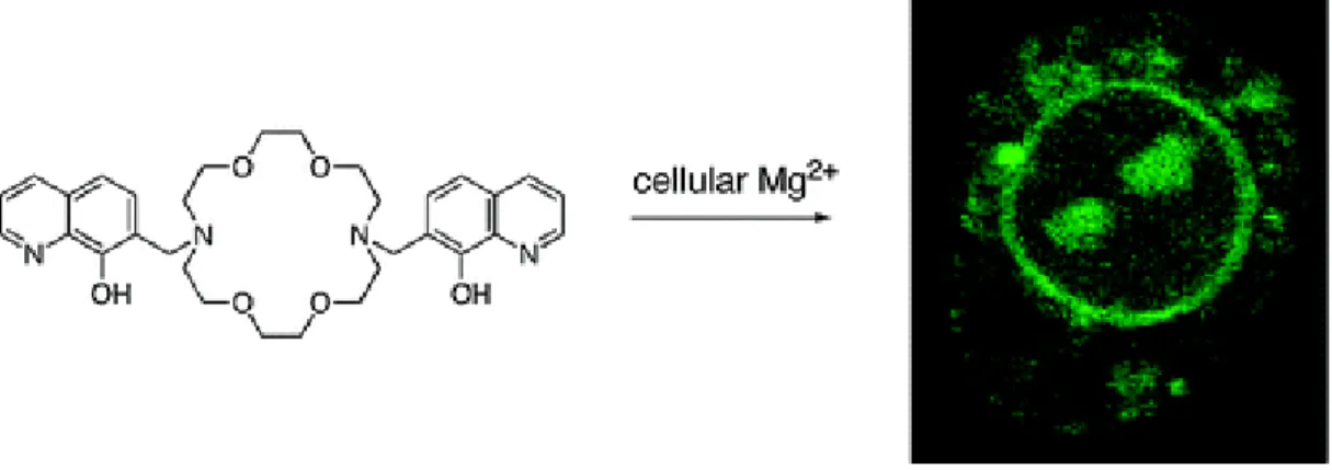
(12) LIST OF FIGURES. Figure 1. K+ probe proposed by Trend et al. ............................................................... 2 Figure 2. Comparison between molecular and supramolecular chemistry ................. 3 Figure 3. Possible de-excitation pathways of excited molecules ................................ 8 Figure 4. Morse potential diagram ............................................................................ 11 Figure 5. The Perrin-Jablonski diagram .................................................................... 13 Figure 6. Stokes' shift ................................................................................................ 14 Figure 7. Distribution of dye families in the visible region ...................................... 16 Figure 8. Molecular structure of Saxitoxin and probe compound 1.......................... 19 Figure 9. Schematic representations for the types of fluoroionophores .................... 20 Figure 10. PET mechanism ....................................................................................... 21 Figure 11. Some examples of PET based fluorescent chemosensors ....................... 23 Figure 12. Oxidative PET mechanism ...................................................................... 23 Figure 13. Coordination of zinc triggers the oxidative PET mechanism .................. 24 Figure 14. Reverse PeT (d-PeT) mechanism ............................................................ 25 Figure 15. Spectral displacements of PCT type sensors ........................................... 26 Figure 16. Crown containing PCT sensors ............................................................... 27 Figure 17. Bidirectional switching of the dyes related to ICT .................................. 28 Figure 18. Förster type (through space) and Dexter type (through bond) ET........... 29 Figure 19. Schematic representation of the FRET process ....................................... 30 Figure 20. A Bodipy based Förster type energy transfer system .............................. 32 Figure 21. Through-bond energy transfer cassettes .................................................. 33 Figure 22. Ligand-metal based Dexter type energy transfer system ......................... 34 Figure 23. Hg2+ selective chemosensors ................................................................... 36 Figure 24. Sodium selective fluoroionophore ........................................................... 37 Figure 25. 8-Hydroxyquinoline derivatives for sensing magnesium ion65 ............... 38 Figure 26. Selective fluorescent chemosensors for Zn(II) ions ................................ 39 Figure 27. Displacement assay for citrate anion ....................................................... 41 Figure 28. Chemosensors for ATP ............................................................................ 42 Figure 29. Fluorogenic and Chromogenic sensors for fluoride anion....................... 43. ix.
(13) Figure 30. First synthesis of boron-dipyrrin dye ....................................................... 44 Figure 31. Structures and numbering of dipyrromethane, dipyrrin and Bodipy ....... 45 Figure 32. Tautomers of phenyl-Bodipy that affect the fluorescence ....................... 45 Figure 33. Acid catalyzed condensation of aromatic aldehydes with pyrroles ......... 46 Figure 34. Proposed mechanism for the formation of dipyrrin ................................. 47 Figure 35. Truth tables and schematically representations for common logic gates 49 Figure 36. Two-input molecular AND-logic gate by de Silva et. al. ........................ 51 Figure 37. XOR & XNOR gate designed by de Silva et al. ...................................... 52 Figure 38. Half-adder logic diagram along with its truth table ................................. 54 Figure 39. First molecular half adder (XOR and AND gates) .................................. 55 Figure 40. Logic representation and truth table of half-subtractor ........................... 55 Figure 41. The first molecular half subtractor based on tetraphenylporphyrin117..... 56 Figure 42. Absorption spectra for different forms of fluorescein122 ......................... 57 Figure 43. A full adder based on fluorescein molecule............................................. 58 Figure 44. A full subtractor based on fluorescein molecule ..................................... 59 Figure 45. General representation for sequential logic circuit .................................. 60 Figure 46. Synthesis of chemosensor 28 ................................................................... 64 Figure 47. Absorbance (a) and emission (b) spectra of compound 28 ...................... 65 Figure 48. Absorbance (a) and emission (b) spectra of compound 28+Cu(II) ......... 66 Figure 49. Emission spectra of compound 28+Cu(II) ............................................... 67 Figure 50. Emission ratios for the compound 28+Cu(II) .......................................... 68 Figure 51. Synthesis of the target compound 29 ....................................................... 74 Figure 52. Ortep drawing of the compound 29 ......................................................... 75 Figure 53. 11B NMR spectra of the reference (30) and the target compound (29).... 76 Figure 54. 19F NMR spectrum of compound 29 and reference Bodipy .................... 77 Figure 55. 19F NMR spectrum of Boron trifluoride diethyl etherate ........................ 78 Figure 56. Absorbance spectra of target compound 29 (10.0 µM) in chloroform .... 79 Figure 57. Titration of 29+F- (10.0 µM) with the increasing fluoride (TBA salt) .... 80 Figure 58. 11B NMR spectra of the reference (30) and the target compound (29).... 81 Figure 59. 11B NMR spectrum of Tetrabutyl ammonium Tetrafluoroborate salt..... 81 Figure 60. 11B NMR spectra of 29 ............................................................................ 82 Figure 61. 11B NMR spectra of the target compound (29) after the.......................... 83. x.
(14) Figure 62. 11B NMR spectra of 29 after the addition of............................................ 84 Figure 63. (a) MS (TOF - ESI) of compound 29 ...................................................... 85 Figure 64. (a) MS (TOF - ESI) of compound 29 ...................................................... 86 Figure 65. Target structures for two-input AND logic 32, Half-Adder 34 ............... 94 Figure 66. Synthesis of target compound 32 ............................................................. 95 Figure 67. Synthesis of target compound 34 ............................................................. 95 Figure 68. Synthesis of target compound 37 ............................................................. 96 Figure 69. Emission spectra of 32 (1.67 μM) in acetonitrile..................................... 97 Figure 70. Schematic representation of the frontier orbitals ..................................... 98 Figure 71. Qualitative assessment of relative energy levels of frontier .................. 100 Figure 72. Absorbance spectra of compound 34 in acetonitrile.............................. 100 Figure 73. Absorption spectra of compound 34 (3.2 μM) in acetonitrile................ 101 Figure 74. Emission spectra of compound 35 (1.67 µM) in acetonitrile ................ 102 Figure 75. Leftside is the emission specta of compound 35 (1.67 µM) .................. 102 Figure 76. Absorption specta of compound 37 (2.0 µM) in acetonitrile................. 103 Figure 77. Emission spectra of 37 (2.0 μM) in acetonitrile..................................... 104 Figure 78. ITC titration curves of compound 34 in acetonitrile.............................. 107 Figure 79. ITC titration curves of reference compound 31 in acetonitrile .............. 107 Figure 80. ITC titration curves of compound 32 in acetonitrile ............................. 108 Figure 81. Reversible photochemical conversion of thionine into leuco form ....... 121 Figure 82. Transmission and absorption spectra of thionine .................................. 122 Figure 83. Schematic representation of first independent AND gate ..................... 123 Figure 84. . Schematic representation of second independent AND gate ............... 123 Figure 85. Synthesis of logic gate modules ............................................................ 124 Figure 86. A representation of the operation of the coupled AND logic gates ....... 124 Figure 87. Operation of the integrated logic gates (IFE). ....................................... 125 Figure 88. Reversibility of the thionine photochromic response ............................ 126 Figure 89. The “clicked” molecule 45 .................................................................... 128 Figure 90. Absorbance and emission spectra of compound 42 (2 µM) ................. 128 Figure 91. Absorbance spectra of Compound 45 (3.0 µM) in acetonitrile ............. 129 Figure 92. Operation of the integrated logic gates. ................................................. 130 Figure 93. Effect of PET on compound 45 ............................................................. 130. xi.
(15) Figure 94. Less effective ET because of the inadequate spectral overlap............... 131 Figure 95. Output is high (1) when all the inputs exist at the same time ................ 131 Figure 96. A representation of the two coupled AND logic gates via click chemistry .................................................................................................................................. 133. xii.
(16) LIST OF TABLES. Table 1. Impact of the electromagnetic radiations on molecular structures ................ 9 Table 2. Truth tables for full-adder and full-subtractor............................................. 57 Table 3. Energy levels obtained for dye 32 and various metal complexes ............... 99 Table 4. Spectroscopic data for compounds 32, 34, 35, 37 ..................................... 105 Table 5. Binding constants determined by isothermal titration calorimetry ........... 106 Table 6. Quantum yields for all compounds ........................................................... 132. xiii.
(17) CHAPTER 1. INTRODUCTION. 1.
(18) 1.. INTRODUCTION. Think about a patient lying on the operating table and undergoing a specific surgery. Any mistaken or mismeasured diagnostic data before or during the operation may mislead the surgeon that could result in the unfortunate end of his or her life. That is why, measuring physiologic values are highly important, and those medical diagnosis are carried out with great care. There are wide range of parameters, such as blood dioxygen levels, glucose etc., to be monitored prior or during the specific operations. However, sometimes it is a really difficult task to determine the concentration of some important ions among the other competitive species present in bodily fluids of a patient. It is obvious that, for this kind of situations, better analytical devices or testing methods should be developed. For example, during the cardiovascular bypass surgical procedures, continuous monitoring of blood K+ ion levels is very important. Considering the presence of excess Na+ ions (mM levels) in the same matrix, developing a detection method for K+ ions was challenging. Due to this reason, there wasn't a good detection method for monitoring the blood K+, until recent past. Trend et al. 1 addressed a solution to this clinical issue by putting forward the molecule below (Figure 1).. Figure 1. K+ probe proposed by Trend et al. Their proposed probe was a cryptand moiety tethered to a coumarin fluorophore which emits fluorescence upon binding of K+ ions. The intensity of emitted light is proportional to the K+ concentrations. Since, even excess amount of Na+ ions (145 mM) didn't cause any change in the fluorescence property, the selectivity for K+ ions was successfully achieved.. 2.
(19) Moreover, by incorporating that molecule to a polymeric backbone, they succeeded in constructing a flow-through device, that is capable of continuously and quantitatively monitoring the blood K+ levels. It is exactly that device, which provides an excellent example of 'supramolecular chemistry' being used for the benefits of an ordinary man in the street. In 1987, the Nobel Prize for chemistry was awarded to triad of scientists - Donald J. Cram, Charles J. Pedersen, and Jean-Marie Lehn in recognition of their brilliant work in the field of Supramolecular Chemistry. That day, this field has proved to be a well established branch of modern chemistry. Since it lays on the crossroads between chemistry, biochemistry, physics and technology, it is highly interdisciplinary field, and has developed very rapidly in the last three decades. 2,3 Since the field is expanding as it advances, numerous definitions describing it were reported in the literature. Phrases like 'chemistry beyond the molecule', ' the chemistry of the noncovalent bond', or ' non-molecular chemistry' are some of them, to name a few. The modern concept of supramolecular chemistry was introduced by Jean-Marie Lehn, which he defined as the ‘‘chemistry of molecular assemblies and of the intermolecular bond’’. 4 From these descriptions, it can be easily inferred that, contrary to the traditional chemistry, supramolecular chemistry focuses on the weaker and reversible noncovalent interactions between molecular species. These interactions could be in the form of hydrogen bonding, metal coordination, hydrophobic forces, Van der Waals forces, π-π interactions and electrostatic forces.. Figure 2. Comparison between molecular and supramolecular chemistry. 3.
(20) During the early days of this field, supramolecules mainly comprised two components, a host and a guest species (Figure 2), which interact with one another in a noncovalent manner. However, dramatic developments have occurred since then, such that past decade has seen its expansion into some interesting areas of materials chemistry and nanoscience with various potential and real applications. A wide range of chromophores, fluorophores, and redox-active chemical species have been successfully incorporated into supramolecular frameworks. Utilizing the rich host-guest chemistry, they become ideal candidates for sensing applications. Moreover, contributions of supramolecular methods in the design and manufacture of molecular scale functional devices are significantly important. Developing molecular scale logic devices, designing and synthesizing artificial biological agents, and developing new therapeutic agents, are some of the very hot and novel application areas of this field. No doubt that, as human needs are increasing, supramolecular chemistry concepts are going to be more involved in our daily life to facilitate it. The research studies that constitute this thesis provide some novel and inspiring examples for molecular recognition in host-guest complexes, which is the oldest and generic process in supramolecular chemistry. Additionally, herein, implementation of those recognition mechanisms in the development of functional molecular logic devices was also reported. Design and synthesis of novel (fluorescent) chemosensors constitutes the main part of this thesis. The recognition and signaling moieties are the most important parts in the design of a chemosensor. Development of receptors sensitive to specific analyte, and improvement of dye molecules (signaling part) in order to get more applicable probes are the two main research areas within this context. Rational design of a better chemosensor, targeting a specific analyte, still remains as a challenge for the researchers working on this field. And it is an undeniable fact that, in order to be more realistic, suggested sensing probes should be applicable in biological media. Thus, water solubility becomes as one of the important barriers to be overcome. It has to be noted that, the sensing of analytes in aqueous solutions. 4.
(21) requires strong affinity for analytes (because of their strong hydration effects) in water as well as the ability to convert analyte recognition into a fluorometric and/or colorimetric signals. So it is much more challenging to selectively recognize analytes in aqueous systems compared to organic ones. It can be concluded that, design of a sensory probe requires at least the followings: recognition between analyte and binding site should be well identified, depending on the nature of the analyte water solubility should be provided, and most importantly, selectivity of the target analyte over other concomitants should be considered. This topic is covered briefly within the second chapter of this thesis (2.3, 2.4, 2.5, 2.6). These types of chemosensors have attracted much interest during the last two decades. Despite the numerous studies that were reported and reviewed extensively in the literature, finding new strategies and mechanisms in the design of fluorescent chemosensors is still of continuing interest. Studies presented in the chapters 3 and 4 of this thesis, briefly summarizes our recent contributions to this field. On the other hand, by using the accumulated knowledge of chemosensor design, we are investigating their applications to different fields of supramolecular chemistry. We realized that ‘colorful’ organic molecules are very promising in the mimicking of macroscopic digital processing devices. In fact it was Professor A. Prasanna de Silva, who has reported this analogy for the first time. Contrary to the idea behind, the molecule operating as an ‘AND’ gate was very naive from synthetic perspective. Uniqueness of that study is based on the (emitted) light which is used as an output signal. It is really difficult to detect any change that happens at the molecular level. However, if the change occurs in the optical character of the molecules, then it becomes easier to detect it with high sensitivity. Molecular logic gates, based especially on fluorescence phenomenon have been widely preferred so far, due to the distinct advantages of fluorescence detection in terms of sensitivity and selectivity. Therefore, colored molecules especially fluorescent ones have become very important tools in the design and construction of molecular scale logic gates. More detailed information regarding to this topic can be found in the 'background' chapter (2.8, 2.9, 2.10, and 2.11).. 5.
(22) Various logic gates based on organic molecules have been built due to the research work dedicated to the development of these systems so far but, molecular logic gates are still far from achieving practical applications in computing. While functional integration is possible within single molecule, at least partly because of input-output heterogeneity, integration of logic gates to implement more complex functions is far from being straight-forward. That’s primarily because of the problem in the physical integration of molecules since contrary to the electronic devices we use no wiring. To solve this issue, new methodologies should be developed in terms of intermolecular communication, such that the problem of gate to gate communication is diminished. Our works along these lines are presented in chapters 5 and 6.. 6.
(23) CHAPTER 2. BACKGROUND INFORMATION. 7.
(24) 2.. BACKGROUND. 2.1. Photoluminescence Most elementary particles are in their ground state at room temperature. When these particles are exposed to an electromagnetic irradiation, depending on the nature of the substance, absorption of a photon with proper energy may take place. This process leads to a rapid formation of an electronically excited state which is followed by dissipation of the excess energy in different forms (Figure 3). The term 'Photoluminescence' can be defined as an optical property of a substance which absorbs photon upon irradiation and release them radiatively. 5 Depending on the nature of the excited state, the emission of light can be divided into two categories as fluorescence and phosphorescence. Details related to the photoluminescence process will be discussed in the following subsections.. Figure 3. Possible de-excitation pathways of excited molecules. 8.
(25) 2.1.1. Absorption of Light and Electronically-Excited States Once a molecule is irradiated by photons with proper energy, absorption of photons and transition of an electron from outer molecular orbitals (HOMO, HOMO-1 etc.) to unoccupied orbitals (LUMO, LUMO+1 etc.) of the molecule will happen very rapidly. In most cases, a photon of light of wavelength lying in the UV- Visible region of the electromagnetic spectrum is sufficient in energy for such electronic transitions. Due to this reason, the region of the spectrum covering 200- 800 nm range is sometimes named as the 'photochemical window'. 6 Moreover, other regions of the electromagnetic spectrum may induce interesting changes on the molecule upon irradiation. They are roughly summarized in the table below. Radiation. Wavelength. Photon Energy. Results of Absorption. Gamma rays. l<0.01 nm. >1 MeV. Nuclear reactions. X rays. 0.01-10 nm. 124 eV-120 keV. Transitions of inner atomic electrons. UV. 10-400 nm. 3.1-124 eV. Transitions of outer atomic electrons. Visible. 400-750 nm. 1.7-3.1 eV. Transitions of outer atomic electrons. Infrared. 750nm-15 µm. 80meV-1.7 eV. Molecular vibrations. Far IR. 15µm-1 mm. 1.2meV-80meV. Molecular rotations. Radar. 1mm-1 m. 1.2µeV-1.2meV. Oscillation of mobile electrons. Table 1. Impact of the electromagnetic radiations on molecular structures The absorption spectrum of a sample can be measured by UV-Vis absorption spectroscopy and at a specified wavelength the intensity of the absorption depends on the molar absorption coefficient, ε, of the molecule. It is the probability of an electronic transition at a given wavelength. In other words, its value gives us the information of how 'allowed' a transition is. 'Allowed' and 'forbidden' terms are beyond the classical physics, as they represent the results of quantum mechanical calculations. Since detailed quantum chemical integrations (equations) are out of the scope of this thesis, a qualitative overview will be presented within the upcoming paragraphs.. 9.
(26) As it is stated before, the value of ε indicates the probability of an electronic transition from ground state to excited state of a molecule. There is a set of rules (a.k.a. selection rules) that constrain the possible transitions, and they are based mainly on two components which are spin and symmetry. Spin component displays kind of a solid property such that an electronic excitation is allowed if and only if the total spin remains unchanged during the transition. In other words, if a transition involves a spin change (e.g. singlet to triplet), then that transition is said to be forbidden. On the other hand, the symmetry component is related to the symmetry of the ground and excited states which determine the transitions to be allowed or forbidden. However, by just considering the symmetry term it is difficult to conclude that the transition is going to be forbidden. The symmetry calculations are done for the molecules in idealized conditions, but for a real molecule the symmetry may be distorted by the presence of some environmental effects like solvent or a heavy atom on the molecule. Keeping all these in mind and by analyzing the ε value we can comment on a transition in terms of how allowed or forbidden it is. The transition is said to be 'fully allowed' if ε is measured to be greater than 105 M-1 cm-1. If it is smaller than 100 M-1 cm-1, then the transition is 'forbidden', meaning that the molecule does not absorb well at this wavelength. The third option is the ε value lying in between 102- 104 M-1 cm-1. In this case the transitions are said to be 'partially allowed' and this condition is coming from the symmetry component. Therefore, if a transition is spin forbidden and symmetry allowed, then the probability of it is very low (ε<100). On the other hand, if it is spin allowed but symmetry forbidden, then moderate absorption is observed and ε value is going to be between 102-104 M-1 cm-1. Another important consequence regarding the light absorption topic is the shape of spectra which is related to the ε value at each wavelength. It is a well known fact that, during the light absorption that leads to an electronic transition, number of changes in both electronic and vibrational states occurs. For an individual electronic transition, the probability of a transition between vibrational levels of each orbital (e.g. HOMO and LUMO) may be higher or lower than the others due to the overlap amount of the two vibrational wave functions. For example, when the lower and upper electronic states have similar internuclear separations, there will be greater. 10.
(27) overlap between wave functions of vibronic states, resulting in the more intense transitions between the vibrational levels of the electronic states. Franck-Condon Principle governs all these transition, which simply states that: since the transition from one electronic state to another takes place very rapidly, nuclei of the vibrating molecule can be assumed to be fixed during the electronic transition. In other words, nuclei move much more slower than the lighter electrons, so the nuclear geometry would remain very much the same (in terms of position and velocity) as it was before the electronic transition. As a consequence of this principle, an electronic transition is represented by a vertical arrow (Figure 4), indicating the electronic transitions within stationary nuclei. 7. Figure 4. Morse potential diagram A hypothetical Morse potential diagram of the ground and excited states and probable absorption and fluorescence spectra are depicted in figure 4. By looking at the diagram (left side) it can be claimed that the internuclear distance has remained unchanged during the transition. However, there is a little shift between the nuclear coordinates of ground and excited states of the molecule which is represented as r01. The diagram also shows that there are many vibronic transitions that are allowed.. 11.
(28) However, by qualitative analysis we can say that some of them are more probable than others, meaning that the intensities of vibronic transitions will be different. The most probable transition between the vibrational level in HOMO and those in LUMO will be the one where the wavefunctions overlap the most along the vertical arrow. In our case the best overlap is between ν=0 in the ground state and ν=2 in the excited state. Thus in the absorption spectrum, this transition is observed as the most intense absorption band. Due to the very large number of vibrational levels and interactions between themselves and solvent molecules, generally organic molecules do not display those fine structures in solution and solid phases. Rather, they appear as broad curves, like a line drawn over the peak maxima of the individual transition peaks. In addition, the Franck-Condon Principle is equally applicable to both absorption and fluorescence phenomena. The red arrow in the diagrams (Figure 4) represents the decay to the ground state via photon emission. Details of this and other types of relaxation processes will be covered in the next section.. 2.1.2. The Physical Deactivation of Excited States When photons with significant energy are incident on molecules, an electron in the molecule can be promoted to higher-energy molecular orbitals. These types of excitations are typical for the visible and/or ultraviolet range photon energies, producing electronically excited states. These excited states are energetically unstable thus, immediately lose their excess energy through a variety of deactivation processes. The Perrin-Jablonski diagram is convenient for visualizing in a simple way the most typical processes that may happen after photon absorption (Figure 5). Jablonski diagram illustrates the properties of excited states as well as their relaxation processes. Following the light absorption, the vibrational levels of some upper excited states will be populated with electron density. These electrons immediately relax to the lowest vibrational level of S1 by vibrational relaxations within picosecond or less, and this process is called as the internal conversion. All the other photochemical processes (fluorescence, quenching etc.) are more likely to. 12.
(29) happen from the lowest vibrational state of S1. Actually, this is the basis of Kasha's rule 8, which states that considering an excited molecule all the photochemical reactions and luminescence emission will always originate from the ν=0 of S1, since the relaxation rate to the lowest vibrational level of S1 is the fastest deactivation process. Depending on the nature of the excited molecule, the excited electron at S1 now may undergo either fluorescence by emitting photons, or intersystem crossing to the triplet state or it may just relax to the S0 via releasing the excess energy by internal conversion, as explained above.. Figure 5. The Perrin-Jablonski diagram Intersystem crossing to the triplet state T1 is a forbidden transition in the idealized conditions, and will only happen if the electron in the S1 state may undergo a spin conversion. There are few conditions that make such transitions favorable, such as presence of a heavy atom and/or exciton coupling within a molecule. Relaxation from T1 is a radiative process and termed as the phosphorescence. As expected, it is a lower-energetic radiation, and because of the multiplicity of its state (T1), the rate of. 13.
(30) the radiative decay to the singlet S0 state is much more slower compared to fluorescence. Details including timescales of these processes are depicted in the figure 5, shown above. Fluorescence is a spin-allowed radiative relaxation due to the same multiplicity of the excited (S1) and the ground states (S0). Therefore, it occurs on relatively short timescales, presumably, within the range of picoseconds to microseconds. As can be seen in the Jablonski diagram, emitted light always has a longer wavelength (less energetic) than the absorbed light due to limited energy loss by the molecule prior to emission. The difference (usually in frequency units) between the spectral positions of band maxima of the absorption and luminescence is called Stokes’ shift (Figure 6). 9 The main cause of Stokes’ shift is the rapid non-radiative decay to the lowest vibrational level of S1. In addition to this effect, fluorescent molecules can display further Stokes’ shift due to solvent effects, excited-state reactions, complex formation and energy transfer. 10. Figure 6. Stokes' shift For a fluorescent molecule, the fluorescence quantum yield Φ and the lifetime τ are two essential photophysical parameters. The former is the ratio of the number of photons emitted by S1 to the number of photons absorbed by S0, which can be 14.
(31) determined by the below equation where kf and knr are the rates of radiative and nonradiative transitions, respectively. The higher the quantum yield, the higher the fluorescence intensity is. Moreover, the fluorescence quantum yield of a molecule may also be determined by comparing the area under its fluorescence spectrum with that of a reference compound whose quantum yield is known. 11 Φ = kf / kf+ knr The average time the molecule remains in its excite state is called the average lifetime of the excited states < τ > and it is numerically equivalent to the fluorescence lifetime which is determined by the time-resolved measurements. Fluorescence lifetime is a kinetic parameter which is inversely proportional to the sum of the rate constants and is represented by the equation below. 12 τ = 1 / kf+ knr. 2.2. Fluorescent Dyes A common feature of almost all traditional dyes is that they absorb particular wavelengths of visible light, leaving the remaining wavelengths to be reflected and seen as color by the observer. For example, a traditional yellow dye absorbs violet light and thus appears yellow. The energy coming from the absorbed light is stored in the electron structure of the dye molecule and given off in the form of heat. The unique feature of a fluorescent dye is that they not only absorb light in the traditional sense, but this resulting energy is then dissipated in the form of emission of light. Organic dyes that emit ultraviolet (UV), visible (Vis), and near infrared (IR) regions are of great interest, and have wide application fields. Especially, the advantage of low price, safety and accuracy make them very promising, considering the applications in biotechnology and medical diagnostics. 13,14 The most common dyes whose emissions span the UV to IR spectrum are shown in Figure 7 (next page).. 15.
(32) Figure 7. Distribution of dye families in the visible region In the above figure, absorbance and emission maxima along with spectral regions covered by a particular dye family are highlighted. Tetramethyl rhodamine (TMR), carboxytetramethyl rhodamine (TAMRA), and carboxy-X-rhodamine (ROX) are all rhodamine based dyes. The UV dyes are typically pyrene, naphthalene, coumarin based structures, while the visible and near IR dyes include fluorescein, rhodamine, bodipy, and cyanine based derivatives (Figure 7). These dyes differ from each other in many aspects such as their structures, spectroscopic properties and chemical reactivities. Diversity of photochemical properties makes it easy to select a specific dye for a particular purpose. 15 Moreover, having rich chemistry (in terms of chemical modifications) is another important property of a fluorescent dye, which should be considered carefully prior to choosing it for a specific application. Members of some dye families, such as cyanines (Cy), are closely related in structures, whereas others, such as the AlexaFluor compounds, are quite diverse. All dye families have both advantages and disadvantages depending on the intended 16.
(33) application. For example, fluorescein which is one of the most common used fluorophore in bio-labeling 16 is popular because of its high quantum yield, relatively high molar extinction coefficient, good water solubility, and ease of bioconjugation. On the other hand, it has a high rate of photobleaching 17, is pH sensitive 18, and can self-quench at high degrees of substitution.19 Another important family of dyes are BODIPY based ones and will be discussed in detailed in the separate section (2.7). As stated above, it is the emitted light that makes fluorescent dyes (fluorophores) unique when compared to traditional absorbing molecules. Depending on the substituents on it, emission intensity of a fluorophore may vary. This gives us the opportunity to design the fluorophore rationally and control the emission intensity efficiently. On-off type fluorescence control, in which the increase or decrease of fluorescence intensity at a single emission wavelength is observed, is the most frequently encountered example. This and other types of modulation mechanisms are the heart of fluorescent chemosensor design and will be covered briefly just after discussing the 'molecular sensor' phenomena.. 2.3. Molecular Sensors A molecular sensor or a chemosensor is a molecule that can report the presence of an analyte by some physical means. A sensor should ideally be selective for a particular guest molecule and it should allow the observer to monitor that analyte's concentration as well as reporting the presence of it. This is important for medical diagnostics and monitoring environmental pollution. 20 There are numerous analytical methods that are available for the detection of various analytes, however they are expensive and often require samples of large amount. Thus, the molecular sensors gain primary importance in this area. Molecular sensors can be split into two major categories; these are electrochemical sensors and optical sensors. Electrochemical sensors can be obtained with the attachment of a redox active unit to the receptor moiety. A change in the redox properties of the receptor can be detected by an electrochemical technique such as cyclic voltametry (CV). 17.
(34) Optical sensors, on the other hand, constitute light based investigation methods. The most common type of it is fluorescent chemosensors which carry information regarding the analyte on the emitted light. Other methods follow the response via the changes measured in the absorbance of a sample and can be referred to as the colorimetric sensors. High sensitivity, high speed, and safety parameters make the fluorescence detection very advantageous over other optical methods. The principal advantage of a fluorescent chemosensor over a colorimetric sensor is its high sensibility. This is so because the emitted fluorescence signal is proportional to the analyte. concentration. whereas. in. absorbance. measurements,. the. analyte. concentration is proportional to the absorbance, which is related to the ratio between intensities measured before and after the beam passes through the sample. Thus, in fluorescence, an increase of the intensity of the incident beam results in a larger fluorescence signal whereas this is not so for absorbance. In other words, while fluorescent techniques can measure analyte concentrations at picomolar levels, absorbance measurements can detect concentrations only as low as micromolar scale. As a result, using fluorescence, one can monitor very rapid changes in concentrations even at very low ranges. They are, therefore, very sensitive and suitable for use in biological systems. The point of safety refers to the fact that samples are not affected or damaged during the measurements, and no hazardous by products are generated. A recent example is provided by a sensor for saxitoxin developed in the Gawley research group shown in figure 8. 21 They reported an azabodipy derivative (1) containing either 18- or 27-membered crown ether rings as a synthetic sensor which is evaluated in the detection of paralytic shellfish toxin saxitoxin. According to the design, compound 1 is nonfluorescent molecule and upon complexation with the toxin its fluorescence property changes considerably, that is, a 3-fold enhancement is observed on the fluorescence spectrum. This is the way how they obtained a sensory response for the mentioned analyte. They also got some interesting results while comparing the crown ether sizes on the molecule in terms of binding constants. This and more detailed results are briefly speculated within the cited article.. 18.
(35) Figure 8. Molecular structure of Saxitoxin and probe compound 1 Fluorescent chemosensors have become an important research field during the past two decades. Despite the many number of studies that were reviewed extensively in the literature, finding new strategies and mechanisms in the design of fluorescent chemosensors is of continuing interest. In the following section, fluorescent chemosensors and conventional sensing mechanisms will be discussed briefly.. 2.4. Fluorescent Chemosensors The fluorescent detection of the specific molecules and ions which are crucial in living systems has aroused attention, since it is highly sensitive, cheap and easily processed method. Therefore, fluorescent chemosensors has a significant value for their simplicity and high sensitivity. The recognition and signaling moieties are the most important parts in the design of a chemosensor. In the case of fluorescent chemosensors, the signaling part is fluorophore itself and the receptor unit (synthetic or biological) recognizing the specific guest molecule will be covalently attached to it. The importance of the receptor arises from its impact on binding and selectivity. 22 This means that, a receptor should have a strong and selective affinity towards the. 19.
(36) target analyte. The fluorophore is a signal transformer that transforms the information into an optical signal. Binding of an analyte to the receptor part may lead to the significant changes in the photophysical properties of a fluorophore. These changes can be monitored and processed in the right way to determine the presence and the concentration of a given analyte. Design of the chemosensor determines what kind of alterations in the fluorescence signal can be observed after complexing with the targeted analyte. It could be in the form of amplification or quenching of the fluorescence signal, as well as the particular shift in the emission wavelength. 23 These fluorescent probes are either constructed as fluorophore-spacer-receptor or as integrated fluorescent probes (Figure 9). In the former case, there is a spacer in between receptor and signaling moieties that prevents the conjugation, whereas in the latter case these units are conjugatively attached to each other such that the receptor is part of the π-electron system of the fluorophore. 24. Figure 9. Schematic representations for the types of fluoroionophores. 20.
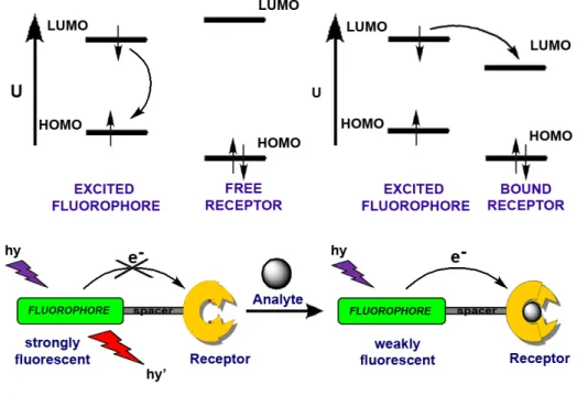
(37) 2.4.1. Photoinduced Electron Transfer (PET) Luminescent sensors provide an easy, sensitive, and often visual method for detection of a wide range of analytes such as cations, anions or neutral molecules. In certain cases, before relaxation occurs, excited molecule either can transfer an electron from some potential donor to fill its low-lying empty orbital or it may transfer an electron to another system which is usually called a quencher. In other words, the light absorbing molecule, termed as luminophore, after excitation may accept an electron into the vacancy in the ground state or it may donate an electron from its excited state. This process has been studied well due to its major role in photosynthesis 25 and since the electron is transferred after the absorption of light, the process is called photo-induced electron transfer (PET). If both of the components, luminophore and receptor where receptor is the other component that accepts/donates an electron from/to the luminophore, exist in the same molecule and linked by a nonconjugated bridge, then this molecular sensor can be called as the PET-type chemosensor.. Figure 10. PET mechanism. 21.
(38) Figure 10 illustrates the active and prohibited PET mechanisms in terms of frontier molecular orbitals. As it can be seen from the above figure, a model PET-type chemosensor is composed of three components which are luminophore, spacer and receptor units. Nature of the receptor unit determines the type of the response that luminophore will give upon analyte binding. In the above illustration the receptor unit is drawn as the electron donating component and in this particular case PET process is active via the electron transfer from HOMO of the receptor moiety to the semivacant ground state orbital of the luminophore which blocks the usual relaxation pathway of excited luminophore and quenches emission. This can also be termed as reductive photo-induced electron transfer. If the donor orbital on the receptor moiety that gives electron to the excited fluorophore can be controlled or somehow stabilized, to make PET thermodynamically less favored, an off-on type control over the fluorescence emission will be achieved. In other words, weakly luminescent sensor molecule will become strongly fluorescent when bonded to the targeted analyte. Accordingly, probes that exhibit this type of PET mechanism (reductive PET) are used widely in chemosensor designs. 26,27,28,29 Selectivity for analytes is achieved by the correct choice of recognition moiety for the desired ions and/or molecules. For this purpose, diverse range of molecular receptors has been synthesized by organic chemists. For example, in order to recognize the alkali metal cations, crown ethers are employed as useful receptors. Depending on the size of the crown ether it is going to bind to one of the cations selectively. Moreover, structural modifications on heteroatoms or some minor functionalizations within the crown structure could yield novel receptor molecules selective to different heavy metal cations. A very simple and classical example is compound 2 30 (Figure 11), which contains anthracene molecule as a fluorophore and an aza-crown receptor attached to it by the CH2 bridge. However, the recognition moiety is not necessary to be crown ether. There are also examples of cryptand- (3), 31 podand- (4), 32 dipicolylamine-, 33 and calixarene- 34 based PET sensors as selective for sodium, magnesium, potassium, calcium, and various transition metal ions. In these sensors photoinduced electron. 22.
(39) transfer quenches the luminescence in the absence of the analyte. Binding of the desired cation inhibits the PET and switches on the emission.. Figure 11. Some examples of PET based fluorescent chemosensors A molecule in the excited state, when compared to its corresponding ground state, not only is a better electron acceptor because of the created electron vacancy in the HOMO, it is also a better electron donor because of the promoted electron to a higher energy level. In the previous paragraphs, working principle of a PET type chemosensor that contains electron accepting fluorophore is briefly discussed. What if the receptor unit were to accept electron upon excitation? (Next page). Figure 12. Oxidative PET mechanism 23.
(40) This of course depends on the redox potentials of both the fluorophore and receptor units and the process in turn, can be referred to as the oxidative PET. Figure 12 illustrates the possible mechanism of the process in terms of the molecular orbitals involved. Contrary to the previous case, this time unbound form of the chemosensor exhibits strong luminescence, while the fluorescence of the bound species is quenched because of the active oxidative PET process. This is called an on-off system, since the emission intensity decreases significantly by the presence of an analyte. Compound 5 35 is a clear example exhibiting this mechanism. In that particular case depicted in figure 13, Bodipy dye was chosen as a fluorophore and 2,2-bipyridine for the receptor part. While the fluorophore has bright-green fluorescence in the absence of zinc cation, complexation with the mentioned ion quenches the fluorescence via oxidative PET mechanism.. Figure 13. Coordination of zinc triggers the oxidative PET mechanism Another study is a thiol sensor reported by Nagano, which again utilizes Bodipy derivative as the fluorophore and maleimide moiety as the receptor part (Figure 14). 36 This example displays very interesting results when compared with the previous example (Figure 13). Although the reported sensor here exhibits oxidative PET mechanism, in the paper they call it as donor-excited PET, the probe is strongly. 24.
(41) quenched before the maleimide part reacts with thiol. After the raction, the oxidative PET mechanism is blocked and the bright fluorescence of the Bodipy is restored back. Proposed schematic representation of the oxidative PET from excited Bodipy to maleimide in terms of molecular orbitals is also illustrated in figure 14. They have also synthesized meta- and para-maleimide bound structures to study the distance effect (between fluorophore and receptor) on the PET efficiency. More details are discussed briefly within the cited article.. Figure 14. Reverse PeT (d-PeT) mechanism In this section, principles of photo-induced electron transfer (PET) and its utilization in the development of molecular sensors have been discussed. Proposed mechanisms of PET process were illustrated schematically within the above figures. Literature examples for the PET type chemosensors were examined in terms of how blocking or activating this process will provide information on the nature of the analyte. No doubt that, among other conventional sensing mechanisms, PET, has been the most widely applied mechanism employed in the design of fluorescent chemosensors.. 25.
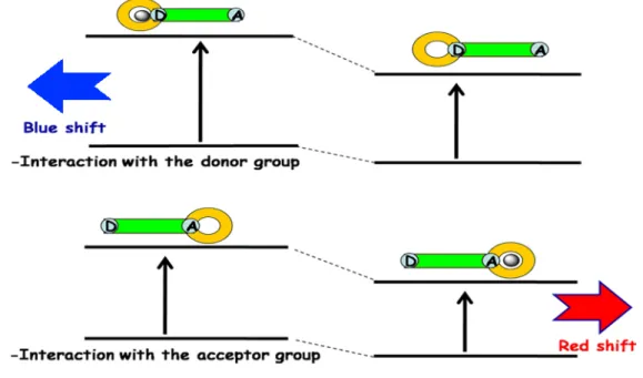
(42) 2.4.2. Intramolecular charge transfer (ICT) Intramolecular charge transfer is another type of signaling mechanism that generally lead to a red or blue shift in the emission spectrum of a fluorophore upon enhancement. and/or suppression. of this. process.. Contrary to. PET-type. chemosensors, there is no spacer unit between fluorophore and receptor units in ICTbased probes. The receptor unit is part the of π-electron system of the fluorophore such that one terminal is likely to be electron rich (electron donor) whereas the other one is electron poor (electron acceptor). When such a fluorophore-receptor system is excited with photons, a redistribution of electron density occurs and thus a dipole is created. This triggers an internal charge transfer (ICT) from donor to acceptor. Analyte binding leads to a positive or negative interaction with the excited state dipole, which results in significant changes in the both emission and absorption spectra. 37. Figure 15. Spectral displacements of PCT type sensors If the receptor unit contains an electron donating group (such as amino group) conjugated to the fluorophore, its interaction with a cation will decrease the electron donating capability of that group. In other words, this type of interaction leads to a. 26.
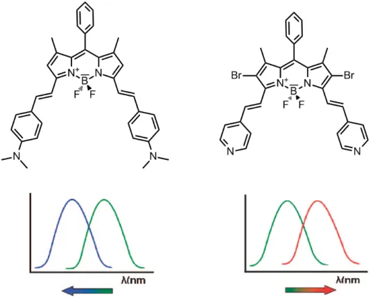
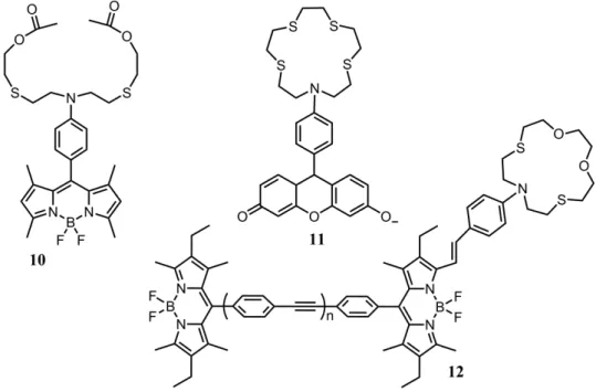
(43) reduction of conjugation and a blue shift is monitored in the absorption spectrum. However, if the cation is in close interaction with the acceptor group (such as carbonyl group), this improves the electron withdrawing character of that group, resulting in the stabilization of the system and red shift in the absorption spectrum. 38 Photophysical changes occurring upon cation binding can also be explained by charge dipole interactions. 39 The electron donating group will be positively charged in the excited state and its interaction with the cation will destabilize the excited state more than the ground state. Hence, this increase in the energy gap between ground and excited states will cause a blue shift in the both absorption and emission spectra. Conversely, if the receptor unit contains an electron accepting group (such as carbonyl group) conjugated to the fluorophore, its interaction with a cation will stabilize the excited state more than the ground state. As a result, the energy gap between the ground state and the excited state will decrease and red-shift will be monitored in the both absorption and emission spectra (Figure 15). Many fluoroionophores have been designed according to this (ICT) mechanism so far. Compounds 6 40 and 7 41 (Figure 16) exhibit blue shift in both absorption and emission spectra upon cation binding.. Figure 16. Crown containing PCT sensors Depending on the receptor moiety, similar compounds can display different spectral shifts upon the binding of the same analyte. For example, two bodipy dyes showing similar spectral properties (Figure 17) exhibit opposite spectral shifts upon protonation. 42 One of the dyes includes electron donating aniline moiety whereas the other contains electron accepting pyridine unit as receptor parts. Consequently, those. 27.
(44) two compounds demonstrate spectral shifts in the opposite directions in their proton bound form, due to the reasons explained above.. Figure 17. Bidirectional switching of the dyes related to ICT donor and acceptor characteristics. Conjugated compounds containing both electron donor (D) and electron withdrawing (A) groups that exhibit intramolecular charge transfer (ICT) through the πconjugated bridge are also termed as the 'Push-Pull' systems (D-π-A systems). Apart from the chemosensing and analyte monitoring applications described above, this kind of systems has also found wide range of optical-electrical applications, such as organic light emitting devices, 43,44 nonlinear optical devices, 45 and solar cell materials. 46,47. 28.
(45) 2.4.3. Energy Transfer (ET) Energy transfer is another signaling event, which can be classified as electronic energy transfer (EET) and/or fluorescence resonance energy transfer (FRET) depending on the interaction distance between energy donor and energy acceptor units within a multichromophoric dye systems. It is the process where the energy of donor chromophore (D), which absorbs light at relatively short wavelength,. is. transferred to acceptor dye (A) that fluoresces at longer wavelength (as long as it is not a 'quencher' type dye molecule). In other words, energy of the donor (D) at its excited state is used to excite the acceptor through energy transfer.. Figure 18. Förster type (through space) and Dexter type (through bond) ET As it is stated above, it is the interaction distance between donor and acceptor units that determine the type of energy transfer mechanism occurring efficiently. EET, which is also called as Dexter electron transfer, is taking place if the distance mentioned above remains within 10Ǻ range. On the other hand, for an efficient FRET to occur the distance between donor and acceptor should be from 10 to 100 Ǻ. However, this is not the only requirement for efficient FRET, there should be a certain degree of overlap between the emission spectrum of donor and the absorption spectrum of acceptor moieties (Figure 18).. 29.
(46) These two types of energy transfer mechanisms, also known as Dexter and Förster type, will be covered briefly in the following subsections. Energy transfer characterizations can be done following various parameters such as relative lifetimes, quantum yields, and decrease in the donor emission and increase in the acceptor emission intensities. It is also influenced from the rate of deactivation pathways from the excited system and therefore, chromophores must be appropriate to compete with those pathways. 48 Besides, excited state lifetime of donor has to be longer than the time required for energy transfer.. 2.4.3.1. Förster type Energy Transfer Fluorescent labels that emit light at wavelengths distant from that of the source used to excite them have many applications in biotechnology. Generally, a simple florescent organic dye molecule has a very small Stokes’ shift. When the Stokes` shift of a single dye is insufficient for a particular application, bi(multi)chromophoric systems that exploit through-space energy transfer between two dyes are frequently used. Fluorescence resonance energy transfer (FRET) occuring here is also called Förster type Energy Transfer, and is a nonradiative process whereby an excited state donor (D) transfers energy to a spatially close ground state acceptor (A), and the fluorescence of the latter is observed (Figure 19).. Figure 19. Schematic representation of the FRET process. 30.
(47) In other words, an electron in HOMO of the acceptor is excited to its LUMO through the energy released during the relaxation of an electron in the LUMO of the donor to its HOMO. The energy absorbed by the acceptor unit matches the emission wavelength of the donor (spectral overlap). As donor and acceptor moieties are usually connected via non-conjugated linker, FRET does not depend on the orbital interaction between these units (D an A). Thus, a large distance between donor and acceptor groups (10-100 Ǻ) would still allow this type of energy transfer to occur. Spectral overlap between donor emission and acceptor absorption, the distance between donor and acceptor and relative orientations of their transition dipoles are significantly important parameters for an efficient FRET process. 49,50 FRET efficiency can be determined using two different approaches; one is steady state approach and the other is time-resolved approach.19 Decrease in quantum yield of donor is followed in the former case. In this method, self absorption, which refers to re-absorption of the emitted light by the same molecule, is an important problem that should be avoided. This problem might be solved by the use of very dilute solutions.51 FRET efficiency with steady state approach can be formulated as follows: E = 1 – (Φ DA / ΦD) where Φ DA and ΦD are the quantum yields of donor molecule in the presence and the absence of acceptor, respectively. It can also be calculated with a different formula, which is based on the increase in the fluorescence of acceptor: E = AA (λD) / AD (λD) * [IAD(λAem) / IA(λA em) - 1] where AA and AD refer to absorbance values of acceptor and donor at the maximum absorbance wavelength of donor. IAD and IA refer to integrated emission area of acceptor in the presence and absence of donor at λAem respectively.. 31.
(48) Time resolved approach enables a more accurate FRET efficiency calculation, which is determined using time-resolved emission data of donor and acceptor units. When the decay of emission is a single exponential, FRET efficiency can be formulated as follows:19 E = τD*kFRET / (1 + τD*kFRET) kFRET = 1/τDA - 1/τD where τD and τDA refer to excited state decay time (lifetime) of donor in the absence and presence of acceptor, respectively. A very common example exhibiting Förster type energy transfer process is shown below (Figure 20). In this article Bodipy dyes were selected as the energy donor molecules, whereas perylene diimide as the acceptor unit. Four Bodipy molecules are covalently attached to a perylene core via 'click' reaction. The extinction coefficient of the final molecule at Bodipy’s maximum absorption wavelength (526 nm) dramatically increases up to 250000 M-1cm-1 due to four Bodipy units in the structure. The emission of the core has enhanced, as expected, with the increasing number of terminal Bodipy donors. FRET efficiency is calculated as 99% with a critical Förster radius of 4.7 nm. 52. Figure 20. A Bodipy based Förster type energy transfer system 32.
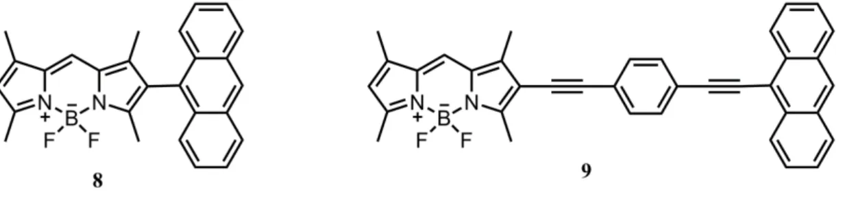
(49) Within the past three decades, the use of Förster energy transfer has found applications in highly diverse fields, including light frequency conversion, cascade systems, artificial photosynthetic antenna, singlet oxygen generation and switching element in molecular machines.. 2.4.3.2. Dexter type Energy Transfer On the contrary to the Förster type, Dexter type energy transfer requires donoracceptor orbital interaction which can be provided either directly or by the bridge. 53 It usually happens in the systems where donor and acceptor units are connected by a conjugated linker. That's why it is also called as 'through-bond' energy transfer. In this kind of energy transfer, an exchange of electrons occurs between both HOMOs and LUMOs of donor and acceptor (Figure 18). As it is highly dependent on the orbital overlap, which requires a short-range interaction (<10 Ǻ), the rate constant of energy transfer decreases exponentially with distance: 54 kET = K J exp(-2RDA / L) where K represents orbital interaction, J is the overlap integral between donor emission and acceptor absorbance, RDA is the donor acceptor separation and L is the Van der Waals radii.. Figure 21. Through-bond energy transfer cassettes Burgess et al synthesized a series of Anthracene-Bodipy cassettes in order to measure the rates of energy transfer when the orientation of donor and acceptor moieties are changed (Figure 21). 55. 33.
Şekil


+7

Benzer Belgeler
骨粉產品介紹 (以下資料由廠商提供、編輯部整理;詳細資料請洽各廠商) 產 品 外 觀 博納骨 人工骨 替代物 「和康」富瑞密骨骼 填補顆粒
[r]
Bu çalışmada, yaş ve kuru tip yaşa bağlı makula dejenerasyonu (YBMD) hastalarında arteriyel sertliği kalp ayak bileği vaskuler indeks (cardio - ankle vascular
Laparoskopik cerrahiyi uzman olduktan sonra kursiyer olarak öğrenen ve kliniğinde laparoskopi deneyimi olmayan bir ürolog basit ve orta zorlukta sayılan operasyonları yaptıktan
With the aim of understanding why we are observing the appearance and the disappearance of metallic states in the spectrum by varying the radial confinement (and thus the effective
What motivates our work is the need for a convenient and flexible natural language-based interface to complement the text-based query interface and the visual query interface of
For this question science and technology teachers often had the misconception that while moon rotates around the earth meanwhile the earth revolves in its orbit and as a result
In a trial conducted by Metcalfe (16) et al., rate of ath- erosclerotic renal artery disease in patients with PAD in ≥ 3 segments (43,4%) was found to be higher than in patients
